2022 TOYOTA GR SUPRA ESP
[x] Cancel search: ESPPage 111 of 356

1113-1. CONTROLS
3
CONTROLS
After using a child restraint sys-
tem on the front passenger seat,
ensure that the front, knee, and
side airbags on the front pas-
senger side are deactivated. For
automatic deactivation of front-
seat passenger airbags, refer to
page 170.
The right place for chil-
dren
Safety information
WARNING
Unattended children or animals in
the vehicle can cause the vehicle
to move and endanger them-
selves and traffic, for instance due
to the following actions:
●Pressing the Start/Stop button.
●Releasing the parking brake.
●Opening and closing the doors
or windows.
●Engaging selector lever position
N.
●Using vehicle equipment.
There is a risk of accidents or inju-
ries. Do not leave children or ani-
mals unattended in the vehicle.
Take the remote control with you
when exiting and lock the vehicle.
WARNING
A heated vehicle may result in
death to persons, especially chil-
dren and animals. There is a risk
of injuries or danger to life. Do not
leave persons, especially chil-
dren and animals unattended in
the vehicle.
WARNING
Exposure to intense sunlight can
cause child restraint systems and
their components to become very
hot. Persons may sustain burn
injuries when touching the hot
components. There is a risk of
injury. Do not expose the child
restraint system to direct sunlight
or cover where necessary. If nec-
essary, let the child restraint sys-
tem cool down before transporting
a child. Do not leave children
unattended in the vehicle.
Children on the front pas-
senger seat
General information
Safety information
WARNING
Active front-seat passenger air-
bags can injure a child in a child
restraint system when the airbags
are activated. There is a risk of
injury. Make sure that the
front-seat passenger airbags are
deactivated and that the PAS-
SENGER AIRBAG OFF indicator
light lights up.
Page 114 of 356

1143-1. CONTROLS
1Unbuckle the safety belt
buckle.
2 Remove the child restraint
system.
3 Allow the belt strap to be
pulled in completely.
1Direction of travel
2 Head restraint
3 Hook for the upper retaining
strap
4 Mounting point/eyelet
5 Vehicle floor
6 Seat
7 Upper retaining strap
1 Open the anchor cover.
Unlocking the safety belt
Child restraint systems
with tether strap
Safety information
WARNING
If the upper retaining strap is
incorrectly used for the child
restraint system,
the protective
effect can be reduced. There is a
risk of injury. Make sure that the
upper retaining strap is not guided
across sharp edges and without
twisting to the upper retaining
strap.
WARNING
The attachment points for child
restraint systems in the vehicle
are intended for attaching child
restraint systems only. When
other objects are mounted, the
anchors can be damaged. There
is a risk of injury or risk of damage
to property. Attach only child
restraint systems at the corre-
sponding attachment points.
Anchors
SymbolMeaning
The respective sym-
bol shows the anchor
for the upper retaining
strap. Seats with an
upper top tether are
marked with this sym-
bol. It can be found on
the rear seat backrest
or the rear window
shelf.
Routing the retaining strap
Attaching the upper retain-
ing strap to the anchor
Page 128 of 356

1283-1. CONTROLS
In some situations, the vehicle is
to roll without its own power for
a short distance, for instance in
a vehicle wash, or be pushed.
1Switch on drive-ready state
while pressing on the brake
pedal.
2 If necessary, release the
parking brake.
3 Depress the brake pedal.
4 Touch the selector lever lock
and engage selector lever
position N.
5 Switch off drive-ready state.
In this way, standby state remains
switched on, and a vehicle mes-
sage is displayed.
The vehicle can roll.
Irrespective of standby state, the
selector lever position P is auto-
matically engaged after approx.
35 minutes.
If there is a malfunction, you may not be able to change the
selector lever position.
Electronically unlock the trans-
mission lock, if needed, refer to
page 130.
Kickdown is used to achieve
maximum driving performance.
Step on the accelerator pedal
beyond the resistance point at
the full throttle position.
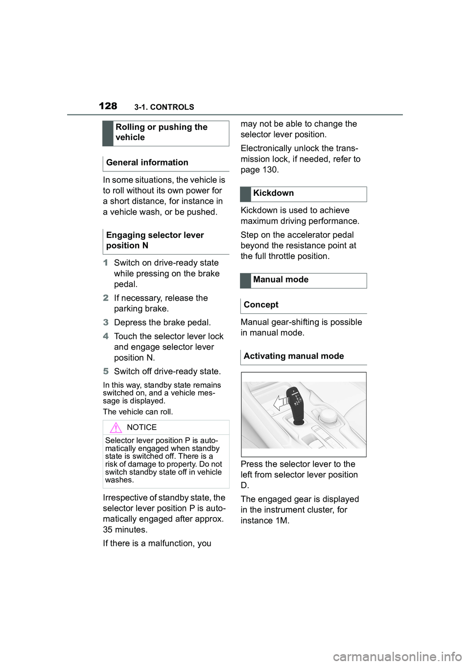
Manual gear-shifting is possible
in manual mode.
Press the selector lever to the
left from selector lever position
D.
The engaged gear is displayed
in the instrument cluster, for
instance 1M.
Rolling or pushing the
vehicle
General information
Engaging selector lever
position N
NOTICE
Selector lever pos ition P is auto-
matically engaged when standby
state is switched off. There is a
risk of damage to property. Do not
switch standby state off in vehicle
washes.
Kickdown
Manual mode
Concept
Activating manual mode
Page 145 of 356

1453-1. CONTROLS
3
CONTROLS
When passing buses or trucks
with traffic signs applied to
them.
If the traffic signs are
non-conforming.
When signs that are valid for
a parallel road are detected.
In the presence of coun-
try-specific signs and road
configurations.
The display can be operated
when necessary.
Entertainment source.
Current audio source.
List of most recent telephone
calls.
If necessary, the corresponding
menu will open on the Control
Display.
Items displayed may differ
depending on the specifications
of the vehicle.
The lists can be displayed and
operated using the buttons on
the steering wheel. The Onboard Computer dis-
plays different vehicle data in
the instrument cluster, such as
average values.
Selection lists
Concept
Display
Displaying and using the
list
ButtonFunction
Change the entertain-
ment source.
Pressing the button
again will close the cur-
rently displayed list.
Show list of most
recent telephone calls.
Turn the thumbwheel:
select entertainment
source or list entry.
Press the thumbwheel
to confirm the setting.
The currently selected
list can be displayed
again in the instrument
cluster by turning the
thumbwheel.
Onboard Computer in the
instrument cluster
Concept
Calling up information
Page 156 of 356

1563-1. CONTROLS
4"Daytime running lamps"
The Automatic high-beam
detects other traffic participants
early on and automatically
switches the high beams on or
off depending on the traffic situ-
ation.
The Automatic high-beam
ensures that the high beams are
switched on, whenever the traf-
fic situation allows. In the low
speed range, the high beams
are not switched on by the sys-
tem.
The system responds to light
from oncoming traffic and traffic
driving ahead of you, and to
ambient lighting, for instance in
towns and cities.
The high beams can be
switched on and off manually at
any time.
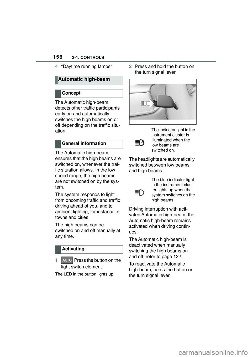
1 Press the button on the
light switch element.
The LED in the button lights up.
2 Press and hold the button on
the turn signal lever.
The headlights are automatically
switched between low beams
and high beams.
Driving interruption with acti-
vated Automatic high-beam: the
Automatic high-beam remains
activated when driving contin-
ues.
The Automatic high-beam is
deactivated when manually
switching the high beams on
and off, refer to page 122.
To reactivate the Automatic
high-beam, press the button on
the turn signal lever.
Automatic high-beam
Concept
General information
Activating
The indicator light in the
instrument cluster is
illuminated when the
low beams are
switched on.
The blue indicator light
in the instrument clus-
ter lights up when the
system switches on the
high beams.
Page 157 of 356

1573-1. CONTROLS
3
CONTROLS
Press and hold the button on the
turn signal lever.
The sensitivity of the Automatic
High Beam Assistant can be
adjusted.
• Setting at standstill only.
• Drive readiness is switched on.
• Light is turned off. Push the turn signal lever to the
front for approximately 10 sec-
onds.
A Check Control message is
displayed. The system responds
more sensitively.
Push the turn signal lever to the
front again for approx. 10 sec-
onds or switch off the
drive-ready state.
The sensitivity of the Automatic
High Beam Assistant is reset to the
factory settings.
The Automatic High Beam
Assistant cannot replace the
driver's personal judgment of
when to use the high beams. In
situation that require this, there-
fore dimming manually.
The system is not fully functional
in the following situations, and
driver intervention may be nec-
essary:
In very unfavorable weather
conditions, such as fog or
heavy precipitation.
When detecting poorly-lit road
users such as pedestrians,
cyclists, horseback riders and
wagons; when driving close to
train or ship traffic; or at ani-
Deactivate Automatic High
Beam Assistant
Sensitivity of the Auto-
matic High Beam Assis-
tant
General information
WARNING
If adjustments have been made or
the sensitivity has been modified,
oncoming traffic may be momen-
tarily blinded. There is a risk of an
accident. If adjustments have
been made and the sensitivity has
been modified, make sure that
oncoming traffic is not momentar-
ily blinded. Switch off the high
beams manually if required.
Functional requirements
Increase sensitivity
Resetting the sensitivity
System limits
Page 160 of 356

1603-1. CONTROLS
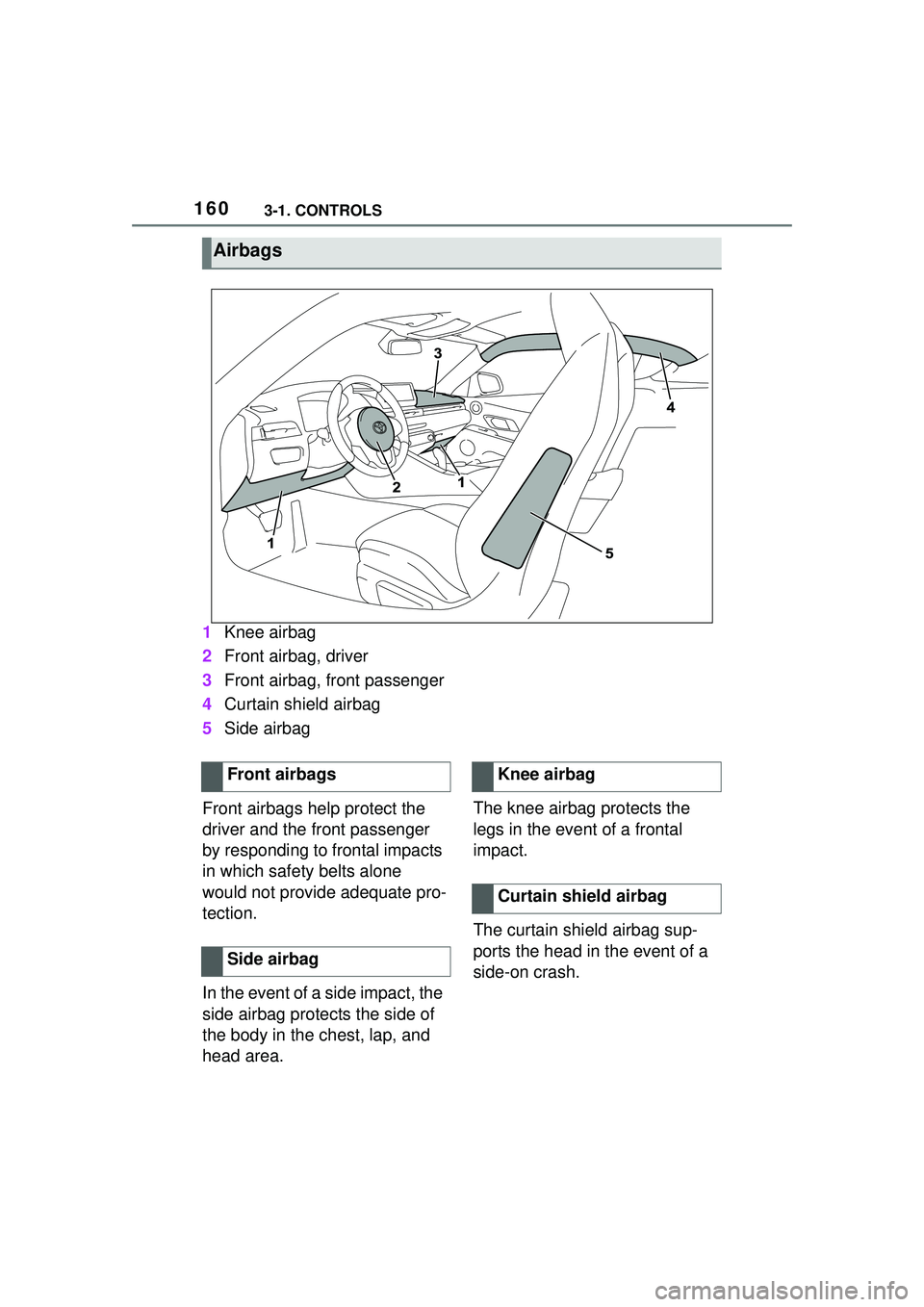
1Knee airbag
2 Front airbag, driver
3 Front airbag, front passenger
4 Curtain shield airbag
5 Side airbag
Front airbags help protect the
driver and the front passenger
by responding to frontal impacts
in which safety belts alone
would not provide adequate pro-
tection.
In the event of a side impact, the
side airbag protects the side of
the body in the chest, lap, and
head area. The knee airbag protects the
legs in the event of a frontal
impact.
The curtain shield airbag sup-
ports the head in the event of a
side-on crash.
Airbags
Front airbags
Side airbagKnee airbag
Curtain shield airbag
Page 162 of 356

1623-1. CONTROLS
Do not hang pieces of cloth-
ing, such as jackets, over the
backrests.
Never modify either the indi-
vidual components or the wir-
ing in the airbag system. This
also applies to steering wheel
covers, the dashboard, and
the seats.
Do not remove the airbag sys-
tem.
Even when you follow all
instructions very closely, injury
from contact with the airbags
cannot be fully ruled out in cer-
tain situations.
The ignition and inflation noise
may lead to short-term and, in
most cases, temporary hearing
impairment in sensitive occu-
pants.
Vehicle modifications for a per-
son with disabilities may affect
the air bag system; contact the
Toyota dealer for further infor-
mation.
Warnings and information on the
airbags are also found on the
sun visors. Functional readiness of
the airbag system
Safety information
WARNING
Individual components can be hot
after triggering of the airbag sys-
tem. There is a risk of injury. Do
not touch individual components.
WARNING
Improperly executed work can
lead to failure, malfunction or
unintentional triggering of the air-
bag system. In the case of a mal-
function, the airbag system might
not trigger as intended despite the
accident severity. There is a risk
of injuries or danger to life. Have
the airbag system checked,
repaired, dismantled and
scrapped by your Toyota dealer.
Display in the instrument
cluster
When drive-ready state is
switched on, the warning
light in the instrument
cluster lights up briefly and
thereby indicates the func-
tion readiness of the entire
airbag system and the belt
tensioners.
Malfunction
Warning light does not
come on when
drive-ready state is
switched on.
The warning light lights
up continuously.