2022 TOYOTA GR SUPRA ESP
[x] Cancel search: ESPPage 190 of 356

1903-1. CONTROLS
area or after deactivation of the
turn signal.
A flashing of the light during
vehicle unlocking serves as sys-
tem self-test.
If the vehicle speed exceeds
approx. 155 mph/250 km/h, the
system is deactivated temporar-
ily.
If the vehicle speed falls below
approx. 155 mph/250 km/h, the
system once again responds
according to the setting.
Additional information:
• Radar sensors, refer to page 40. The system may not be fully
functional in the following situa-
tions:
When a vehicle is approach-
ing at a speed much faster
than your own.
In heavy fog, wet conditions,
or snowfall.
In tight curves or on narrow
lanes.
If the bumper is dirty, iced up,
or covered, for instance by
stickers.
After improperly performed
work on the vehicle paint.
If cargo protrudes.
A vehicle message is displayed
when the system is not fully
functional.
Depending on the selected
warning settings, e.g., warning
time, more or fewer warnings
can be displayed. However,
there may also be an excess of
premature warnings of critical
situations.
Depending on the equipment
Flashing of the light
System limits
Safety information
WARNING
The system is designed to oper-
ate in certain conditions and cir-
cumstances. Due to conditions or
other factors, the system may not
respond. There may be a risk of
accident or risk of damage to
property. Actively intervene as
needed. Refer to the information
in this Owner’s Manual regarding
the scope of the system’s opera-
tion and limitations.
Upper speed limit
System limits of the sensors
Functional limitations
Displaying warnings
Rear-end collision prepa-
ration
Principle
Page 195 of 356

1953-1. CONTROLS
3
CONTROLS
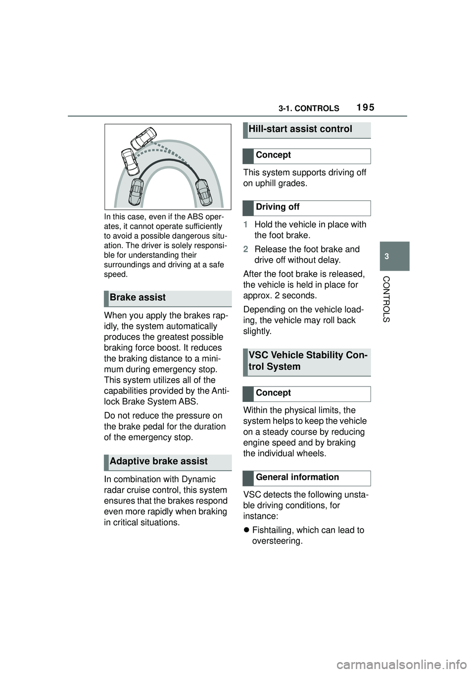
In this case, even if the ABS oper-
ates, it cannot operate sufficiently
to avoid a possible dangerous situ-
ation. The driver is solely responsi-
ble for understanding their
surroundings and driving at a safe
speed.
When you apply the brakes rap-
idly, the system automatically
produces the greatest possible
braking force boost. It reduces
the braking distance to a mini-
mum during emergency stop.
This system utilizes all of the
capabilities provided by the Anti-
lock Brake System ABS.
Do not reduce the pressure on
the brake pedal for the duration
of the emergency stop.
In combination with Dynamic
radar cruise control, this system
ensures that the brakes respond
even more rapidly when braking
in critical situations.This system supports driving off
on uphill grades.
1
Hold the vehicle in place with
the foot brake.
2 Release the foot brake and
drive off without delay.
After the foot brake is released,
the vehicle is held in place for
approx. 2 seconds.
Depending on the vehicle load-
ing, the vehicle may roll back
slightly.
Within the physical limits, the
system helps to keep the vehicle
on a steady course by reducing
engine speed and by braking
the individual wheels.
VSC detects the following unsta-
ble driving conditions, for
instance:
Fishtailing, which can lead to
oversteering.
Brake assist
Adaptive brake assist
Hill-start assist control
Concept
Driving off
VSC Vehicle Stability Con-
trol System
Concept
General information
Page 197 of 356

1973-1. CONTROLS
3
CONTROLSWhen entering a curve at an
excessively high rate of speed
In this case, even if the VSC oper-
ates, it cannot operate sufficiently
to avoid a possible dangerous situ-
ation. The driver is solely responsi-
ble for understanding their
surroundings and driving at a safe
speed.
Traction mode is a version of the
VSC Vehicle Stability Control
System where forward momen-
tum is optimized. The system ensures maximum
headway on special road condi-
tions or loose road surfaces, for
instance unplowed snowy
roads, but with somewhat lim-
ited driving stability.
When Traction mode is acti-
vated, the vehicle has maximum
traction. Driving stability is lim-
ited during acceleration and
when driving in curves.
You may find it useful to briefly
activate Traction mode in the
following situations:
When driving in slush or on
uncleared, snow-covered
roads.
When driving off from deep
snow or loose ground.
When driving with snow
chains.
Indicator/warning lights
The indicator light lights
up: VSC is deactivated.
The indicator light flashes:
VSC controls the drive
and braking forces.
The indicator light lights
up: VSC has malfunc-
tioned.
Situations which the VSC
cannot operate sufficiently
Traction mode
Concept
General information
Overview
Button in the vehicle
VSC OFF
Page 198 of 356

1983-1. CONTROLS
If Traction mode is activated,
TRACTION is displayed in the
instrument cluster.
In certain situations, the VSC is
activated automatically:
If Dynamic radar cruise con-
trol with full-speed range is
activated.
On a braking intervention by
the Toyota Supra Safety sys-
tems.
The vehicle has a flat tire.
*: if equipped
The active differential step-
lessly locks the rear axle
depending on the driving condi-
tions. This provides optimal
power transfer in all driving con-
ditions by helping prevent wheel
spin at either rear wheel.
The driver is responsible adapt-
ing his or her driving style to the
situation.
Activating/deactivating
Traction mode
Activating Traction mode
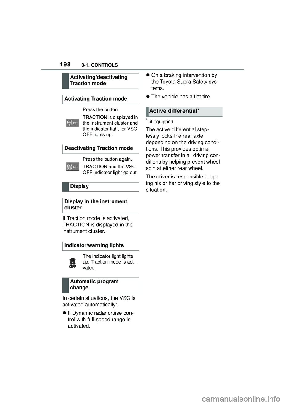
Press the button.
TRACTION is displayed in
the instrument cluster and
the indicator light for VSC
OFF lights up.
Deactivating Traction mode
Press the button again.
TRACTION and the VSC
OFF indicator light go out.
Display
Display in the instrument
cluster
Indicator/warning lights
The indicator light lights
up: Traction mode is acti-
vated.
Automatic program
change
Active differential*
Page 203 of 356

2033-1. CONTROLS
3
CONTROLS
*: if equipped
Using this system, a desired
speed and a distance to a vehi-
cle ahead can be adjusted using
the buttons on the steering
wheel.
The system maintains the
desired speed on clear roads.
For this purpose, the vehicle
accelerates or brakes automati-
cally.
If a vehicle is driving ahead of
you, the system adjusts the
speed of your vehicle so that the
set distance to the vehicle
ahead is maintained. The speed
is adjusted as far as the given
situation allows.
Depending on the vehicle set-
tings, the characteristics of the
Cruise Control may change.
The distance can be adjusted in
several steps. For safety rea-
sons, it depends on the respec-
tive speed.
If the vehicle ahead of you
brakes to a halt, and then pro-
ceeds to drive again within a
brief period, the system is able to detect this within the given
system limits.
Dynamic radar cruise
control with full-speed
range*
Concept
General information
Safety information
WARNING
The system cannot serve as a
substitute for the driver’s personal
judgment in assessing the traffic
conditions. Based on the limits of
the system, it cannot inde-
pendently react to all traffic situa-
tions. There is a risk of accident.
Adjust driving style to traffic condi-
tions. Watch traffic closely and
actively intervene where apaprk-
ing sensorspropriate.
WARNING
An unsecured vehicle can begin
to move and possibly roll away.
There is a risk of an accident.
Before exiting, secure the vehicle
against rolling.
In order to ensure that the vehicle
is secured against rolling away,
follow the following:
●Set the parking brake.
●On uphill grades or on a down-
hill slope, turn the front wheels
in the direction of the curb.
●On uphill grades or on a down-
hill slope, also secure the vehi-
cle, for instance with a wheel
chock.
WARNING
The desired speed can be incor-
rectly adjusted or called up by
mistake. There is a risk of an acci-
dent. Adjust the desired speed to
the traffic conditions. Watch traf-
fic closely and actively intervene
where appropriate.
Page 211 of 356

2113-1. CONTROLS
3
CONTROLS
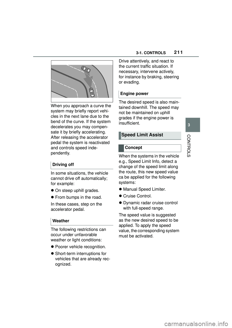
When you approach a curve the
system may briefly report vehi-
cles in the next lane due to the
bend of the curve. If the system
decelerates you may compen-
sate it by briefly accelerating.
After releasing the accelerator
pedal the system is reactivated
and controls speed inde-
pendently.
In some situations, the vehicle
cannot drive off automatically;
for example:
On steep uphill grades.
From bumps in the road.
In these cases, step on the
accelerator pedal.
The following restrictions can
occur under unfavorable
weather or light conditions:
Poorer vehicle recognition.
Short-term interruptions for
vehicles that are already rec-
ognized. Drive attentively, and react to
the current traffic situation. If
necessary, intervene actively,
for instance by braking, steering
or evading.
The desired speed is also main-
tained downhill. The speed may
not be maintained on uphill
grades if the engine power is
insufficient.
When the systems in the vehicle
e.g., Speed Limit Info, detect a
change of the speed limit along
the route, this new speed value
ca be applied for the following
systems:
Manual Speed Limiter.
Cruise Control.
Dynamic radar cruise control
with full-speed range.
The speed value is suggested
as the new desired speed to be
applied. To apply the speed
value, the corresponding system
must be activated.
Driving off
Weather
Engine power
Speed Limit Assist
Concept
Page 217 of 356

2173-1. CONTROLS
3
CONTROLS
Via Toyota Supra Command:
1"My vehicle"
2 "Vehicle settings"
3 "Parking"
4 "Park. Sens. w. em. braking
funct."
5 "Park. Sens. w. em. braking
funct."
The system warns of obstacles
on the side of the vehicle.
The system uses the ultrasound
sensors of Parking Sensor and
parking assistant.
To protect the sides of the vehi-
cle, obstacle markings are dis- played on the sides of the
vehicle.
Color markings: warning
against detected obstacles.
Gray markings, hatched area:
no obstacles were detected.
No markings, black area: the
area next to the vehicle was
not yet captured.
The system only displays sta-
tionary obstacles that were pre-
viously detected by sensors
while passing them.
The system does not detect
whether an obstacle moves later
on. If the vehicle is stationary,
the markings are shown in black
after a certain time. The area
next to the vehicle must be
newly captured.
Activating/deactivating the
system
Depending on the equip-
ment version: side parking
aid
Concept
General information
Display
Limits of side parking aid
System limits
Safety information
WARNING
The system is designed to oper-
ate in certain conditions and cir-
cumstances. Due to conditions or
other factors, the system may not
respond. There may be a risk of
accident or risk of damage to
property. Actively intervene as
needed. Refer to the information
in this Owner’s Manual regarding
the scope of the system’s opera-
tion and limitations.
Page 220 of 356

2203-1. CONTROLS
More than one assistance func-
tion can be active at the same
time.
The assistance functions can be
manually activated.
1Move the Controller to the
right, if needed.
2 With corresponding equip-
ment:
3 With corresponding equip-
ment: "Camera image"
"Parking aid lines".
Pathway lines and turning radius
lines are displayed, refer to page
220.
"Obstacle marking".
Depending on the vehicle equip-
ment, the obstacles detected by
Parking Sensors are displayed,
refer to page
221, by markings.
■Pathway lines Pathway lines help you to esti-
mate the space required when
parking and maneuvering on
level roads.
Pathway lines depend on the
steering angle and are continu-
ously adjusted to the steering
wheel movements.
■Turning radius lines
Turning radius lines can only be
superimposed on the camera
image together with pathway
lines.
Turning radius lines show the
course of the smallest possible
turning radius on a level road.
Only one turning radius line is
displayed after the steering
wheel is turned past a certain
angle.
■Parking using pathway and
turning radius lines
1 Position the vehicle so that
the red turning radius line
leads to within the limits of
the parking space.
2 Turn the steering wheel to
the point where the green
pathway line covers the cor-
Display on the Control Dis-
play
General information
Parking aid lines