2022 TOYOTA GR SUPRA battery
[x] Cancel search: batteryPage 240 of 356

2403-1. CONTROLS
devices.
Charging current:
max. 1.5 A (vehicles without wire-
less charger)
max. 2.1 A (vehicles with wireless
charger)
For data transfer.
The wireless charging tray
enables the following functions
to be performed without cables:
Charging the rechargeable
battery of a mobile phone with
Qi capability and of other
mobile devices, which support
the Qi standard.
Connect the mobile phone to
the external antenna.
Depending on the country, this pro-
vides for better network reception
and a consistent reproduction qual-
ity.
When inserting the mobile
phone, make sure there are no
objects between it and the wire-
less charging tray.
During charging, the surface of
the tray and the mobile phone
may become warm. Higher tem-
peratures may lead to a reduc-
tion in the charge current through the mobile phone, and
in isolated cases the charging
process is paused temporarily.
Follow the relevant instructions
in the mobile phone owner's
manual.
If the vehicle is equipped
with a charge indicator, the Con-
trol Display shows whether a
mobile phone with Qi capability
is being charged.
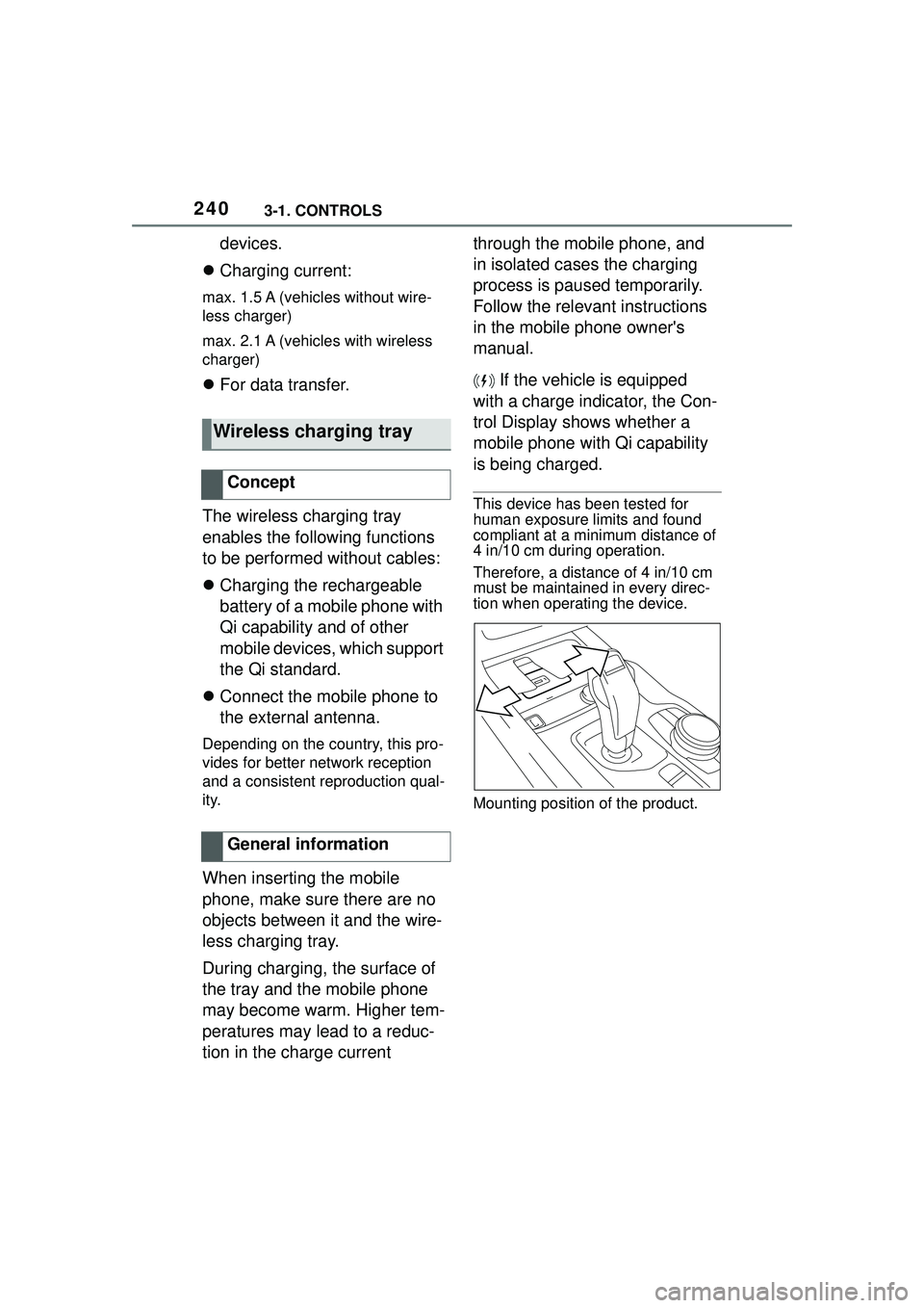
This device has been tested for
human exposure limits and found
compliant at a minimum distance of
4 in/10 cm during operation.
Therefore, a distance of 4 in/10 cm
must be maintained in every direc-
tion when operating the device.
Mounting position of the product.
Wireless charging tray
Concept
General information
Page 291 of 356

2915-1. MOBILITY
5
MOBILITY
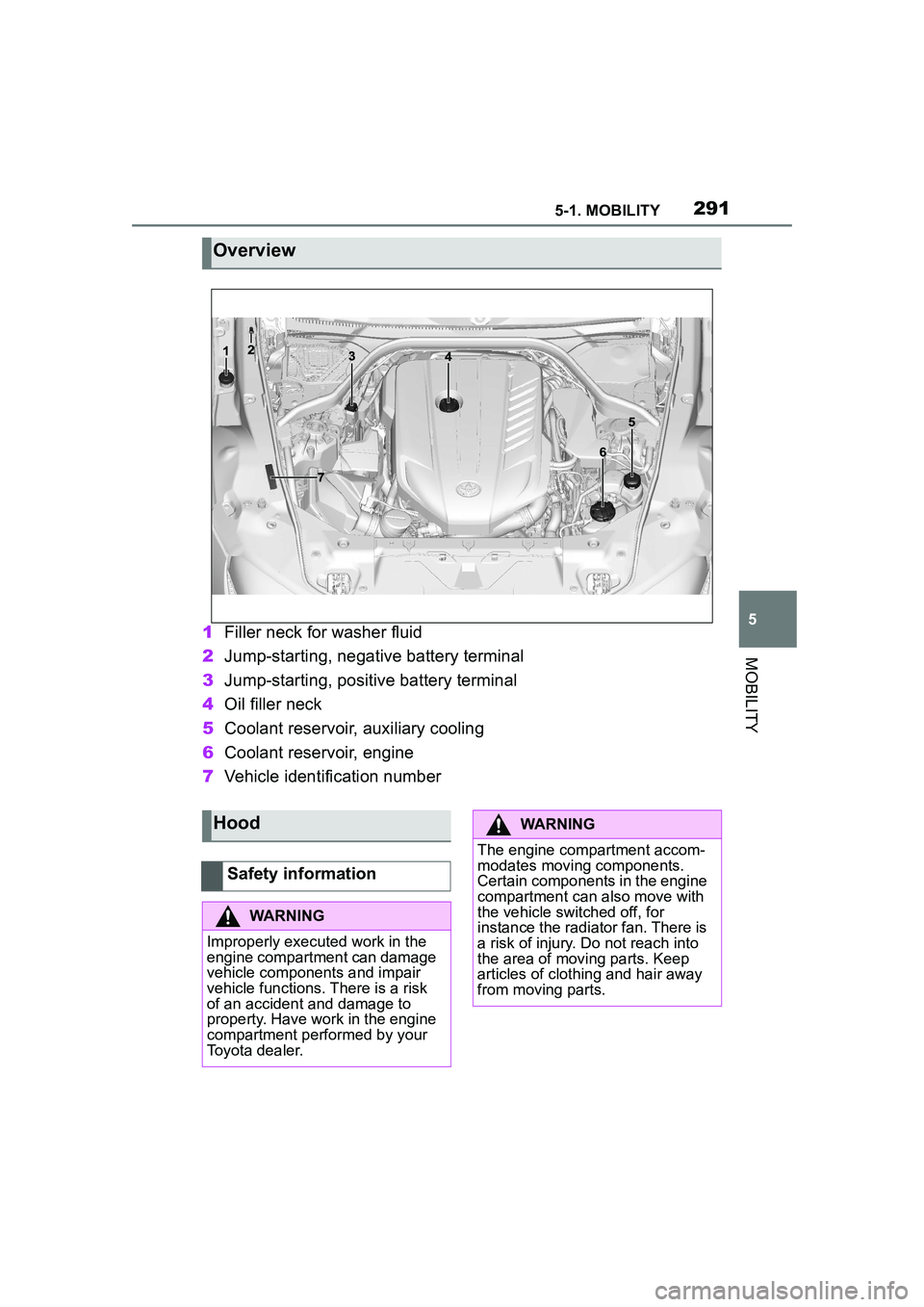
1Filler neck for washer fluid
2 Jump-starting, negative battery terminal
3 Jump-starting, positive battery terminal
4 Oil filler neck
5 Coolant reservoir, auxiliary cooling
6 Coolant reservoir, engine
7 Vehicle identification number
Overview
Hood
Safety information
WARNING
Improperly executed work in the
engine compartment can damage
vehicle components and impair
vehicle functions. There is a risk
of an accident and damage to
property. Have work in the engine
compartment performed by your
Toyota dealer.
WARNING
The engine compartment accom-
modates moving components.
Certain components in the engine
compartment can also move with
the vehicle switched off, for
instance the radiator fan. There is
a risk of injury. Do not reach into
the area of moving parts. Keep
articles of clothing and hair away
from moving parts.
Page 301 of 356

3015-1. MOBILITY
5
MOBILITY
This chapter describes all stan-
dard, country-specific and
optional features offered with
the series. It also describes fea-
tures and functions that are not
necessarily available in your
vehicle, e.g., due to the selected
options or country versions. This
also applies to safety-related
functions and systems. When
using these functions and sys-
tems, the applicable laws and
regulations must be observed.
The maintenance system pro-
vides service notifications and
thereby provides support in
maintaining road safety and the
operational reliability of the vehi-
cle.
In some cases, scopes and
intervals of the maintenance
system may vary according to
the country version. Replace-
ment work, spare parts, fuels
and lubricants, and wear materi-
als are calculated separately.
Further information is available
from a Toyota dealer.Sensors and special algorithms
take into account the driving
conditions of the vehicle. CBS
uses these to calculate the need
for maintenance.
The system makes it possible to
adapt the amount of mainte-
nance corresponding to your
user profile.
Information on service notifica-
tions, refer to page 141, can be
displayed on the Control Dis-
play.
Storage periods during which
the vehicle battery was discon-
nected are not taken into
account.
If this occurs, have a Toyota
dealer update the time-depen-
dent maintenance procedures,
such as checking brake fluid
and, if necessary, changing the
engine oil and the microfil-
ter/activated-charcoal filter.
Maintenance
Vehicle features and
options
Maintenance system
Condition Based Service
CBS
Concept
General information
Storage periods
Page 305 of 356

3055-1. MOBILITY
5
MOBILITY
behind a cover as a light source.
These light-emitting diodes are
related to conventional lasers
and are officially designated as
Class 1 light-emitting diodes.
The manufacturer of the vehicle
recommends that you let your
Toyota dealer perform the work
in case of a malfunction.
Follow the safety information,
refer to page 305.
Condensation can form on the
inside of the headlight glass in
cool or humid weather. When
driving with the lights switched
on, the condensation evapo-
rates after a short time. The
headlight glass does not need to
be changed.
If despite driving with the head-
lights switched on, increasing
humidity forms, for instance
water droplets in the light, have
the headlights checked.The battery is maintenance-free.
More information regarding the
battery can be requested from
your Toyota dealer.
The manufacturer of your vehi-
cle recommends that you have
your Toyota dealer register the
vehicle battery to the vehicle
after the battery has been
replaced. Once the battery has
been registered again, all com-
fort features will be available
without restriction and any vehi-
cle messages displayed which
relate to comfort features will
disappear.
The installed battery is designed
specifically for this vehicle. If an
inappropriate battery is used,
operation of the Auto Start Stop
function may be restricted in
order to protect the battery.
Also, the battery may deterio-
rate faster than normal and the
Headlight glass
Safety information
WARNING
Focused laser light
can irritate or
permanently damage the retina of
the eye. There is a risk of injury.
The manufacturer of your vehicle
recommends that the work on the
lighting system including bulb
replacement be performed by
your Toyota dealer.
WARNING
Intensive brightness can irritate or
damage the retina of the eye.
There is a risk of injury. Do not
look directly into the headlights or
other light sources. Do not
remove the LED covers.
Vehicle battery
General information
When replacing the bat-
tery
Page 306 of 356

3065-1. MOBILITY
engine may not be able to be
restarted. Contact your Toyota
dealer for details.
Make sure that the battery is
always sufficiently charged to
guarantee that the battery
remains usable for its full ser-
vice life.
Charge the battery when accel-
eration is insufficient.
The following circumstances
can have a negative effect on
the performance of the battery:
Frequent short-distance
drives.
The vehicle is not used for
more than a month. Charge the battery only when
the engine is off and via the
starting aid terminals, refer to
page 317, in the engine com-
partment.
After a power loss, some equip-
ment needs to be newly initial-
ized or individual settings
updated, for example:
Memory function: store the
positions again.
Time: update.
Date: update.
Maintain the battery in an
upright position for transport and
Safety information
WARNING
Vehicle batteries that are not com-
patible can damage vehicle sys-
tems and impair vehicle functions.
There is a risk of personal and
property damage. Only vehicle
batteries that ar
e compatible with
your vehicle type should be
installed in your vehicle. Informa-
tion on compatible vehicle batter-
ies is available at your Toyota
dealer.
Charging the battery
General information
A discharged battery is
indicated by a red indi-
cator light.
Safety information
NOTICE
Battery chargers for the vehicle
battery can work with high volt-
ages and currents, which means
that the 12 volt on-board network
can be overloaded or damaged.
There is a risk of damage to prop-
erty. Only connect battery char-
gers for the vehicle battery to the
starting aid terminals in the
engine compartment.
Charging the battery
Power failure
Disposing of old batteries
Have old batteries dis-
posed of by your Toyota
dealer or take them to a
collection point.
Page 307 of 356

3075-1. MOBILITY
5
MOBILITY
storage. Secure the battery so
that it does not tip over during
transport.
The fuses are located at differ-
ent places in the vehicle.
The fuses are located in the
car's interior in the front passen-
ger floor area behind a cover.Loosen fasteners, arrows, and
open cover.
The fuse box is located on the
front right.
The fuses are located in the
cargo area on the right side
behind a cover.
Unlock the cover of the right
side panel, arrow
1, and fold
open, arrow 2.
Additional fuse boxes are
located in the vehicle. In the
case of a malfunction, contact
your Toyota dealer.
The vehicle manufacturer rec-
ommends that you have your
Toyota dealer replace the fuses.
BDC
Fuses
General information
Safety information
WARNING
Incorrect and repaired fuses can
overload electrical lines and com-
ponents. There is a risk of fire.
Never attempt to repair a blown
fuse. Do not replace a nonworking
fuse with a substitute of another
color or amperage rating.
In the car's interior
In the cargo area
Additional fuse boxes
Replacing fuses
Fuse informations
Page 311 of 356

3115-1. MOBILITY
5
MOBILITY
F1, F3, F39
F36, F61, F62, F67, F68,
F71
F4
F67, F68
SymbolMeaning
VSC Vehicle Stability
Control System
Parking brake
Air conditioning
Blower motor, Interior
ventilation
Rear window heating
Seat heating
Seat setting
Crash-security module
Switching center column,
Light switch element,
steering Operating panel
Audio
HiFi amplifier, Video mod-
ule TV
Rear-view mirror
Overhead function cen-
ter, Exterior door handle
electronics
Instrument cluster
Additional battery: Dual
Accumulator System
(DSS)
Fuel pump control elec-
tronics, Natural Vacuum
Leak Detection, Gas gen-
erator for battery safety
terminal, Remote control
receiver
Electric window opener
Heating and air-condi-
tioning system
Vehicle's diagnostic port
(interface)
Interior lights in the boot
Vertical Dynamic platform
Vertical Dynamic platform
Vertical Dynamic platform
Mono Camera (Kafas)
Head Unit
Active Sound Design
SymbolMeaning
Page 317 of 356

3175-1. MOBILITY
5
MOBILITY
the SOS button.
1Tap the cover.
2 Press and hold the SOS but-
ton until the LED in the area
of the button illuminates
green.
The LED is illuminated green
when an emergency call has
been initiated.
If a cancel prompt appears on the
Control Display, the emergency call
can be aborted.
If the situation allows, wait in your
vehicle until the voice connection
has been established.
The LED flashes green when
a connection to the Toyota
Emergency Call Center has
been established.
The Toyota Emergency Call Center
then makes contact with the occu-
pants of the vehicle and initiates
further steps to help.
Even if you are unable to respond,
the Toyota Emergency Call Center
can take further steps to help you
under certain circumstances.
For this, data is transmitted to the
Toyota Emergency Call Center
which serves to determine the nec-
essary rescue measures. E.g., the
current position of the vehicle, if it
can be established.
Even if the Toyota Emergency Call
Center is no longer heard through
the loudspeakers, the Toyota Emer- gency Call Center may still be able
to hear the occupants of the vehi-
cle.
The Toyota Emergency Call
Center ends the Emergency
call.
If the battery is discharged, the
engine can be started using the
battery of another vehicle and
two jumper cables. Only use
jumper cables with fully insu-
lated clamp handles.
Manual triggering
Jump-starting
General information
Safety information
WARNING
Contact with live components can
lead to an electric shock. There is
a risk of injuries or danger to life.
Do not touch any components
that are under voltage.
WARNING
If the jumper cables are con-
nected in the incorrect order,
sparking may occur. There is a
risk of injury. Pay attention to the
correct order during connection.
NOTICE
In the case of body contact
between the two vehicles, a short
circuit can occur during
jump-starting. There is a risk of
damage to property. Make sure
that no body contact occurs.