2022 TOYOTA GR SUPRA light
[x] Cancel search: lightPage 236 of 356
2363-1. CONTROLS
interior mirror simultaneously
for approximately 10 seconds
until the LED flashes green
rapidly. This erases all pro-
gramming of the buttons on
the interior mirror.
3 Press the interior mirror but-
ton to be programmed. The
LED on the interior mirror will
slowly begin flashing orange.
4 Hold the hand-held transmit-
ter for the system to be used
approx. 1 to 12 in/2.5 to 30
cm away from the buttons on
the interior mirror. The
required distance depends
on the hand-held transmitter.
5 Press and hold the button of
the desired function on the
hand-held transmitter.
Canada: if programming with the
hand-held transmitter was inter-
rupted, hold down the interior mirror
button and repeatedly press and
release the hand-held transmitter
button for 2 seconds.
6
The LED lights up green: pro-
gramming completed.
Release the button.
The LED flashes fast: pro-
gramming is not complete.
Press the button on the interior mir-
ror for 2 seconds and release. Per-
form this procedure three times to
complete the programming proce-
dure.
If the integrated universal remote
control remains nonoperational,
continue with the special features for change code wireless systems.
LED does not flash green
after 60 seconds: program-
ming not completed.
Repeat steps 3 to 6.
To program other functions on
other buttons, repeat steps 3 to
5.
If you are unable to operate the
remote-controlled system after
repeated programming, please
check if the system to be con-
trolled features a rolling code
radio system.
Refer to the owner's manual for
the system.
For systems with a rolling code
radio system, the integrated
Universal Remote Control and
the system also have to be syn-
chronized.
Please read the owner's manual
to find out how to synchronize
the system.
Synchronizing is easier with the
aid of a second person.
Synchronizing the universal
remote control with the system:
1 Park the vehicle within range
of the remote-controlled sys-
tem.
2 Program the relevant button
on the interior mirror as
described.
Special feature of the rolling
code wireless system
Page 237 of 356
2373-1. CONTROLS
3
CONTROLS
3Locate and press the syn-
chronizing button on the sys-
tem being programmed, e.g.
at the garage gate. You have
approx. 30 seconds for the
next step.
4 Hold down the programmed
button on the interior mirror
for approximately 3 seconds
and then release it. If neces-
sary, repeat this step up to
three times in order to finish
synchronization. Once syn-
chronization is complete, the
programmed function will be
carried out.
1 Switch on standby state.
2 Press and hold the interior
mirror button to be pro-
grammed.
3 As soon as the LED on the
interior mirror flashes orange
after approx. 20 seconds,
release the button.
4 Hold the hand-held transmit-
ter for the system to be used
approx. 1 to 12 in/2.5 to 30
cm away from the buttons on
the interior mirror. The
required distance depends
on the hand-held transmitter.
5 Press and hold the button of
the desired function on the
hand-held transmitter.
Canada: if programming with the hand-held transmitter was inter-
rupted, hold down the interior mirror
button and repeatedly press and
release the hand-held transmitter
button for 2 seconds.
6
The LED can light up in dif-
ferent ways.
The LED lights up green: the
programming procedure is
completed.
Release the button.
The LED flashes fast: the
hand-held transmitter was
detected but programming is
not complete.
Press the button on the interior mir-
ror for 2 seconds and release. Per-
form this procedure three times to
complete the programming proce-
dure.
If the universal remote control
remains nonoperational, continue
with the special features for change
code wireless systems.
LED does not flash green
after 60 seconds: program-
ming not completed.
Repeat steps 3 to 6.
If the programming procedure is
not completed, the previous pro-
gramming will remain
unchanged.
Reprogramming individ-
ual buttons
Page 238 of 356
2383-1. CONTROLS
The system, such as the garage
door, can be operated using the
button on the interior mirror
while the drive-ready or standby
state is switched on. To do this,
hold down the button within
receiving range of the system
until the function is activated.
The interior mirror LED stays lit
while the wireless signal is being
transmitted.
All stored functions will be
deleted. The functions cannot
be deleted individually.
Press and hold the two outer
buttons on the interior mirror
simultaneously for approxi-
mately 10 seconds until the LED
on the interior mirror flashes
green rapidly.Fold the sun visor down or up.
A vanity mirror is located in the
sun visor behind a cover. When
the cover is opened, the mirror
lighting switches on.
The lighter socket can be used
as a socket for electrical equip-
ment when standby and
drive-ready state are switched
on.
The total load of all sockets
must not exceed 140 watts at 12
volts.
Do not damage the socket by
using non-compatible connec-
tors.
Operation
WARNING
The operation of remote-con-
trolled systems with the integrated
universal remote control, such as
the garage door, may result in
injury, for example, body parts
becoming jammed in a garage
door. There is a risk of injury or
risk of damage to property. Make
sure that the area of movement of
the respective system is clear
during programming and opera-
tion. Also follow the safety infor-
mation of the hand-held
transmitter.
Deleting stored functions
Sun visor
Glare shield
Vanity mirror
Sockets
Concept
General information
Page 244 of 356
2443-1. CONTROLS
This chapter describes all stan-
dard, country-specific and
optional features offered with
the series. It also describes fea-
tures and functions that are not
necessarily available in your
vehicle, e.g., due to the selected
options or country versions. This
also applies to safety-related
functions and systems. When
using these functions and sys-
tems, the applicable laws and
regulations must be observed.The vehicle interior contains
multiple storage compartments
for stowing objects.
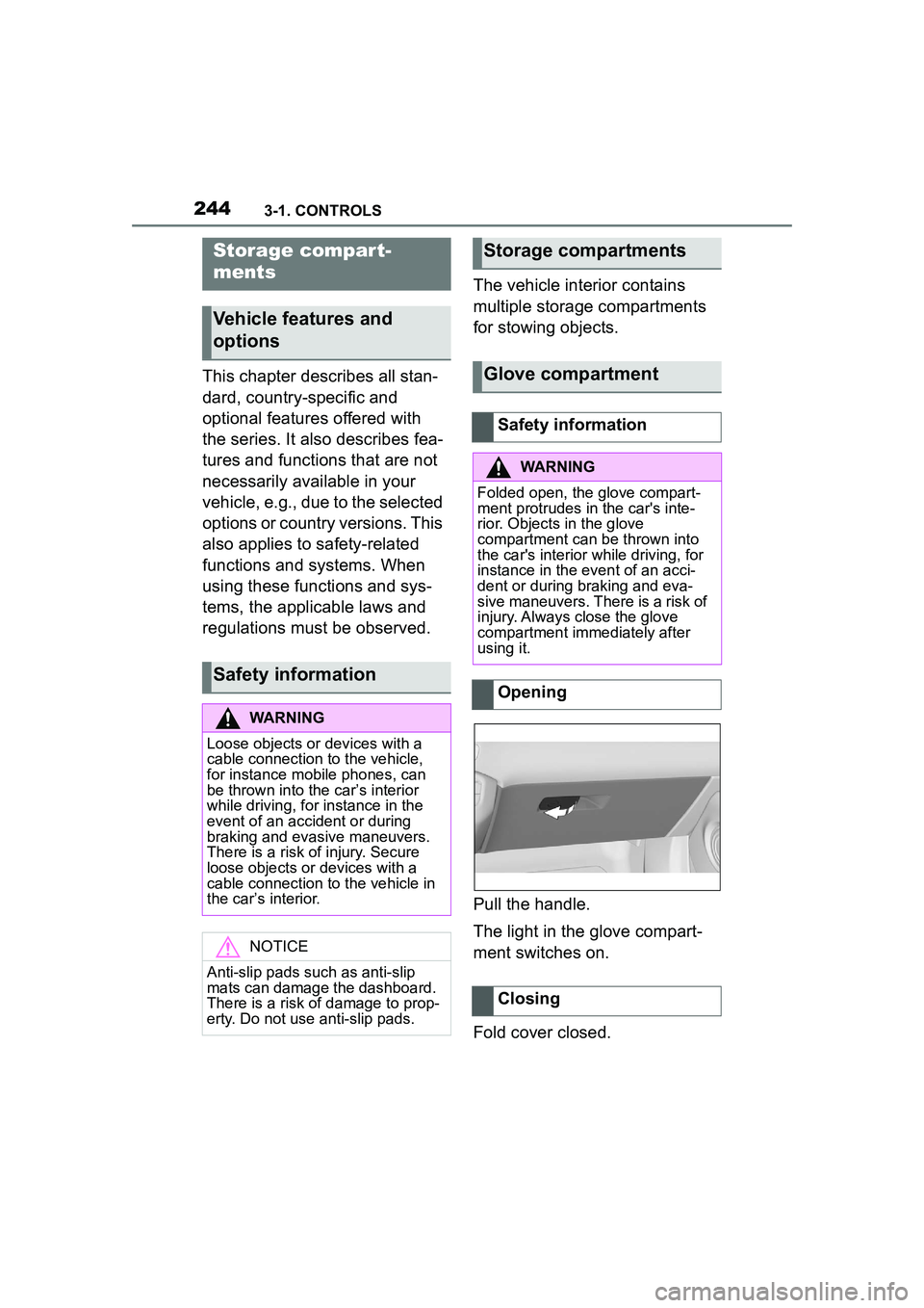
Pull the handle.
The light in the glove compart-
ment switches on.
Fold cover closed.
Storage compar t-
ments
Vehicle features and
options
Safety information
WARNING
Loose objects or devices with a
cable connection to the vehicle,
for instance mobile phones, can
be thrown into the car’s interior
while driving, for instance in the
event of an accident or during
braking and evasive maneuvers.
There is a risk of injury. Secure
loose objects or devices with a
cable connection to the vehicle in
the car’s interior.
NOTICE
Anti-slip pads such as anti-slip
mats can damage the dashboard.
There is a risk of damage to prop-
erty. Do not use anti-slip pads.
Storage compartments
Glove compartment
Safety information
WARNING
Folded open, the glove compart-
ment protrudes in the car's inte-
rior. Objects in the glove
compartment can
be thrown into
the car's interior while driving, for
instance in the event of an acci-
dent or during braking and eva-
sive maneuvers. There is a risk of
injury. Always close the glove
compartment immediately after
using it.
Opening
Closing
Page 245 of 356
2453-1. CONTROLS
3
CONTROLS
The glove compartment can be
locked with an integrated key,
refer to page 83. This prevents
access to the glove compart-
ment.
After the glove compartment is
locked, the remote control can
be handed over without the inte-
grated key, for instance when
the vehicle is parked by valet
parking.
There are storage compart-
ments in the doors.Locking
Compartments in the
doors
General information
Safety information
WARNING
Breakable objects, such as glass
bottles or glasses, can break in
the event of an accident or a brak-
ing or evasive maneuver. Broken
glass can be scattered in the car's
interior. There is a risk of injury or
risk of damage to property. Do not
use any breakable objects while
driving. Only stow breakable
objects in closed storage com-
partments.
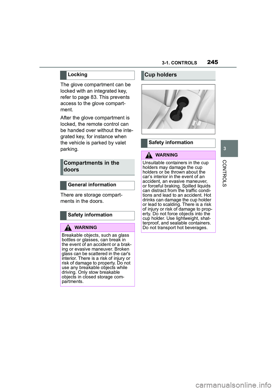
Cup holders
Safety information
WARNING
Unsuitable containers in the cup
holders may damage the cup
holders or be thrown about the
car’s interior in the event of an
accident, an evasive maneuver,
or forceful braking. Spilled liquids
can distract from the traffic condi-
tions and lead to an accident. Hot
drinks can damage the cup holder
or lead to scalding. There is a risk
of injury or risk of damage to prop-
erty. Do not force objects into the
cup holder. Use lightweight, shat-
terproof, and sealable containers.
Do not transport hot beverages.
Page 247 of 356
2473-1. CONTROLS
3
CONTROLS
3Subtract the combined
weight of the driver and pas-
sengers from XXX kg or XXX
lbs.
4 The resulting figure equals
the available amount of cargo
and luggage load capacity.
For example, if the “XXX”
amount equals 1,400 lbs and
there will be five 150 lbs pas-
sengers in your vehicle, the
amount of available cargo
and luggage load capacity is
650 lbs (1,400–750 (5 x 150)
= 650 lbs).
5 Determine the combined
weight of luggage and cargo
being loaded on the vehicle.
That weight may not safely
exceed the available cargo
and luggage load capacity
calculated in Step 4.
6 If your vehicle will be towing
a trailer, load from your trailer
will be transferred to your
vehicle. Consult this manual
to determine how this
reduces the available cargo
and luggage load capacity of
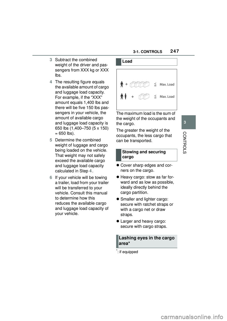
your vehicle. The maximum load is the sum of
the weight of the occupants and
the cargo.
The greater the weight of the
occupants, the less cargo that
can be transported.
Cover sharp edges and cor-
ners on the cargo.
Heavy cargo: stow as far for-
ward and as low as possible,
ideally directly behind the
cargo partition.
Smaller and lighter cargo:
secure with ratchet straps or
with a cargo net or draw
straps.
Larger and heavy cargo:
secure with cargo straps.
*: if equipped
Load
Stowing and securing
cargo
Lashing eyes in the cargo
area*
Page 248 of 356
2483-1. CONTROLS
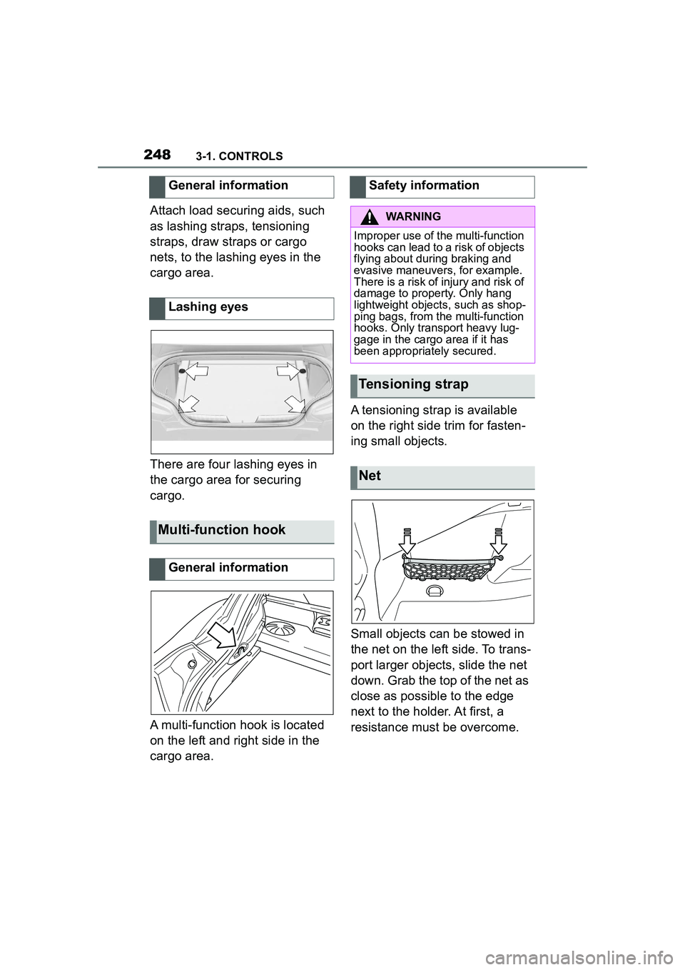
Attach load securing aids, such
as lashing straps, tensioning
straps, draw straps or cargo
nets, to the lashing eyes in the
cargo area.
There are four lashing eyes in
the cargo area for securing
cargo.
A multi-function hook is located
on the left and right side in the
cargo area.A tensioning strap is available
on the right side trim for fasten-
ing small objects.
Small objects can be stowed in
the net on the left side. To trans-
port larger objects, slide the net
down. Grab the top of the net as
close as possible to the edge
next to the holder. At first, a
resistance must be overcome.
General information
Lashing eyes
Multi-function hook
General information
Safety information
WARNING
Improper use of the multi-function
hooks can lead to a risk of objects
flying about during braking and
evasive maneuvers, for example.
There is a risk of injury and risk of
damage to property. Only hang
lightweight objects, such as shop-
ping bags, from the multi-function
hooks. Only transport heavy lug-
gage in the cargo area if it has
been appropriately secured.
Tensioning strap
Net
Page 249 of 356
2493-1. CONTROLS
3
CONTROLS
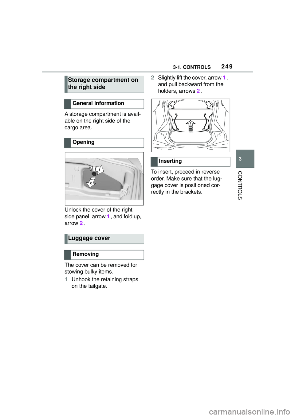
A storage compartment is avail-
able on the right side of the
cargo area.
Unlock the cover of the right
side panel, arrow 1, and fold up,
arrow 2.
The cover can be removed for
stowing bulky items.
1 Unhook the retaining straps
on the tailgate. 2
Slightly lift the cover, arrow 1,
and pull backward from the
holders, arrows 2.
To insert, proceed in reverse
order. Make sure that the lug-
gage cover is positioned cor-
rectly in the brackets.
Storage compartment on
the right side
General information
Opening
Luggage cover
Removing
Inserting