Page 23 of 678

21Pictorial index
Display ...............................................................................................P.93
When a warning message is displayed............................................P.480
Turn signal lever ............................................................................P.171
Headlight switch ............................................................................P.178
Headlights/front position lights/tail lights/daytime running lights ......P.178
Front fog lights*4/rear fog light .........................................................P.183
Windshield wiper and washer switch ..........................................P.184
Usage...............................................................................................P.184
Adding washer fluid..........................................................................P.428
Emergency flasher switch.............................................................P.462
Hood lock release lever .................................................................P.419
Tilt and telescopic steering lock release lever ............................P.131
Air conditioning system ........................................................P.380, 385
Usage.......................................................................................P.380, 385
Rear window defogger .............................................................P.381, 388
Audio system*4, 5...........................................................................P.326
*1: Vehicles without a smart entry & start system
*2: Vehicles with a smart entry & start system
*3: Vehicles with a Multidrive
*4: If equipped
*5: Vehicles with navigation/mu ltimedia system, refer to “Navigation and multimedia
system Owner’s manual” or “Multimedia Owner’s Manual”.
Page 24 of 678
22Pictorial index
■Switches (right-hand drive vehicles)
Tire pressure warning reset switch ..............................................P.442
S-IPA switch*..................................................................................P.288
Automatic High Beam switch .......................................................P.181
Headlight leveling dial ...................................................................P.180
Outside rear view mirror switches ...............................................P.133
Door lock switches ........................................................................ P.116
Power window switches ................................................................P.136
Window lock switch .......................................................................P.138
*: If equipped
Page 36 of 678

341-1. For safe use
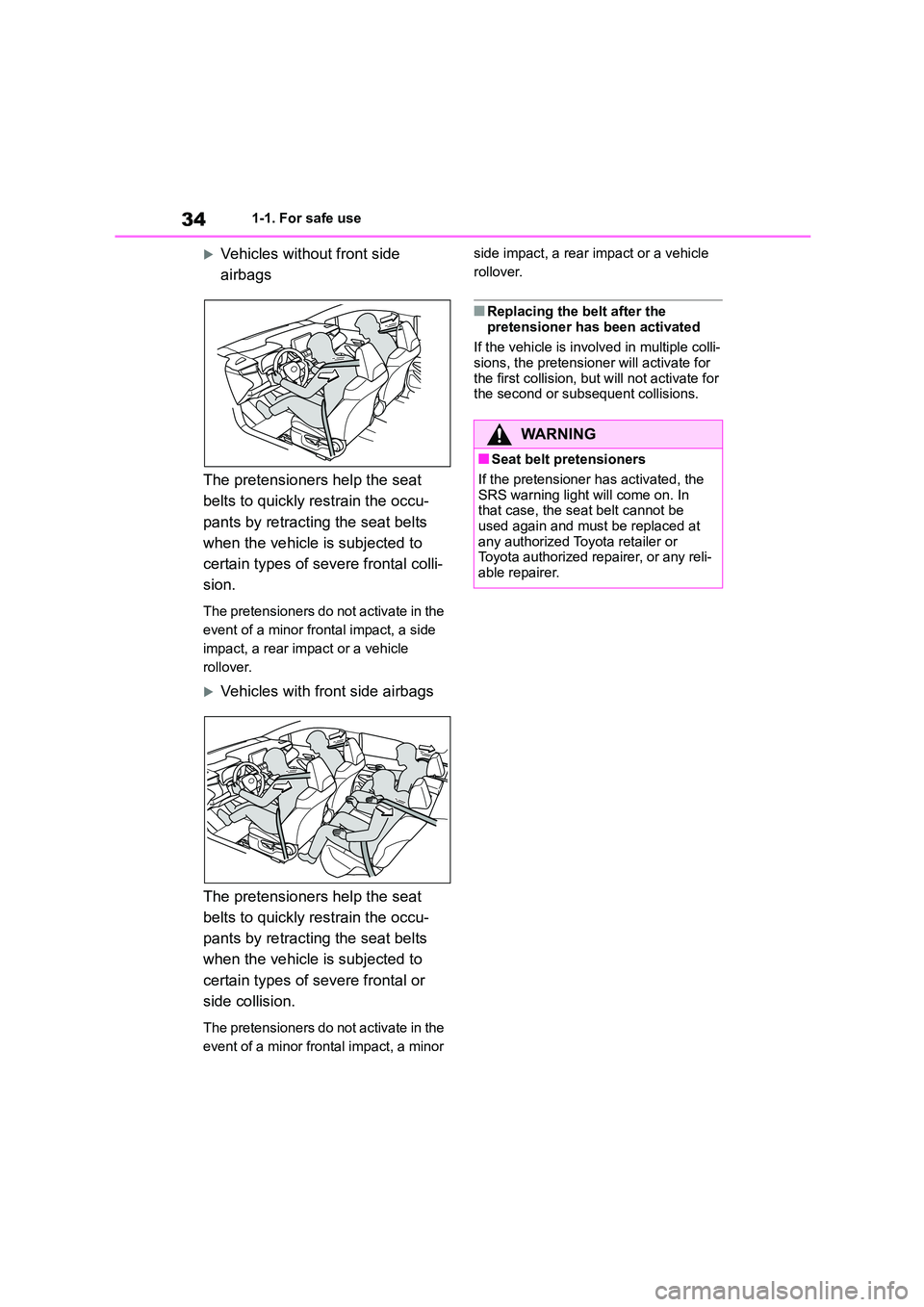
Vehicles without front side
airbags
The pretensioners help the seat
belts to quickly restrain the occu-
pants by retracting the seat belts
when the vehicle is subjected to
certain types of severe frontal colli-
sion.
The pretensioners do not activate in the
event of a minor frontal impact, a side
impact, a rear impact or a vehicle
rollover.
Vehicles with front side airbags
The pretensioners help the seat
belts to quickly restrain the occu-
pants by retracting the seat belts
when the vehicle is subjected to
certain types of severe frontal or
side collision.
The pretensioners do not activate in the
event of a minor frontal impact, a minor
side impact, a rear impact or a vehicle
rollover.
■Replacing the belt after the
pretensioner has been activated
If the vehicle is involved in multiple colli-
sions, the pretensioner will activate for
the first collision, but will not activate for the second or subsequent collisions.
WA R N I N G
■Seat belt pretensioners
If the pretensioner has activated, the
SRS warning light will come on. In that case, the seat belt cannot be
used again and must be replaced at
any authorized Toyota retailer or Toyota authorized repairer, or any reli-
able repairer.
Page 38 of 678
361-1. For safe use
Can help protect primarily the head of occupants in the outer seats
■SRS airbag system components
Seat belt pretensioners and force limiters (if equipped)
Side impact sensors (front) (if equipped)
Airbag manual on-off switch
Front passenger airbag
Side airbags (if equipped)
Curtain shield airbags (if equipped)
Side impact sensors (rear) (if equipped)
SRS warning light
Side impact sensors (front door) (if equipped)
Driver airbag
Driver’s knee airbag (if equipped)
“AIR BAG ON” and “AIR BAG OFF” indicator lights
Front impact sensors
Airbag sensor assembly
The main SRS airbag system components are shown above. The SRS
airbag system is controlled by the airbag sensor assembly. As the airbags
deploy, a chemical reaction in the inflators quickly fills the airbags with
non-toxic gas to help restrain the motion of the occupants.
■If the SRS airbags deploy (inflate)●Slight abrasions, burns, bruising etc.,
Page 70 of 678

681-3. Emergency assistance
2Server activates the service in the DCM and defines which vehicle data
to collect.
3 Defined vehicle data is collected by the DCM.
4 Data is shared with the server.
5 Data is stored in the server.
6 Data is processed in the server for fulfilling the service.
7 Processed data is presented to the customer.
For a list of eligible service please visit the Toyota Customer portal.
Implementing Regulation
Implementing Regulation Annex1 PART3 User InformationConformity
1. DESCRIPTION OF THE ECALL IN-VEHICLE SYSTEM
1.1.Overview of the 112-based eCall in-vehicle sys-
tem, its operation and functionalitiesO
1.2.
The 112-based eCall service is a public service
of general interest and is accessible free of
charge.
O
1.3.
The 112-based eCall in-vehicle system is acti-
vated by default. It is activated automatically by
means of in-vehicle sensors in the event of a
severe accident. It will also be triggered automat-
ically when the vehicle is equipped with a TPS
system which does not function in the event of a
severe accident.
O
1.4.
The 112-based eCall in-vehicle system can also
be triggered manually, if needed. Instructions for
manual activation of the system
O
1.5.
In the event of a critical system failure that would
disable the 112-based eCall in-vehicle system,
the following warning will be given to the occu-
pants of the vehicle
O
2. INFORMATION ON DATA PROCESSING
Page 81 of 678
2
79
2
Vehicle status information and indicators
Vehicle status information
and indicators
.2-1. Instrument cluster
Warning lights and indicators
......................................... 80
Gauges and meters (4.2-inch
display) ............................. 85
Gauges and meters (7-inch
display) ............................. 88
Multi-information display ..... 93
Head-up display................ 100
Fuel consumption information
....................................... 104
Page 82 of 678
802-1. Instrument cluster
2-1.Instrument cluster
For the purpose of explanation, the following illustrations display all warning
lights and indicators illuminated.
4.2-inch display
7-inch display (when analog speedometer is displayed)
War ning lights and indicators
The warning lights and indicators on the instrument cluster, center
panel and outside rear view mirrors inform the driver of the status of
the vehicle’s various systems.
Warning lights and indicators displayed on the instrument
cluster
Page 83 of 678
81
2
2-1. Instrument cluster
Vehicle status information and indicators
7-inch display (when digital speedometer is displayed)
7-inch display (when digital+ speedometer is displayed) (if equipped)
Warning lights inform the driver of
malfunctions in the indicated vehi-
cle’s systems.
Warning lights
(Red)
Brake system warning light*1
( P.471)
(Yellow)
Brake system warning light*1
( P.471)
High coolant temperature
warning light*1, 2 ( P.471)
Charging system warning
light*1 ( P.472)
Low engine oil pressure
warning light*1, 2 ( P.472)
Malfunction indicator lamp*1
( P.472)
SRS warning light*1 ( P.472)