2022 RAM PROMASTER CITY wheel
[x] Cancel search: wheelPage 179 of 260
IN CASE OF EMERGENCY177
7. Lower the vehicle by turning the jack screw to the left Ú page 236.
8. Lower the jack to its fully-closed position.
9. Stow the cable and wheel spacer before driving the vehicle Ú page 177.
10. Stow the jack and tools under the driver’s seat.
11. Check the spare tire pressure as soon as possible. Correct the tire pressure, as
required.
12. When you place the spare tire back on the winch or if you carry the tire in need of repair
on the winch, always check that the tire is
properly secured under the vehicle by pushing
on the stowed tire under the rear fascia/
bumper at the back of the vehicle. If the tire
has motion when pushed, use the tools to
re-tighten the winch until a loud click is heard.
VEHICLES WITH ALLOY WHEELS
For stowing a damaged tire on vehicles with alloy
wheels, remove the adapter bracket and bolts
from the storage bag in the glove compartment
and follow the steps below:
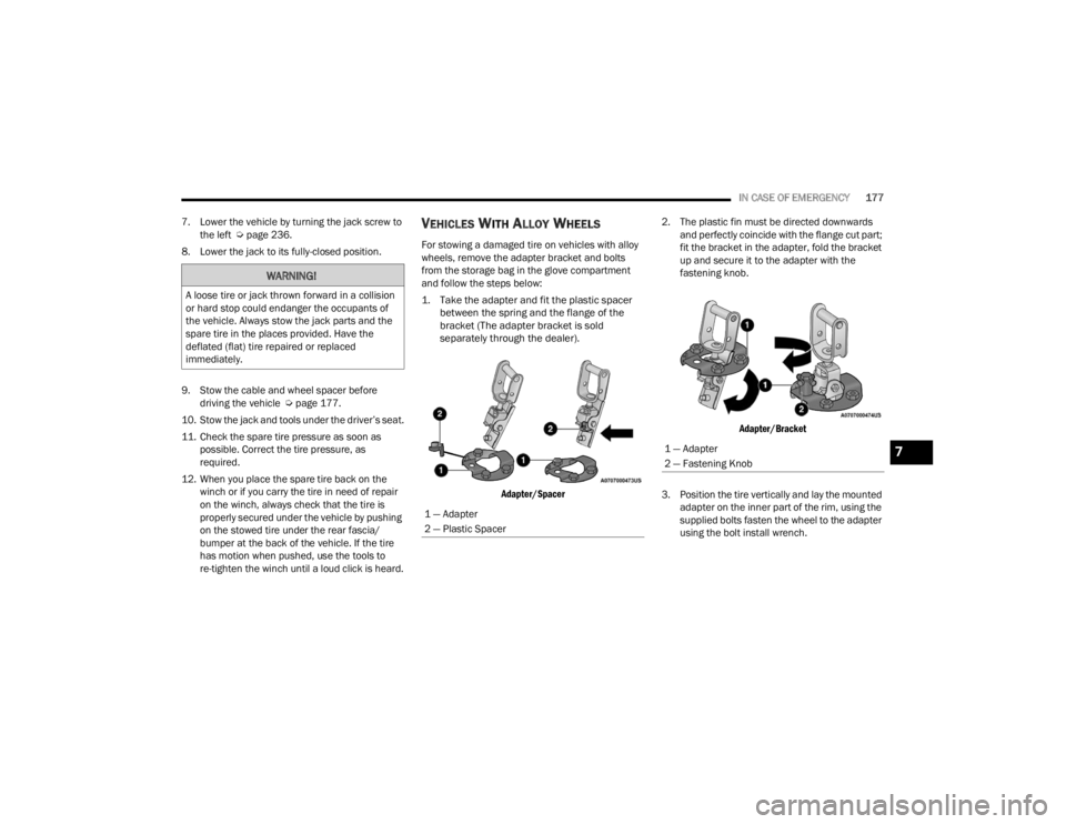
1. Take the adapter and fit the plastic spacer between the spring and the flange of the
bracket (The adapter bracket is sold
separately through the dealer).
Adapter/Spacer
2. The plastic fin must be directed downwards
and perfectly coincide with the flange cut part;
fit the bracket in the adapter, fold the bracket
up and secure it to the adapter with the
fastening knob.
Adapter/Bracket
3. Position the tire vertically and lay the mounted adapter on the inner part of the rim, using the
supplied bolts fasten the wheel to the adapter
using the bolt install wrench.
WARNING!
A loose tire or jack thrown forward in a collision
or hard stop could endanger the occupants of
the vehicle. Always stow the jack parts and the
spare tire in the places provided. Have the
deflated (flat) tire repaired or replaced
immediately.
1 — Adapter
2 — Plastic Spacer
1 — Adapter
2 — Fastening Knob7
22_VM_OM_EN_USC_t.book Page 177
Page 180 of 260

178IN CASE OF EMERGENCY
Alloy Wheel Mounting
4. Tighten the bolts with the wrench handle.
5. Rotate the winch mechanism clockwise until the wheel is properly stowed under the vehicle
and until the wench makes three audible
noises.
6. Reach underneath and shake tire by hand to confirm that it is secure. The tire should not
move. If the tire is still loose and/or three
audible noises are not heard, place and secure
damaged wheel into the vehicle and seek
dealer assistance for the winch mechanism.
VEHICLES EQUIPPED WITH WHEEL
C
OVERS
1. Mount the road tire on the axle.
2. To ease the installation process for steel
wheels with wheel covers, install two wheel
bolts on the wheel. Install the wheel bolts with
the threaded end of the bolt toward the wheel.
Lightly tighten the wheel bolts.
Tire And Wheel Cover Or Center Cap
3. Align the valve notch in the wheel cover with
the valve stem on the wheel. Install the cover
by hand, snapping the cover over the two
wheel bolts. Do not use a hammer or excessive
force to install the cover.
4. Install the remaining wheel bolts with the threaded end of the wheel bolt toward the
wheel. Lightly tighten the wheel bolts.
5. Lower the vehicle to the ground by turning the jack handle counterclockwise.
6. Finish tightening the wheel bolts. Push down on the wrench while holding at the end of the
handle for increased leverage. Tighten the
wheel bolts in a star pattern until each wheel
bolt has been tightened twice Ú page 236.
7. After 25 miles (40 km) check the wheel bolt torque with a torque wrench to ensure that all
wheel bolts are properly seated against the
wheel.
1 — Valve Stem
2 — Valve Notch
3 — Road Tire
4 — Wheel Cover
5 — Wheel Lug Nut
WARNING!
To avoid the risk of forcing the vehicle off the
jack, do not fully tighten the wheel bolts until the
vehicle has been lowered. Failure to follow this
warning may result in serious injury.
22_VM_OM_EN_USC_t.book Page 178
Page 181 of 260
IN CASE OF EMERGENCY179
(Continued)
TIRE SERVICE KIT — IF EQUIPPED
Small punctures up to ¼ inch (6 mm) in the tire
tread can be sealed with Tire Service Kit. Foreign
objects (e.g., screws or nails) should not be
removed from the tire. Tire Service Kit can be used
in outside temperatures down to approximately
-4°F (-20°C).
This kit will provide a temporary tire seal, allowing
you to drive your vehicle up to 100 miles (160 km)
with a maximum speed of 50 mph (80 km/h).
TIRE SERVICE KIT STORAGE
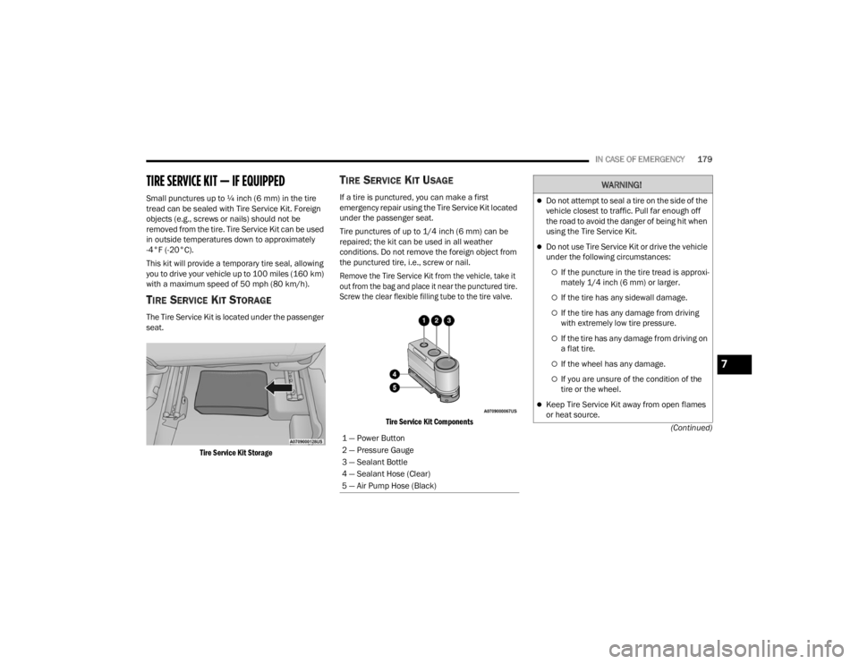
The Tire Service Kit is located under the passenger
seat.
Tire Service Kit Storage
TIRE SERVICE KIT USAGE
If a tire is punctured, you can make a first
emergency repair using the Tire Service Kit located
under the passenger seat.
Tire punctures of up to 1/4 inch (6 mm) can be
repaired; the kit can be used in all weather
conditions. Do not remove the foreign object from
the punctured tire, i.e., screw or nail.
Remove the Tire Service Kit from the vehicle, take it
out from the bag and place it near the punctured tire.
Screw the clear flexible filling tube to the tire valve.
Tire Service Kit Components
1 — Power Button
2 — Pressure Gauge
3 — Sealant Bottle
4 — Sealant Hose (Clear)
5 — Air Pump Hose (Black)
WARNING!
Do not attempt to seal a tire on the side of the
vehicle closest to traffic. Pull far enough off
the road to avoid the danger of being hit when
using the Tire Service Kit.
Do not use Tire Service Kit or drive the vehicle
under the following circumstances:
If the puncture in the tire tread is approxi -
mately 1/4 inch (6 mm) or larger.
If the tire has any sidewall damage.
If the tire has any damage from driving
with extremely low tire pressure.
If the tire has any damage from driving on
a flat tire.
If the wheel has any damage.
If you are unsure of the condition of the
tire or the wheel.
Keep Tire Service Kit away from open flames
or heat source.
7
22_VM_OM_EN_USC_t.book Page 179
Page 186 of 260
184IN CASE OF EMERGENCY
IGNITION KEY REMOVAL OVERRIDE
This vehicle is equipped with a Key Ignition Park
Interlock which requires the transmission to be in
PARK (P) before the ignition switch can be turned
to the STOP (key removal) position.
To remove the key manually, proceed as follows:
1. Firmly apply the parking brake.
2. Remove the Allen Key located in the rear cargo
area, in the tool bag (if equipped) or on the left
side in the cargo box.
3. Unlock the steering column, pull the tilt/ telescoping control handle down.
4. Pull the steering wheel outward until it is in the end of the travel position, then lock the
steering column in position, push the control
handle up until fully engaged.
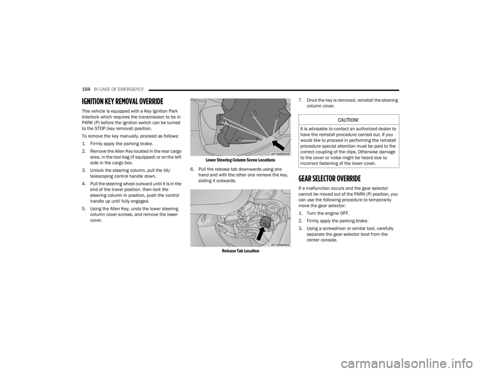
5. Using the Allen Key, undo the lower steering column cover screws, and remove the lower
cover.
Lower Steering Column Screw Locations
6. Pull the release tab downwards using one hand and with the other one remove the key,
sliding it outwards.
Release Tab Location
7. Once the key is removed, reinstall the steering
column cover.
GEAR SELECTOR OVERRIDE
If a malfunction occurs and the gear selector
cannot be moved out of the PARK (P) position, you
can use the following procedure to temporarily
move the gear selector:
1. Turn the engine OFF.
2. Firmly apply the parking brake.
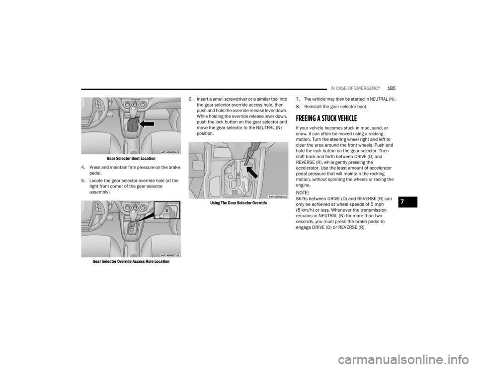
3. Using a screwdriver or similar tool, carefully separate the gear selector boot from the
center console.
CAUTION!
It is advisable to contact an authorized dealer to
have the reinstall procedure carried out. If you
would like to proceed in performing the reinstall
procedure special attention must be paid to the
correct coupling of the clips. Otherwise damage
to the cover or noise might be heard due to
incorrect fastening of the lower cover.
22_VM_OM_EN_USC_t.book Page 184
Page 187 of 260
IN CASE OF EMERGENCY185
Gear Selector Boot Location
4. Press and maintain firm pressure on the brake pedal.
5. Locate the gear selector override hole (at the right front corner of the gear selector
assembly).
Gear Selector Override Access Hole Location
6. Insert a small screwdriver or a similar tool into
the gear selector override access hole, then
push and hold the override release lever down.
While holding the override release lever down,
push the lock button on the gear selector and
move the gear selector to the NEUTRAL (N)
position.
Using The Gear Selector Override 7. The vehicle may then be started in NEUTRAL (N).
8. Reinstall the gear selector boot.
FREEING A STUCK VEHICLE
If your vehicle becomes stuck in mud, sand, or
snow, it can often be moved using a rocking
motion. Turn the steering wheel right and left to
clear the area around the front wheels. Push and
hold the lock button on the gear selector. Then
shift back and forth between DRIVE (D) and
REVERSE (R), while gently pressing the
accelerator. Use the least amount of accelerator
pedal pressure that will maintain the rocking
motion, without spinning the wheels or racing the
engine.
NOTE:
Shifts between DRIVE (D) and REVERSE (R) can
only be achieved at wheel speeds of 5 mph
(8 km/h) or less. Whenever the transmission
remains in NEUTRAL (N) for more than two
seconds, you must press the brake pedal to
engage DRIVE (D) or REVERSE (R).
7
22_VM_OM_EN_USC_t.book Page 185
Page 188 of 260
186IN CASE OF EMERGENCY
NOTE:Push the ESC OFF button, to place the Electronic
Stability Control (ESC) system in Partial Off mode,
before rocking the vehicle Ú page 132. Once the
vehicle has been freed, push the ESC OFF button
again to restore ESC On mode.CAUTION!
Racing the engine or spinning the wheels may
lead to transmission overheating and failure.
Allow the engine to idle with the transmission in
NEUTRAL for at least one minute after every five
rocking-motion cycles. This will minimize
overheating and reduce the risk of transmission
failure during prolonged efforts to free a stuck
vehicle.
WARNING!
Fast spinning tires can be dangerous. Forces
generated by excessive wheel speeds may
cause damage, or even failure, of the axle and
tires. A tire could explode and injure someone.
Do not spin your vehicle's wheels faster than
30 mph (48 km/h) or for longer than 30
seconds continuously without stopping when
you are stuck and do not let anyone near a
spinning wheel, no matter what the speed.
CAUTION!
When “rocking” a stuck vehicle by shifting
between DRIVE and REVERSE, do not spin the
wheels faster than 15 mph (24 km/h), or
drivetrain damage may result.
Revving the engine or spinning the wheels too
fast may lead to transmission overheating and
failure. It can also damage the tires. Do not spin
the wheels above 30 mph (48 km/h) while in
gear (no transmission shifting occurring).
22_VM_OM_EN_USC_t.book Page 186
Page 189 of 260

IN CASE OF EMERGENCY187
TOWING A DISABLED VEHICLE
This section describes procedures for towing a disabled vehicle using a commercial towing service.
Towing Condition Wheel OFF The Ground ALL MODELS
Flat Tow NONENOT ALLOWED
Wheel Lift Or Dolly Tow Front
OK
Rear NOT ALLOWED
Flatbed ALLBEST METHOD
7
22_VM_OM_EN_USC_t.book Page 187
Page 190 of 260

188IN CASE OF EMERGENCY
Proper towing or lifting equipment is required to
prevent damage to your vehicle. Use only tow bars
and other equipment designed for this purpose,
following equipment manufacturer’s instructions.
Use of safety chains is mandatory. Attach a tow bar
or other towing device to main structural members
of the vehicle, not to fascia/bumpers or associated
brackets. State and local laws regarding vehicles
under tow must be observed.
If you must use the accessories (wipers,
defrosters, etc.) while being towed, the ignition
must be in the ON/RUN mode.
If the ignition key is unavailable, or the vehicle's
battery is discharged, for instructions on shifting
the transmission out of PARK (P) for towing
Ú page 184. FCA US LLC recommends towing your vehicle with
all four wheels OFF the ground using a flatbed.
NOTE:If flatbed equipment is not available, this vehicle
must be towed with the front wheels OFF the
ground (using a towing dolly, or wheel lift
equipment with the front wheels raised).
ENHANCED ACCIDENT RESPONSE SYSTEM
(EARS)
This vehicle is equipped with an Enhanced
Accident Response System.
This feature is a communication network that
takes effect in the event of an impact
Úpage 150.
EVENT DATA RECORDER (EDR)
This vehicle is equipped with an event data
recorder (EDR). The main purpose of an EDR is to
record data that will assist in understanding how a
vehicle’s systems performed under certain crash
or near crash-like situations, such as an air bag
deployment or hitting a road obstacle Úpage 151.
CAUTION!
Do not use sling type equipment when towing.
Vehicle damage may occur.
When securing the vehicle to a flat bed truck,
do not attach to front or rear suspension
components. Damage to your vehicle may
result from improper towing.
CAUTION!
Towing this vehicle in violation of the above
requirements can cause severe transmission
damage. Damage from improper towing is not
covered under the New Vehicle Limited
Warranty.
22_VM_OM_EN_USC_t.book Page 188