Page 105 of 312

STARTING AND OPERATING103
becomes inactive. When the vehicle is moving
forward, the system will remain active until the
vehicle speed remains below approximately
11 mph (18 km/h). Reducing the speed
approximately below 9 mph (15 km/h), the system
will come back active. When the vehicle is moving
in REVERSE, the system will remain active as long
as the speed remains below the maximum
operating speed of 7 mph (11 km/h). When the
maximum speed limit is exceeded, the system is
disabled and the Park Assist switch LED will
illuminate. The system will become active again if
the vehicle speed reduces below approximately
6 mph (9 km/h).
PARK ASSIST SENSORS
The four Park Assist sensors, located in the rear
fascia/bumper, monitor the area behind the
vehicle that is within the sensors’ field of view. The
sensors can detect obstacles from approximately
12 inches (30 cm) up to 59 inches (150 cm) from
the rear fascia/bumper in the horizontal direction,
depending on the location, type and orientation of
the obstacle. The four Park Assist sensors, located in the front
fascia/bumper (if equipped), monitor the area in
front of the vehicle that is within the sensors’ field
of view. The sensors can detect obstacles from
approximately 12 inches (30 cm) up to 39 inches
(100 cm) from the front fascia/bumper in the
horizontal direction, depending on the location,
type and orientation of the obstacle.
PARK ASSIST WARNING DISPLAY
The Park Assist Warning screen will only be
displayed if “Sound and Display” is selected from
the Uconnect system Ú page 123.
The Park Assist Warning screen is located within
the instrument cluster display. It provides visual
warnings to indicate the distance between the rear
fascia/bumper and/or front fascia/bumper and
the detected obstacle Ú page 64.
PARK ASSIST DISPLAY
The Park Assist warning screen will be displayed
when an obstacle is detected while the vehicle is in
DRIVE or REVERSE, as long as the vehicle speed is
below 7 mph (11 km/h) when in REVERSE and
below 11 mph (18 km/h) when in DRIVE. When the
vehicle is in REVERSE, the Park Assist warning
screen will always be displayed.
The system will indicate a detected obstacle by
showing a single arc in the left and/or right front or
rear regions based on the object’s distance and
location relative to the vehicle.
If an object is detected in the left and/or right front
or rear region, the display will show a single arc in
the left and/or right front or rear region and the
system will produce a tone. As the vehicle moves
closer to the object, the display will show the single
arc moving closer to the vehicle and the tone will
change from a single 1/2 second tone to slow, to
fast, to continuous.
4
22_FD_OM_EN_USC_t.book Page 103
Page 106 of 312
104STARTING AND OPERATING
Front/Rear/Side ParkSense Arcs
1 — Slow Tone/Flashing Arc 6 — Fast Tone/Flashing Arc
2 — Fast Tone/Flashing Arc 7 — Fast Tone/Flashing Arc
3 — Fast Tone/Flashing Arc 8 — Slow Tone/Solid Arc
4 — Continuous Tone/Flashing Arc 9 — Slow Tone/Solid Arc
5 — Continuous Tone/Flashing Arc 10 — Slow Tone/Solid Arc
22_FD_OM_EN_USC_t.book Page 104
Page 107 of 312

STARTING AND OPERATING105
The vehicle is close to the obstacle when the warning display shows one flashing arc and sounds a continuous tone. The following charts show the warning alert
operation when the system is detecting an obstacle:
NOTE:Park Assist will reduce the volume of the radio, if on, when the system is sounding an audible tone.
WARNING ALERTS FOR REAR
Rear Distance (inches/cm) Greater than
59 inches (150 cm) 59-52 inches
(150-130 cm) 52-41 inches
(130-105 cm) 41-34 inches
(105-85 cm) 34-24 inches
(85-60 cm) 24-12 inches
(60-30 cm) Less than
12 inches (30 cm)
Arcs — Left NoneNoneNoneNoneNone 6th Flashing 5th Flashing
Arcs — Center None10th Solid 9th Solid 8th Solid 7th Flashing 6th Flashing 5th Flashing
Arcs — Right NoneNoneNoneNoneNone 6th Flashing 5th Flashing
Audible Alert Chime None Audible chime increases as the object gets closer to the vehicle Continuous
Radio Volume Reduced No
Yes
WARNING ALERTS FOR FRONT
Front Distance
(inches/cm) Greater than
39 inches (100 cm) 39-32 inches
(100-80 cm) 32-24 inches
(80-60 cm) 24-12 inches
(60-30 cm) Less than 12 inches
(30 cm)
Arcs — Left NoneNoneNone3rd Flashing 4th Flashing
Arcs — Center None1st Solid2nd Flashing 3rd Flashing4th Flashing
Arcs — Right NoneNoneNone3rd Flashing 4th Flashing
Audible Alert Chime NoneAudible chime increases as the object gets close to the vehicle Continuous
Radio Volume Reduced No Yes
4
22_FD_OM_EN_USC_t.book Page 105
Page 108 of 312

106STARTING AND OPERATING
Front Park Assist Audible Alerts
Park Assist will turn off the Front Park Assist
audible alert (chime) after approximately three
seconds when an obstacle has been detected, the
vehicle is stationary, and brake pedal is applied. If
the obstacle has been detected within less than
12 inches (30 cm), then the Park Assist will not
turn off the Front Park Assist audible alert.
Adjustable Chime Volume Settings
Front and Rear chime volume settings can be
selected from the Customer-Programmable
Features section of the Uconnect system
Ú page 123.
If the Uconnect system is equipped, chime volume
settings will not be accessible from the instrument
cluster display.
The chime volume settings include low, medium,
and high.
Park Assist will retain its last known configuration
state through ignition cycles.
ENABLING AND DISABLING PARK
A
SSIST
Park Assist can be enabled and disabled
with the Park Assist switch, located on
the switch panel below the Uconnect
display. When the Park Assist switch is pushed to disable
the system, the instrument cluster display will
show the “Park Assist Disabled” message for
approximately five seconds Ú
page 64.
The Park Assist switch LED will be on when the
Park Assist system is disabled or requires service.
The Park Assist switch LED will be off when the
system is enabled. If the Park Assist switch is
pushed, and the system requires service, the Park
Assist switch LED will blink momentarily, and then
the LED will be on.
SERVICE THE PARK ASSIST SYSTEM
During vehicle start up, when the Park Assist System
has detected a faulted condition, the instrument
cluster display will actuate a single chime, once per
ignition cycle, and it will show the "PARK ASSIST
UNAVAILABLE WIPE REAR SENSORS", "PARK ASSIST
UNAVAILABLE WIPE FRONT SENSORS", or the "PARK
ASSIST UNAVAILABLE SERVICE REQUIRED" message
for five seconds.
If "PARK ASSIST UNAVAILABLE WIPE REAR
SENSORS" or "PARK ASSIST UNAVAILABLE WIPE
FRONT SENSORS" appears in the instrument
cluster display make sure the outer surface and
the underside of the rear fascia/bumper and/or
front fascia/bumper is clean and clear of snow,
ice, mud, dirt or other obstruction and then cycle
the ignition. If the message continues to appear
see an authorized dealer. If the "PARK ASSIST UNAVAILABLE SERVICE
REQUIRED" message appears in the instrument
cluster display, see an authorized dealer.
CLEANING THE PARK ASSIST SYSTEM
Clean the Park Assist sensors with water, car wash
soap and a soft cloth. Do not use rough or hard
cloths. Do not scratch or poke the sensors.
Otherwise, you could damage the sensors.
PARK ASSIST SYSTEM USAGE
P
RECAUTIONS
NOTE:
Ensure that the outer surface and the underside
of the front and rear fascia/bumper are clean
and clear of snow, ice, mud, dirt or other
obstruction to keep the Park Assist system oper -
ating properly.
Jackhammers, large trucks, and other vibra -
tions could affect the performance of Rear Park
Assist.
Clean the Park Assist sensors regularly, taking
care not to scratch or damage them. The
sensors must not be covered with ice, snow,
slush, mud, dirt or debris. Failure to do so can
result in the system not working properly. The
Park Assist system might not detect an obstacle
22_FD_OM_EN_USC_t.book Page 106
Page 109 of 312

STARTING AND OPERATING107
(Continued)
(Continued)
behind the fascia/bumper, or it could provide a
false indication that an obstacle is behind the
fascia/bumper.
Objects such as bicycle carriers, etc., must not
be placed within 12 inches (30 cm) from the
rear fascia/bumper while driving the vehicle.
Failure to do so can result in the system misin
-
terpreting a close object as a sensor problem,
causing a failure indication to be displayed in
the instrument cluster. If it is necessary to keep the trailer hitch and hitch
ball assembly mounted for a long period, it is
possible to filter out the trailer hitch and hitch ball
assembly presence within the sensor’s field of
view. The filtering operation must be performed
only by an authorized dealer.
WARNING!
Drivers must be careful when backing up even
when using Park Assist. Always check carefully
behind your vehicle, look behind you, and be
sure to check for pedestrians, animals, other
vehicles, obstructions, and blind spots before
backing up. You are responsible for safety and
must continue to pay attention to your
surroundings. Failure to do so can result in
serious injury or death.
Before using Park Assist, it is strongly recom
-
mended that the ball mount and hitch ball
assembly be disconnected from the vehicle
when the vehicle is not used for towing. Failure
to do so can result in injury or damage to vehi -
cles or obstacles because the hitch ball will be
much closer to the obstacle than the rear fascia
when the vehicle sounds the continuous tone.
Also, the sensors could detect the ball mount
and hitch ball assembly, depending on its size
and shape, giving a false indication that an
obstacle is behind the vehicle.
CAUTION!
Park Assist is only a parking aid and it is
unable to recognize every obstacle, including
small obstacles. Parking curbs might be
temporarily detected or not detected at all.
Obstacles located above or below the sensors
will not be detected when they are in close
proximity.
WARNING!
The vehicle must be driven slowly when using
Park Assist in order to be able to stop in time
when an obstacle is detected. It is recom -
mended that the driver looks over his/her
shoulder when using Park Assist.
CAUTION!
4
22_FD_OM_EN_USC_t.book Page 107
Page 110 of 312

108STARTING AND OPERATING
LANESENSE — IF EQUIPPED
LANESENSE OPERATION
The LaneSense system is operational at speeds
above 37 mph (60 km/h) and below 112 mph
(180 km/h). The LaneSense system uses a
forward looking camera to detect lane markings
and measure vehicle position within the lane
boundaries.
When both lane markings are detected and the
driver drifts out of the lane (no turn signal applied),
the LaneSense system provides a haptic warning
in the form of torque applied to the steering wheel
to prompt the driver to remain within the lane
boundaries. If the driver continues to drift out of
the lane, the LaneSense system provides a visual
warning through the instrument cluster display to
prompt the driver to remain within the lane
boundaries.
The driver may manually override the haptic
warning by applying force to the steering wheel at
any time.
When only a single lane marking is detected and
the driver drifts across the lane marking (no turn
signal applied), the LaneSense system provides a
visual warning through the instrument cluster display to prompt the driver to remain within the
lane. When only a single lane marking is detected,
a haptic (torque) warning will not be provided.NOTE:When operating conditions have been met, the
LaneSense system will monitor if the driver’s
hands are on the steering wheel and provides an
audible warning to the driver if removed. The
system will cancel if the driver does not return their
hands to the wheel.
TURNING LANESENSE ON OR OFF
The LaneSense button is located on the
end of the turn signal stalk, located on
the left side of the steering column.
To turn the LaneSense system on, push the
LaneSense button once. A “Lane Sense On”
message is shown in the instrument cluster
display.
To turn the LaneSense system off, push the
LaneSense button once.
NOTE:The LaneSense system will retain the last system
state (on or off) from the last ignition cycle when
the ignition is changed to the ON/RUN position.
LANESENSE WARNING MESSAGE
The LaneSense system will indicate the current
lane drift condition through the instrument cluster
display.
When the LaneSense system is on, the lane lines
are gray when both of the lane boundaries have
not been detected and the LaneSense telltale is
solid white.
System On (Gray Lines/White Telltale)
22_FD_OM_EN_USC_t.book Page 108
Page 111 of 312

STARTING AND OPERATING109
Left Lane Departure — Only Left Lane Detected
When the LaneSense system is on, the Lane-
Sense telltale is solid white when only the left
lane marking has been detected and the system
is ready to provide visual warnings in the instru -
ment cluster display if a lane departure occurs.
When the LaneSense system senses the lane
has been approached and is in a lane departure
situation, the left lane line flashes yellow
(on/off), and the LaneSense telltale changes
from solid white to flashing yellow.
Lane Approached (Flashing Yellow Line/ Flashing Yellow Telltale)
NOTE:The LaneSense system operates with similar
behavior for a right lane departure when only the
right lane marking has been detected. Left Lane Departure — Both Lanes Detected
When the LaneSense system is on, the lane
lines turn from gray to white to indicate that
both of the lane markings have been detected.
The LaneSense telltale is solid green when both
lane markings have been detected and the
system is “armed” to provide visual warnings in
the instrument cluster display and a torque
warning in the steering wheel if a lane departure
occurs.
Lanes Sensed (White Lines/Green Telltale)
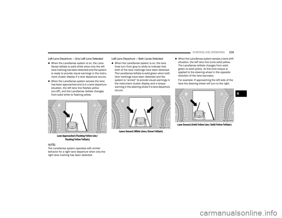
When the LaneSense system senses a lane drift
situation, the left lane line turns solid yellow.
The LaneSense telltale changes from solid
green to solid yellow. At this time torque is
applied to the steering wheel in the opposite
direction of the lane boundary.
For example: If approaching the left side of the
lane the steering wheel will turn to the right.
Lane Sensed (Solid Yellow Line/Solid Yellow Telltale)
4
22_FD_OM_EN_USC_t.book Page 109
Page 112 of 312

110STARTING AND OPERATING
When the LaneSense system senses the lane
has been approached and is in a lane departure
situation, the left lane line flashes yellow (on/
off). The LaneSense telltale changes from solid
yellow to flashing yellow. At this time torque is
applied to the steering wheel in the opposite
direction of the lane boundary.
For example: If approaching the left side of the
lane the steering wheel will turn to the right.
Lane Approached (Flashing Yellow Line/ Flashing Yellow Telltale)
NOTE:The LaneSense system operates with similar
behavior for a right lane departure.
CHANGING LANESENSE STATUS
The LaneSense system has settings to adjust the
intensity of the torque warning and the warning
zone sensitivity (early/late) that you can configure
through the Uconnect system screen Úpage 123.
NOTE:
When enabled the system operates above
37 mph (60 km/h) and below 112 mph
(180 km/h).
Use of the turn signal suppresses the warnings.
The system will not apply torque to the steering
wheel whenever a safety system engages.
(Anti-Lock Brakes, Traction Control System,
Electronic Stability Control, Full Brake Control
system, etc.).
PARKVIEW REAR BACK UP CAMERA
The ParkView Rear Back Up Camera allows you to
see an on-screen image of the rear surroundings of
your vehicle when the gear selector is put into
REVERSE. The image will be displayed on the
touchscreen display along with a note to “Check
Entire Surroundings” across the top of the screen.
After five seconds this note will disappear. The
ParkView camera is located on the rear of the
vehicle above the rear license plate.
Back Up Camera Location
When the vehicle is shifted out of REVERSE with
camera delay turned off, the rear camera mode is
exited and the navigation or audio screen appears
again.
When the vehicle is shifted out of REVERSE with
camera delay turned on, the camera image will
continue to be displayed for up to 10 seconds
unless the vehicle speed exceeds 8 mph (13 km/
h), the vehicle is shifted into PARK, or the ignition
is placed in the OFF position.
A touchscreen button to disable the camera is
available when the vehicle is not in REVERSE.
Display of the camera image after shifting out of
REVERSE can be disabled via Uconnect Settings.
When enabled, active guidelines are overlaid on
the image to illustrate the width of the vehicle and
its projected backup path based on the steering
wheel position.
22_FD_OM_EN_USC_t.book Page 110