2021 RAM PROMASTER CITY brake
[x] Cancel search: brakePage 171 of 280

SAFETY169
(Continued)
Maintaining Your Air Bag System Event Data Recorder (EDR)
This vehicle is equipped with an event data
recorder (EDR). The main purpose of an EDR is
to record, in certain crash or near crash-like
situations, such as an air bag deployment or
hitting a road obstacle, data that will assist in
understanding how a vehicle’s systems
performed. The EDR is designed to record data related to vehicle dynamics and safety systems
for a short period of time, typically 30 seconds
or less. The EDR in this vehicle is designed to
record such data as:
How various systems in your vehicle were
operating;
Whether or not the driver and passenger
safety belts were buckled/fastened;
How far (if at all) the driver was depressing
the accelerator and/or brake pedal; and,
How fast the vehicle was traveling.
This data can help provide a better
understanding of the circumstances in which
crashes and injuries occur.
NOTE:
EDR data are recorded by your vehicle only if a
non-trivial crash situation occurs; no data are
recorded by the EDR under normal driving
conditions and no personal data (e.g., name,
gender, age, and crash location) are recorded.
However, other parties, such as law enforce -
ment, could combine the EDR data with the type
of personally identifying data routinely acquired
during a crash investigation.
WARNING!
Modifications to any part of the air bag
system could cause it to fail when you need
it. You could be injured if the air bag system
is not there to protect you. Do not modify
the components or wiring, including adding
any kind of badges or stickers to the
steering wheel hub trim cover or the upper
passenger side of the instrument panel. Do
not modify the front fascia/bumper, vehicle
body structure, or add aftermarket side
steps or running boards.
It is dangerous to try to repair any part of
the air bag system yourself. Be sure to tell
anyone who works on your vehicle that it
has an air bag system.
Do not attempt to modify any part of your
air bag system. The air bag may inflate acci -
dentally or may not function properly if
modifications are made. Take your vehicle
to an authorized dealer for any air bag
system service. If your seat, including your
trim cover and cushion, needs to be
serviced in any way (including removal or
loosening/tightening of seat attachment
bolts), take the vehicle to an authorized
dealer. Only manufacturer approved seat
accessories may be used. If it is necessary
to modify the air bag system for persons
with disabilities, contact an authorized
dealer.
WARNING! (Continued)
6
21_VM_OM_EN_USC_t.book Page 169
Page 188 of 280

186SAFETY
(Continued)
(Continued)
Air Bag Warning Light
The Air Bag Warning Light will turn on for four
to eight seconds as a bulb check when the
ignition switch is first placed in the on ON/RUN
position. If the light is either not on during
starting, stays on, or turns on while driving, have
the system inspected at an authorized dealer as
soon as possible. After the bulb check, this light
will illuminate with a single chime when a fault
with the Air Bag System has been detected. It
will stay on until the fault is removed. If the light
comes on intermittently or remains on while
driving, have an authorized dealer service the
vehicle immediately Ú
page 153.
Defroster
Check operation by selecting the defrost mode
and place the blower control on high speed. You
should be able to feel the air directed against
the windshield. See an authorized dealer for
service if your defroster is inoperable.
Floor Mat Safety Information
Always use floor mats designed to fit your
vehicle. Only use a floor mat that does not
interfere with the operation of the accelerator,
brake or clutch pedals. Only use a floor mat that
is securely attached using the floor mat fasteners so it cannot slip out of position and
interfere with the accelerator, brake or clutch
pedals or impair safe operation of your vehicle
in other ways.
WARNING!
An improperly attached, damaged, folded, or
stacked floor mat, or damaged floor mat
fasteners may cause your floor mat to
interfere with the accelerator, brake, or clutch
pedals and cause a loss of vehicle control. To
prevent SERIOUS INJURY or DEATH:
ALWAYS securely attach your floor mat
using the floor mat fasteners. DO NOT
install your floor mat upside down or turn
your floor mat over. Lightly pull to confirm
mat is secured using the floor mat
fasteners on a regular basis.
ALWAYS REMOVE THE EXISTING FLOOR
MAT FROM THE VEHICLE before
installing any other floor mat. NEVER install
or stack an additional floor mat on top of an
existing floor mat.
ONLY install floor mats designed to fit your
vehicle. NEVER install a floor mat that
cannot be properly attached and secured to
your vehicle. If a floor mat needs to be
replaced, only use a FCA approved floor
mat for the specific make, model, and year
of your vehicle.
ONLY use the driver’s side floor mat on the
driver’s side floor area. To check for inter
-
ference, with the vehicle properly parked
with the engine off, fully depress the accel -
erator, the brake, and the clutch pedal (if
present) to check for interference. If your
floor mat interferes with the operation of
any pedal, or is not secure to the floor,
remove the floor mat from the vehicle and
place the floor mat in your trunk.
ONLY use the passenger’s side floor mat on
the passenger’s side floor area.
ALWAYS make sure objects cannot fall or
slide into the driver’s side floor area when
the vehicle is moving. Objects can become
trapped under accelerator, brake, or clutch
pedals and could cause a loss of vehicle
control.
WARNING! (Continued)
21_VM_OM_EN_USC_t.book Page 186
Page 189 of 280

SAFETY187
Periodic Safety Checks You Should Make
Outside The Vehicle
Tires
Examine tires for excessive tread wear and
uneven wear patterns. Check for stones, nails,
glass, or other objects lodged in the tread or
sidewall. Inspect the tread for cuts and cracks.
Inspect sidewalls for cuts, cracks, and bulges.
Check the lug nut/bold torque for tightness.
Check the tires (including spare) for proper cold
inflation pressure.
Lights
Have someone observe the operation of brake
lights and exterior lights while you work the
controls. Check turn signal and high beam
indicator lights on the instrument panel.
Door Latches
Check for proper closing, latching, and locking.
Fluid Leaks
Check area under the vehicle after overnight
parking for fuel, coolant, oil, or other fluid leaks.
Also, if gasoline fumes are detected or if fuel or
brake fluid leaks are suspected, the cause
should be located and corrected immediately.
NEVER place any objects under the floor
mat (e.g., towels, keys, etc.). These objects
could change the position of the floor mat
and may cause interference with the accel -
erator, brake, or clutch pedals.
If the vehicle carpet has been removed and
re-installed, always properly attach carpet
to the floor and check the floor mat
fasteners are secure to the vehicle carpet.
Fully depress each pedal to check for inter -
ference with the accelerator, brake, or
clutch pedals then re-install the floor mats.
It is recommended to only use mild soap
and water to clean your floor mats. After
cleaning, always check your floor mat has
been properly installed and is secured to
your vehicle using the floor mat fasteners
by lightly pulling mat.
WARNING! (Continued)
6
21_VM_OM_EN_USC_t.book Page 187
Page 194 of 280

192IN CASE OF EMERGENCY
Interior Fuses
The interior fuse panel is part of the Body
Control Module (BCM) and is located on the
driver's side under the instrument panel.
Fuse Panel CoverFuse Panel Cavity Locations
CavityMini Fuse Description
F535 Amp Beige KL 30 (+30) - IPC, FTM
F38 20 Amp Yellow Central Doors Locking
F36 15 Amp Blue KL 30 (+30) - TPMS, EOBD, HVAC, Radio, USB, SGW
F43 15 Amp Blue Bi-Directional Washer Pump
F48 20 Amp Yellow Passenger Power Windows
F50 7.5 Amp Brown KL 15 (+15) - Air-Bag
F51 7.5 Amp Brown KL 15 (+15) - External Mirror Adjustment Command, HVAC, RVC, HWB Coils
F37 5 Amp Beige KL 15 (+15) - Brake Pedal Switch (N.O.), IPC, Brake Pedal Switch (N.C.)
F49 5 Amp Beige KL 15 (+15) - PAM, CSS Lighting, TTM, SGW, and Heaters Light, ECM Backlighting
F31 5 Amp Beige KL 15a (INT A) - HWB, MCO
F47 20 Amp Yellow Driver Power Windows
21_VM_OM_EN_USC_t.book Page 192
Page 198 of 280

196IN CASE OF EMERGENCY
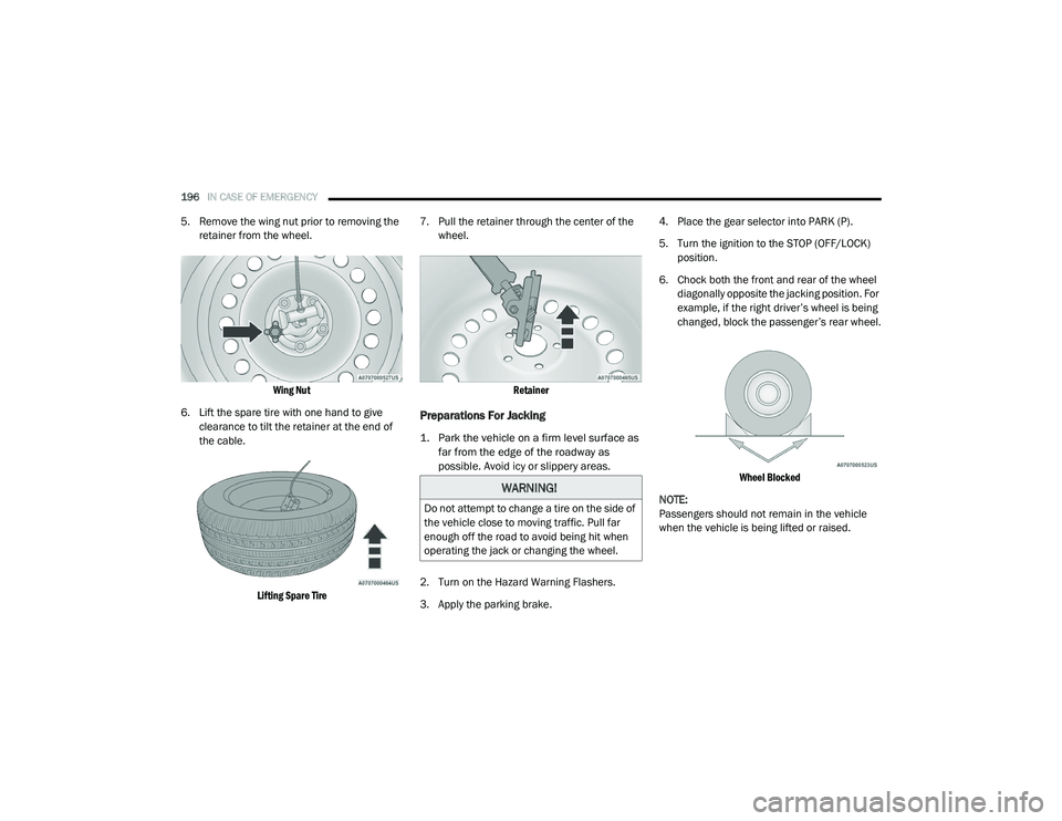
5. Remove the wing nut prior to removing the
retainer from the wheel.
Wing Nut
6. Lift the spare tire with one hand to give clearance to tilt the retainer at the end of
the cable.
Lifting Spare Tire
7. Pull the retainer through the center of the
wheel.
Retainer
Preparations For Jacking
1. Park the vehicle on a firm level surface as far from the edge of the roadway as
possible. Avoid icy or slippery areas.
2. Turn on the Hazard Warning Flashers.
3. Apply the parking brake. 4. Place the gear selector into PARK (P).
5. Turn the ignition to the STOP (OFF/LOCK)
position.
6. Chock both the front and rear of the wheel diagonally opposite the jacking position. For
example, if the right driver’s wheel is being
changed, block the passenger’s rear wheel.
Wheel Blocked
NOTE:
Passengers should not remain in the vehicle
when the vehicle is being lifted or raised.
WARNING!
Do not attempt to change a tire on the side of
the vehicle close to moving traffic. Pull far
enough off the road to avoid being hit when
operating the jack or changing the wheel.
21_VM_OM_EN_USC_t.book Page 196
Page 199 of 280

IN CASE OF EMERGENCY197
(Continued)
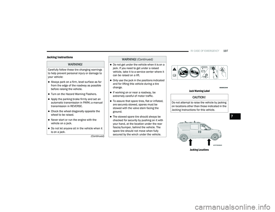
Jacking Instructions
Jack Warning Label Jacking Locations
WARNING!
Carefully follow these tire changing warnings
to help prevent personal injury or damage to
your vehicle:
Always park on a firm, level surface as far
from the edge of the roadway as possible
before raising the vehicle.
Turn on the Hazard Warning Flashers.
Apply the parking brake firmly and set an
automatic transmission in PARK; a manual
transmission in REVERSE.
Chock the wheel diagonally opposite the
wheel to be raised.
Never start or run the engine with the
vehicle on a jack.
Do not let anyone sit in the vehicle when it
is on a jack.
Do not get under the vehicle when it is on a
jack. If you need to get under a raised
vehicle, take it to a service center where it
can be raised on a lift.
Only use the jack in the positions indicated
and for lifting this vehicle during a tire
change.
If working on or near a roadway, be
extremely careful of motor traffic.
To assure that spare tires, flat or inflated,
are securely stowed, spares must be
stowed with the valve stem facing the
ground.
The stowed spare tire should always be
checked for security by pushing on it with
your hand, at the location under the rear
fascia/bumper, behind the vehicle. The
spare tire should not move when fully
secured by the winch under the vehicle.
WARNING! (Continued)
CAUTION!
Do not attempt to raise the vehicle by jacking
on locations other than those indicated in the
Jacking Instructions for this vehicle.
7
21_VM_OM_EN_USC_t.book Page 197
Page 208 of 280

206IN CASE OF EMERGENCY
See below steps to prepare for jump starting:
1. Apply the parking brake, shift the
automatic transmission into PARK (P) and
turn the ignition to STOP.
2. Turn off the heater, radio, and all electrical accessories.
3. If using another vehicle to jump-start the battery, park the vehicle within the jumper
cables reach, apply the parking brake and
make sure the ignition is OFF.
Jump Starting Procedure
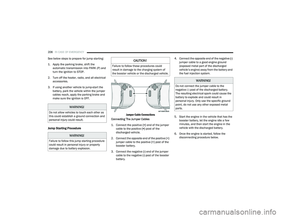
Jumper Cable Connections
Connecting The Jumper Cables
1. Connect the positive
(+) end of the jumper
cable to the positive (+)
post of the
discharged vehicle.
2. Connect the opposite end of the positive (+)
jumper cable to the positive (+) post of the
booster battery.
3. Connect the negative (-) end of the jumper
cable to the negative (-) post of the booster
battery. 4. Connect the opposite end of the negative
(-)
jumper cable to a good engine ground
(exposed metal part of the discharged
vehicle’s engine) away from the battery and
the fuel injection system.
5. Start the engine in the vehicle that has the booster battery, let the engine idle a few
minutes, and then start the engine in the
vehicle with the discharged battery.
6. Once the engine is started, follow the disconnecting procedure below.
WARNING!
Do not allow vehicles to touch each other as
this could establish a ground connection and
personal injury could result.
WARNING!
Failure to follow this jump starting procedure
could result in personal injury or property
damage due to battery explosion.
CAUTION!
Failure to follow these procedures could
result in damage to the charging system of
the booster vehicle or the discharged vehicle.
WARNING!
Do not connect the jumper cable to the
negative (-) post of the discharged battery.
The resulting electrical spark could cause the
battery to explode and could result in
personal injury. Only use the specific ground
point, do not use any other exposed metal
parts.
21_VM_OM_EN_USC_t.book Page 206
Page 209 of 280

IN CASE OF EMERGENCY207
Disconnecting The Jumper Cables
1. Disconnect the negative
(-)
end of the
jumper cable from the engine ground of
the vehicle with the discharged battery.
2. Disconnect the opposite end of the negative (-) jumper cable from the
negative (-) post of the booster battery.
3. Disconnect the positive (+) end of the
jumper cable from the positive (+) post of
the booster battery.
4. Disconnect the opposite end of the positive (+) jumper cable from the
positive (+) post of the vehicle with the
discharged battery.
If frequent jump starting is required to start your
vehicle you should have the battery and
charging system inspected at an authorized
dealer.
IF YOUR ENGINE OVERHEATS
If the vehicle is overheating, it will need to be
serviced by an authorized dealer.
In any of the following situations, you can
reduce the potential for overheating by taking
the appropriate action.
On the highways — slow down.
In city traffic — while stopped, place the trans -
mission in NEUTRAL (N), but do not increase
the engine idle speed while preventing
vehicle motion with the brakes. NOTE:
There are steps that you can take to slow down
an impending overheat condition:
If your Air Conditioner (A/C) is on, turn it off.
The A/C system adds heat to the engine
cooling system and turning the A/C off can
help remove this heat.
You can also turn the temperature control to
maximum heat, the mode control to floor and
the blower control to high. This allows the
heater core to act as a supplement to the
radiator and aids in removing heat from the
engine cooling system.
CAUTION!
Accessories plugged into the vehicle power
outlets draw power from the vehicle’s battery,
even when not in use (i.e., cellular devices,
etc.). Eventually, if plugged in long enough
without engine operation, the vehicle’s
battery will discharge sufficiently to degrade
battery life and/or prevent the engine from
starting.
WARNING!
You or others can be badly burned by hot
engine coolant (antifreeze) or steam from
your radiator. If you see or hear steam coming
from under the hood, do not open the hood
until the radiator has had time to cool. Never
try to open a cooling system pressure cap
when the radiator or coolant bottle is hot.7
21_VM_OM_EN_USC_t.book Page 207