2021 RAM PROMASTER CITY wheel
[x] Cancel search: wheelPage 44 of 280
42GETTING TO KNOW YOUR VEHICLE
(Continued)
To move the crossbars, loosen the
attachments, located at the upper edge of each
crossbar, approximately eight turns using the
anti-theft wrench provided with the Mopar
crossbars. Then, move the crossbar to the
desired position, keeping the crossbars parallel
to the rack frame. Once the crossbar is in the
desired position, re-tighten it with the wrench to
lock the crossbar into position.
NOTE:
To help control wind noise when the cross-
bars are not in use, place the front and rear
crossbars approximately 24 inches (61 cm)
apart. Optimal noise reduction can then be
achieved by adjusting the front crossbar
forward or aft using increments of 1 inch
(2.5 cm).
If the crossbar (or any metallic object) is
placed over the satellite radio antenna (if
equipped), you may experience interruption
of satellite radio reception. For improved
satellite radio reception, avoid placing the
rear crossbar over the satellite radio
antenna.
WARNING!
Cargo must be securely tied down before
driving your vehicle. Improperly secured loads
can fly off the vehicle, particularly at high
speeds, resulting in personal injury or
property damage. Follow the roof rack
cautions when carrying cargo on your roof
rack.
CAUTION!
To prevent damage to the roof of your
vehicle, DO NOT carry any loads on the roof
rack without the crossbars deployed. The
load should be secured and placed on top
of the crossbars, not directly on the roof. If
it is necessary to place the load on the roof,
place a blanket or other protective layer
between the load and the roof surface.
To avoid damage to the roof rack and
vehicle, do not exceed the maximum roof
rack load capacity of 150 lb (68 kg). Always
distribute heavy loads as evenly as possible
and secure the load appropriately.
Loads should always be secured to cross -
bars first, with tie down loops used as addi -
tional securing points if needed. Tie loops
are intended as supplementary tie down
points only. Do not use ratcheting mecha -
nisms with the tie loops. Check the straps
and thumb wheels frequently to be sure
that the load remains securely attached.
Long loads that extend over the windshield,
such as wood panels or surfboards, or
loads with large frontal area should be
secured to both the front and rear of the
vehicle.
Travel at reduced speeds and turn corners
carefully when carrying large or heavy loads
on the roof rack. Wind forces, due to
natural causes or nearby truck traffic, can
add sudden upward lift to a load. This is
especially true on large flat loads and may
result in damage to the cargo or your
vehicle.
CAUTION! (Continued)
21_VM_OM_EN_USC_t.book Page 42
Page 46 of 280
44GETTING TO KNOW YOUR INSTRUMENT PANEL
Instrument Cluster Descriptions
1. Speedometer
Indicates vehicle speed.
2. Fuel Gauge
The pointer shows the level of fuel in the
fuel tank when the ignition switch is in
the ON/RUN position.
The fuel pump arrow symbol points
to the side of the vehicle where the
fuel door is located.
3. Temperature Gauge
The temperature gauge shows engine
coolant temperature. Any reading within
the normal range indicates that the
engine cooling system is operating satis -
factorily.
The pointer will likely indicate a higher
temperature when driving in hot weather
or up mountain grades. It should not be
allowed to exceed the upper limits of the
normal operating range. 4. Tachometer
Indicates the engine speed in revolutions
per minute (RPM x 1000).
5. Instrument Cluster Display
When the appropriate conditions exist,
this display shows the instrument cluster
display messages Ú page 44.
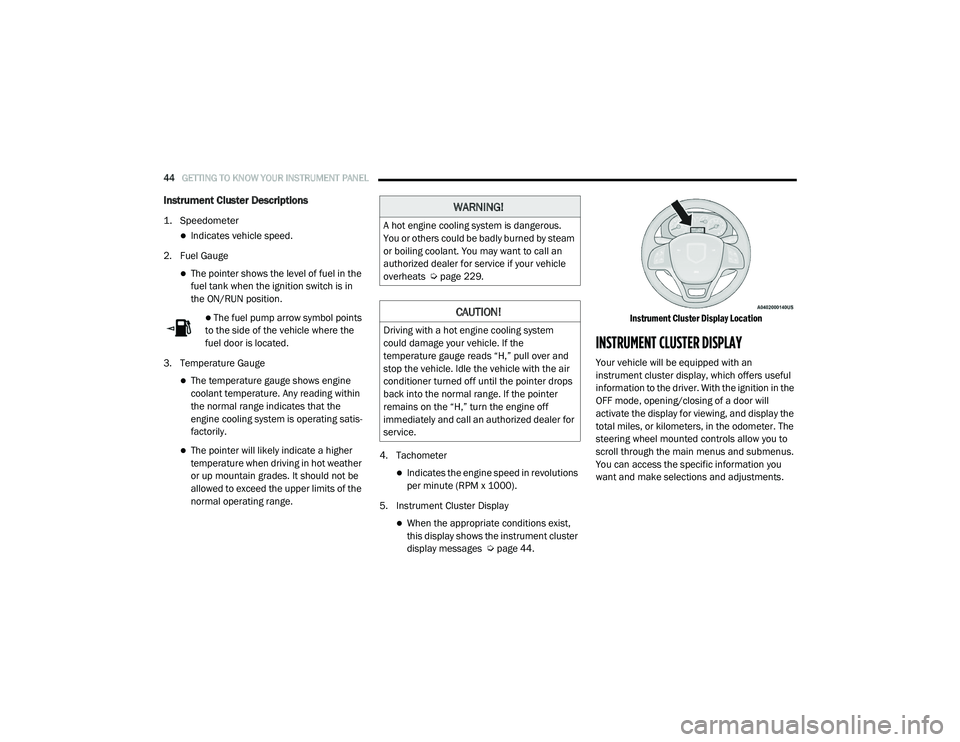
Instrument Cluster Display Location
INSTRUMENT CLUSTER DISPLAY
Your vehicle will be equipped with an
instrument cluster display, which offers useful
information to the driver. With the ignition in the
OFF mode, opening/closing of a door will
activate the display for viewing, and display the
total miles, or kilometers, in the odometer. The
steering wheel mounted controls allow you to
scroll through the main menus and submenus.
You can access the specific information you
want and make selections and adjustments.
WARNING!
A hot engine cooling system is dangerous.
You or others could be badly burned by steam
or boiling coolant. You may want to call an
authorized dealer for service if your vehicle
overheats Ú
page 229.
CAUTION!
Driving with a hot engine cooling system
could damage your vehicle. If the
temperature gauge reads “H,” pull over and
stop the vehicle. Idle the vehicle with the air
conditioner turned off until the pointer drops
back into the normal range. If the pointer
remains on the “H,” turn the engine off
immediately and call an authorized dealer for
service.
21_VM_OM_EN_USC_t.book Page 44
Page 47 of 280
GETTING TO KNOW YOUR INSTRUMENT PANEL45
Location And Controls
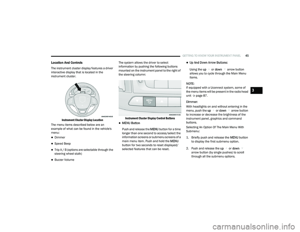
The instrument cluster display features a driver
interactive display that is located in the
instrument cluster.
Instrument Cluster Display Location
The menu items described below are an
example of what can be found in the vehicle's
menu:
Dimmer
Speed Beep
Trip A / B (options are selectable through the
steering wheel stalk)
Buzzer Volume The system allows the driver to select
information by pushing the following buttons
mounted on the instrument panel to the right of
the steering column:
Instrument Cluster Display Control Buttons
MENU Button
Push and release the MENU button for a time
longer than one second to access/select the
information screens or submenu screens of a
main menu item. Push and hold the MENU
button for two seconds to reset displayed/
selected features that can be reset.
Up And Down Arrow Buttons:
Using the up or down arrow button
allows you to cycle through the Main Menu
Items.
NOTE:
If equipped with a Uconnect system, some of
the menu items will be present in the radio head
unit Ú page 87.
Dimmer:
With headlights on and without entering in the
menu, push the up or down arrow button
to increase or decrease the brightness of the
instrument panel, graphics and command
buttons.
Selecting An Option Of The Main Menu With
Submenu:
1. Briefly push and release the
MENU
button
to display the first submenu option.
2. Push and release the up or down
arrow button (by single pushes) to scroll
through all the submenu options.
3
21_VM_OM_EN_USC_t.book Page 45
Page 55 of 280
GETTING TO KNOW YOUR INSTRUMENT PANEL53
Tire Pressure Monitoring System (TPMS)
Warning Light
The warning light switches on and a
message is displayed to indicate that
the tire pressure is lower than the
recommended value and/or that slow
pressure loss is occurring. In these cases,
optimal tire duration and fuel consumption may
not be guaranteed.
Should one or more tires be in the condition
mentioned above, the display will show the
indications corresponding to each tire.
Each tire, including the spare (if provided),
should be checked monthly when cold and
inflated to the inflation pressure recommended
by the vehicle manufacturer on the vehicle
placard or tire inflation pressure label. If your
vehicle has tires of a different size than the size indicated on the vehicle placard or tire inflation
pressure label, you should determine the
proper tire inflation pressure for those tires.
As an added safety feature, your vehicle has
been equipped with a TPMS that illuminates a
low tire pressure telltale when one or more of
your tires is significantly underinflated.
Accordingly, when the low tire pressure telltale
illuminates, you should stop and check your
tires as soon as possible, and inflate them to
the proper pressure. Driving on a significantly
underinflated tire causes the tire to overheat
and can lead to tire failure. Under-inflation also
reduces fuel efficiency and tire tread life, and
may affect the vehicle’s handling and stopping
ability.
Please note that the TPMS is not a substitute for
proper tire maintenance, and it is the driver’s
responsibility to maintain correct tire pressure,
even if under-inflation has not reached the level
to trigger illumination of the TPMS low tire
pressure telltale.
Your vehicle has also been equipped with a
TPMS malfunction indicator to indicate when
the system is not operating properly. The TPMS
malfunction indicator is combined with the low
tire pressure telltale. When the system detects
a malfunction, the telltale will flash for approximately one minute and then remain
continuously illuminated. This sequence will
continue upon subsequent vehicle start-ups as
long as the malfunction exists. When the
malfunction indicator is illuminated, the system
may not be able to detect or signal low tire
pressure as intended. TPMS malfunctions may
occur for a variety of reasons, including the
installation of replacement or alternate tires or
wheels on the vehicle that prevent the TPMS
from functioning properly. Always check the
TPMS malfunction telltale after replacing one or
more tires or wheels on your vehicle to ensure
that the replacement or alternate tires and
wheels allow the TPMS to continue to function
properly.
CAUTION!
Do not continue driving with one or more flat
tires as handling may be compromised. Stop
the vehicle, avoiding sharp braking and
steering. If a tire puncture occurs, repair
immediately using the dedicated tire repair
kit and contact an authorized dealer as soon
as possible.
3
21_VM_OM_EN_USC_t.book Page 53
Page 56 of 280

54GETTING TO KNOW YOUR INSTRUMENT PANEL
Vehicle Security Warning Light
This warning light will illuminate when
the vehicle security system has
detected an attempt to break into the
vehicle.
Engine Check/Malfunction Indicator Warning
Light (MIL)
The Engine Check/Malfunction
Indicator Light (MIL) is a part of an
Onboard Diagnostic System called
OBD II that monitors engine and
automatic transmission control systems. This
warning light will illuminate when the ignition is in
the ON/RUN position before engine start. After
placing the ignition to the ON/RUN position, if
there is a problem with the Sentry Key System,
the Vehicle Security Light will turn on. This
condition will result in the engine being shut off
after two seconds. If the bulb does not come on
when turning the ignition switch from OFF to ON/
RUN, have the condition checked promptly.
NOTE:
This warning light will illuminate when the
vehicle security system has detected an
attempt to break into the vehicle.
Certain conditions, such as a loose or missing
gas cap, poor quality fuel, etc., may illuminate the
light after engine start. The vehicle should be
serviced if the light stays on through several
typical driving styles. In most situations, the
vehicle will drive normally and will not require
towing. When the engine is running, the MIL may flash
to alert serious conditions that could lead to
immediate loss of power or severe catalytic
converter damage. The vehicle should be
serviced by an authorized dealer as soon as
possible if this occurs.
CAUTION!
The TPMS has been optimized for the original
equipment tires and wheels. TPMS pressures
and warning have been established for the
tire size equipped on your vehicle.
Undesirable system operation or sensor
damage may result when using replacement
equipment that is not of the same size, type,
and/or style. Aftermarket wheels can cause
sensor damage. Using aftermarket tire
sealants may cause the Tire Pressure
Monitoring System (TPMS) sensor to become
inoperable. After using an aftermarket tire
sealant it is recommended that you take your
vehicle to an authorized dealer to have your
sensor function checked.
WARNING!
A malfunctioning catalytic converter, as refer
-
enced above, can reach higher temperatures
than in normal operating conditions. This can
cause a fire if you drive slowly or park over
flammable substances such as dry plants,
wood, cardboard, etc. This could result in
death or serious injury to the driver, occu -
pants or others.
CAUTION!
Prolonged driving with the Malfunction
Indicator Light (MIL) on could cause damage
to the vehicle control system. It also could
affect fuel economy and driveability. If the
MIL is flashing, severe catalytic converter
damage and power loss will soon occur.
Immediate service is required.
21_VM_OM_EN_USC_t.book Page 54
Page 63 of 280
STARTING AND OPERATING61
(Continued)
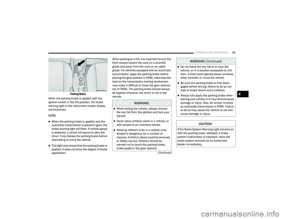
Parking Brake
When the parking brake is applied with the
ignition switch in the ON position, the brake
warning light in the instrument cluster display
will illuminate.
NOTE:
When the parking brake is applied and the
automatic transmission is placed in gear, the
brake warning light will flash. If vehicle speed
is detected, a chime will sound to alert the
driver. Fully release the parking brake before
attempting to move the vehicle.
This light only shows that the parking brake is
applied. It does not show the degree of brake
application. When parking on a hill, it is important to turn the
front wheels toward the curb on a downhill
grade and away from the curb on an uphill
grade. For vehicles equipped with an automatic
transmission, apply the parking brake before
placing the gear selector in PARK, otherwise the
load on the transmission locking mechanism
may make it difficult to move the gear selector
out of PARK. The parking brake should always
be applied whenever the driver is not in the
vehicle.
WARNING!
When exiting the vehicle, always remove
the key fob from the ignition and lock your
vehicle.
Never leave children alone in a vehicle, or
with access to an unlocked vehicle.
Allowing children to be in a vehicle unat
-
tended is dangerous for a number of
reasons. A child or others could be seriously
or fatally injured. Children should be
warned not to touch the parking brake,
brake pedal or the gear selector.
Do not leave the key fob in or near the
vehicle, or in a location accessible to chil -
dren. A child could operate power windows,
other controls, or move the vehicle.
Be sure the parking brake is fully disen -
gaged before driving; failure to do so can
lead to brake failure and a collision.
Always fully apply the parking brake when
leaving your vehicle or it may roll and cause
damage or injury. Also, be certain to leave
an automatic transmission in PARK. Failure
to do so may cause the vehicle to roll and
cause damage or injury.
CAUTION!
If the Brake System Warning Light remains on
with the parking brake released, a brake
system malfunction is indicated. Have the
brake system serviced by an authorized
dealer immediately.
WARNING! (Continued)
4
21_VM_OM_EN_USC_t.book Page 61
Page 66 of 280
![RAM PROMASTER CITY 2021 Owners Manual
64STARTING AND OPERATING
(Continued)
(Continued)
gear selector to the right (into the DRIVE [D]
position) for access to PARK, REVERSE, and
NEUTRAL.
Gear Selector
Gear Ranges
Do not press the ac RAM PROMASTER CITY 2021 Owners Manual
64STARTING AND OPERATING
(Continued)
(Continued)
gear selector to the right (into the DRIVE [D]
position) for access to PARK, REVERSE, and
NEUTRAL.
Gear Selector
Gear Ranges
Do not press the ac](/manual-img/34/59212/w960_59212-65.png)
64STARTING AND OPERATING
(Continued)
(Continued)
gear selector to the right (into the DRIVE [D]
position) for access to PARK, REVERSE, and
NEUTRAL.
Gear Selector
Gear Ranges
Do not press the accelerator pedal when
shifting out of PARK or NEUTRAL.
NOTE:
After selecting any gear range, wait a moment
to allow the selected gear to engage before
accelerating. This is especially important when
the engine is cold.
PARK (P)
The engine can be started in this range. Never
attempt to use PARK while the vehicle is in
motion. If necessary, apply the parking brake
prior to placing the vehicle in PARK.
When parking on a hill, apply the parking brake
before shifting the transmission to PARK,
otherwise the load on the transmission locking
mechanism may make it difficult to move the
gear selector out of PARK. As an added
precaution, turn the front wheels toward the
curb on a downhill grade and away from the
curb on an uphill grade.
When exiting the vehicle, always:
Apply the parking brake.
Shift the transmission into PARK.
Turn the engine off.
Remove the ignition key.
WARNING!
Never use the PARK position as a substi -
tute for the parking brake. Always apply the
parking brake fully when exiting the vehicle
to guard against vehicle movement and
possible injury or damage.
Your vehicle could move and injure you and
others if it is not in PARK. Check by trying to
move the gear selector out of PARK with the
brake pedal released. Make sure the trans -
mission is in PARK before exiting the vehicle.
It is dangerous to shift out of PARK or
NEUTRAL if the engine speed is higher than
idle speed. If your foot is not firmly pressing
the brake pedal, the vehicle could accel -
erate quickly forward or in reverse. You
could lose control of the vehicle and hit
someone or something. Only shift into gear
when the engine is idling normally and your
foot is firmly pressing the brake pedal.
Unintended movement of a vehicle could
injure those in or near the vehicle. As with
all vehicles, you should never exit a vehicle
while the engine is running. Before exiting a
vehicle always come to a complete stop,
then apply the parking brake, shift the
transmission into PARK, turn the engine off,
and remove the ignition key. Once the key is
removed, the transmission is locked in
PARK, securing the vehicle against
unwanted movement.
WARNING! (Continued)
21_VM_OM_EN_USC_t.book Page 64
Page 69 of 280
STARTING AND OPERATING67
Torque Converter Clutch
A feature designed to improve fuel economy
has been included in the automatic
transmission on your vehicle. A clutch within the
torque converter engages automatically at
calibrated speeds. This may result in a slightly
different feeling or response during normal
operation in the upper gears. When the vehicle
speed drops or during some accelerations, the
clutch automatically disengages.
NOTE:
The torque converter clutch will not engage until
the transmission fluid is warm [usually after 1 to
3 miles (2 to 5 km) of driving]. Because the
engine speed is higher when the torque
converter clutch is not engaged, it may seem as
if the transmission is not shifting properly when
cold. This is normal. The torque converter clutch
will function normally once the transmission is
sufficiently warm.
Electronic Range Select (ERS) Operation
The Electronic Range Select (ERS) shift control
allows the driver to limit the highest available
gear. For example, if you set the transmission
gear limit to fifth gear, the transmission will not
shift above fifth gear, but will shift through the
lower gears normally. You can switch between DRIVE and ERS mode
at any vehicle speed. When the gear selector is
in the DRIVE position, the transmission will
operate automatically, shifting between all
available gears.
Moving the gear selector to the ERS position
(beside DRIVE) will activate ERS mode, display
the current gear in the instrument cluster, and
set that gear as the top available gear. Once in
ERS mode, moving the gear selector forward (-)
or rearward (+) will change the top available
gear, which will be displayed in the instrument
cluster.
To exit ERS mode, simply return the gear
selector to the DRIVE position.
NOTE:
To select the proper gear position for maximum
deceleration (engine braking), move the gear
selector into the ERS position, then simply press
and hold it forward (-). The transmission will
shift to the range from which the vehicle can
best be slowed down.
POWER STEERING
The standard power steering system will give
you good vehicle response and increased ease
of maneuverability in tight spaces. The system
will provide mechanical steering capability if
power assist is lost.
If for some reason the power assist is
interrupted, it will still be possible to steer your
vehicle. Under these conditions, you will
observe a substantial increase in steering
effort, especially at very low vehicle speeds and
during parking maneuvers.
WARNING!
Do not downshift for additional engine
braking on a slippery surface. The drive
wheels could lose their grip and the vehicle
could skid, causing a collision or personal
injury.
4
21_VM_OM_EN_USC_t.book Page 67