2021 RAM PROMASTER CITY trailer
[x] Cancel search: trailerPage 82 of 280
80STARTING AND OPERATING
(Continued)
Towing Requirements — Tires
Do not attempt to tow a trailer while using a
compact spare tire.
Do not drive more than 50 mph (80 km/h) when towing while using a full size spare tire.
Proper tire inflation pressures are essential
to the safe and satisfactory operation of your
vehicle.
Check the trailer tires for proper tire inflation
pressures before trailer usage.
Check for signs of tire wear or visible tire
damage before towing a trailer.
When replacing tires with a higher load
carrying capacity they will not increase the
vehicle's GVWR and GAWR limits.
For further information Ú page 234.
WARNING!
Make certain that the load is secured in the
trailer and will not shift during travel. When
trailering cargo that is not fully secured,
dynamic load shifts can occur that may be
difficult for the driver to control. You could
lose control of your vehicle and have a colli -
sion.
When hauling cargo or towing a trailer, do
not overload your vehicle or trailer. Over -
loading can cause a loss of control, poor
performance or damage to brakes, axle,
engine, transmission, steering, suspension,
chassis structure or tires.
Safety chains must always be used
between your vehicle and trailer. Always
connect the chains to the hook retainers of
the vehicle hitch. Cross the chains under
the trailer tongue and allow enough slack
for turning corners.
Vehicles with trailers should not be parked
on a grade. When parking, apply the
parking brake on the tow vehicle. Put the
tow vehicle transmission in PARK. For
four-wheel drive vehicles, make sure the
transfer case is not in NEUTRAL. Always,
block or "chock" the trailer wheels.
GCWR must not be exceeded.
Total weight must be distributed between
the tow vehicle and the trailer such that the
following four ratings are not exceeded :
GVWR
GTW
GAWR
Tongue weight rating for the trailer
hitch utilized.
WARNING! (Continued)
21_VM_OM_EN_USC_t.book Page 80
Page 83 of 280
STARTING AND OPERATING81
Towing Requirements — Trailer Brakes
Do not interconnect the hydraulic brake
system or vacuum system of your vehicle
with that of the trailer. This could cause inad -
equate braking and possible personal injury.
An electronically actuated trailer brake
controller is required when towing a trailer
with electronically actuated brakes. When
towing a trailer equipped with a hydraulic
surge actuated brake system, an electronic
brake controller is not required.
Trailer brakes are recommended for trailers
over 1,000 lbs (453 kg) and required for
trailers in excess of 2,000 lbs (907 kg).
Towing Requirements — Trailer Lights And
Wiring
Whenever you pull a trailer, regardless of the
trailer size, stoplights and turn signals on the
trailer are required for motoring safety.
The Trailer Tow Package may include a four- and
seven-pin wiring harness. Use a factory
approved trailer harness and connector.
NOTE:
Do not cut or splice wiring into the vehicle’s
wiring harness.
The electrical connections are all complete to
the vehicle but you must mate the harness to a
trailer connector. Refer to the following
illustrations. NOTE:
Disconnect trailer wiring connector from the
vehicle before launching a boat (or any other
device plugged into vehicle’s electrical
connect) into water.
Be sure to reconnect once clear from water
area.
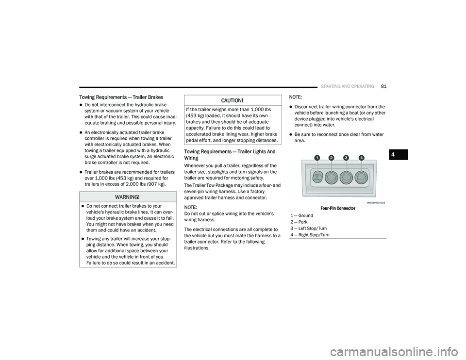
Four-Pin Connector
WARNING!
Do not connect trailer brakes to your
vehicle's hydraulic brake lines. It can over -
load your brake system and cause it to fail.
You might not have brakes when you need
them and could have an accident.
Towing any trailer will increase your stop -
ping distance. When towing, you should
allow for additional space between your
vehicle and the vehicle in front of you.
Failure to do so could result in an accident.
CAUTION!
If the trailer weighs more than 1,000 lbs
(453 kg) loaded, it should have its own
brakes and they should be of adequate
capacity. Failure to do this could lead to
accelerated brake lining wear, higher brake
pedal effort, and longer stopping distances.
1 — Ground
2 — Park
3 — Left Stop/Turn
4 — Right Stop/Turn
4
21_VM_OM_EN_USC_t.book Page 81
Page 84 of 280
82STARTING AND OPERATING
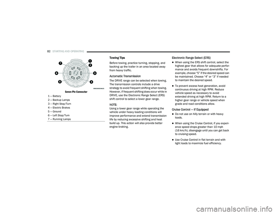
Seven-Pin Connector
Towing Tips
Before towing, practice turning, stopping, and
backing up the trailer in an area located away
from heavy traffic.
Automatic Transmission
The DRIVE range can be selected when towing.
The transmission controls include a drive
strategy to avoid frequent shifting when towing.
However, if frequent shifting does occur while in
DRIVE, use the Electronic Range Select (ERS)
shift control to select a lower gear range.
NOTE:
Using a lower gear range while operating the
vehicle under heavy loading conditions will
improve performance and extend transmission
life by reducing excessive shifting and heat
build up. This action will also provide better
engine braking.
Electronic Range Select (ERS)
When using the ERS shift control, select the
highest gear that allows for adequate perfor -
mance and avoids frequent downshifts. For
example, choose “5” if the desired speed can
be maintained. Choose “4” or “3” if needed
to maintain the desired speed.
To prevent excess heat generation, avoid
continuous driving at high RPM. Reduce
vehicle speed as necessary to avoid
extended driving at high RPM. Return to a
higher gear range or vehicle speed when
grade and road conditions allow.
Cruise Control — If Equipped
Do not use on hilly terrain or with heavy
loads.
When using the Cruise Control, if you experi -
ence speed drops greater than 10 mph
(16 km/h), disengage until you can get back
to cruising speed.
Use Cruise Control in flat terrain and with
light loads to maximize fuel efficiency.
1 — Battery
2 — Backup Lamps
3 — Right Stop/Turn
4 — Electric Brakes
5 — Ground
6 — Left Stop/Turn
7 — Running Lamps
21_VM_OM_EN_USC_t.book Page 82
Page 85 of 280
STARTING AND OPERATING83
RECREATIONAL TOWING (BEHIND MOTORHOME)
Towing This Vehicle Behind Another Vehicle
NOTE:
When towing your vehicle, always follow appli -
cable state and provincial laws. Contact state
and provincial Highway Safety offices for addi -
tional details.
Recreational Towing — Automatic
Transmission
Recreational towing is allowed ONLY if the front
wheels are OFF the ground. This may be
accomplished using a tow dolly or vehicle
trailer. If using a tow dolly, follow this procedure:
1. Properly secure the dolly to the tow vehicle,
following the dolly manufacturer's
instructions.
2. Drive the front wheels onto the tow dolly.
3. Firmly apply the parking brake. Place the transmission in PARK.
4. Properly secure the front wheels to the dolly, following the dolly manufacturer's
instructions.
5. Release the parking brake.
Towing Condition Wheels OFF The Ground Automatic Transmission
Flat Tow NONENOT ALLOWED
Dolly Tow Front
OK
Rear NOT ALLOWED
On Trailer ALLOK
CAUTION!
DO NOT flat tow this vehicle. Damage to the
drivetrain will result. If this vehicle requires
towing, make sure the drive wheels are OFF
the ground.
Towing this vehicle in violation of the above
requirements can cause severe transmis-
sion damage. Damage from improper
towing is not covered under the New
Vehicle Limited Warranty.
4
21_VM_OM_EN_USC_t.book Page 83
Page 148 of 280

146SAFETY
Electronic Brake Control (EBC) System
Your vehicle is equipped with an advanced
Electronic Brake Control (EBC) system that
includes the Brake Assist System (BAS),
Traction Control System (TCS), Hill Start Assist
(HSA), Electronic Stability Control (ESC),
Electronic Roll Mitigation (ERM) and Trailer
Sway Control (TSC). All systems work together to
enhance vehicle stability and control in various
driving conditions and are commonly referred to
as ESC.
Brake Assist System (BAS)
BAS is designed to optimize the vehicle’s
braking capability during emergency braking
maneuvers. The system detects an emergency
braking situation by sensing the rate and
amount of brake application and then applies
optimum pressure to the brakes. This can help
reduce braking distances. The BAS
complements the Anti-Lock Brake System
(ABS). Applying the brakes very quickly results
in the best BAS assistance. To receive the
benefit of the system, you must apply continuous braking pressure during the
stopping sequence (do not “pump” the brakes).
Do not reduce brake pedal pressure unless
braking is no longer desired. Once the brake
pedal is released, the BAS is deactivated.
Electronic Stability Control (ESC)
ESC enhances directional control and stability
of the vehicle under various driving conditions.
ESC corrects for over/under steering of the
vehicle by applying the brake of the appropriate
wheel to counteract the above conditions.
Engine power may also be reduced to help the
vehicle maintain the desired path.
Oversteer - when the vehicle is turning more
than appropriate for the steering wheel posi
-
tion.
Understeer - when the vehicle is turning less
than appropriate for the steering wheel posi -
tion.
ESC uses sensors in the vehicle to determine
the vehicle path intended by the driver and
compares it to the actual path of the vehicle.
When the actual path does not match the
intended path, ESC applies the brake of the
appropriate wheel to assist in counteracting the
oversteer or understeer condition.
WARNING!
The Brake Assist System (BAS) cannot
prevent the natural laws of physics from
acting on the vehicle, nor can it increase the
traction afforded by prevailing road
conditions. BAS cannot prevent collisions,
including those resulting from excessive
speed in turns, driving on very slippery
surfaces, or hydroplaning. The capabilities of
a BAS-equipped vehicle must never be
exploited in a reckless or dangerous manner,
which could jeopardize the user's safety or
the safety of others.
21_VM_OM_EN_USC_t.book Page 146
Page 151 of 280

SAFETY149
HSA will work in REVERSE and all forward gears
when the activation criteria have been met. The
system will not activate if the vehicle is placed
in NEUTRAL or PARK.
Traction Control System (TCS)
TCS monitors the amount of wheel spin of each
of the driven wheels. If wheel spin is detected,
brake pressure is applied to the slipping
wheel(s) and engine power is reduced to
provide enhanced acceleration and stability. A
feature of the TCS system, Brake Limited
Differential (BLD), functions similarly to a
limited slip differential and controls the wheel
spin across a driven axle. If one wheel on a
driven axle is spinning faster than the other, the
system will apply the brake of the spinning wheel. This will allow more engine torque to be
applied to the wheel that is not spinning. This
feature remains active even if TCS and ESC are
in the “Partial Off” mode Ú
page 146.
Trailer Sway Control (TSC) — If Equipped
TSC uses sensors in the vehicle to recognize an
excessively swaying trailer and will take the
appropriate actions to attempt to stop the sway.
The system may reduce engine power and apply
the brake of the appropriate wheel(s) to
counteract the sway of the trailer.
NOTE:
TSC cannot stop all trailers from swaying.
Always use caution when towing a trailer and
follow the trailer tongue weight recommenda -
tions Ú page 77.
When TSC is functioning, the ESC Activation/
Malfunction Indicator Light will flash, the engine
power may be reduced and you may feel the
brakes being applied to individual wheels to
attempt to stop the trailer from swaying. TSC is
disabled when the ESC system is in the “Partial
Off” mode.
AUXILIARY DRIVING SYSTEMS
Tire Pressure Monitoring System (TPMS)
The Tire Pressure Monitoring System (TPMS)
will warn the driver of a low tire pressure based
on the vehicle recommended cold placard
pressure.
The tire pressure will vary with temperature by
about 1 psi (7 kPa) for every 12°F (6.5°C). This
means that when the outside temperature
decreases, the tire pressure will decrease. Tire
pressure should always be set based on cold
inflation tire pressure. This is defined as the tire
pressure after the vehicle has not been driven
for at least three hours, or driven less than
1 mile (1.6 km) after a three hour period. The
cold tire inflation pressure must not exceed the
maximum inflation pressure molded into the
WARNING!
There may be situations on minor hills with a
loaded vehicle, or while pulling a trailer, when
the system will not activate and slight rolling
may occur. This could cause a collision with
another vehicle or object. Always remember
the driver is responsible for braking the
vehicle.
WARNING!
If TSC activates while driving, slow the vehicle
down, stop at the nearest safe location, and
adjust the trailer load to eliminate trailer
sway.
6
21_VM_OM_EN_USC_t.book Page 149
Page 219 of 280

217
SERVICING AND MAINTENANCE
SCHEDULED SERVICING
Your vehicle is equipped with an automatic oil
change indicator system. The oil change
indicator system will remind you that it is time to
take your vehicle in for scheduled maintenance.
Based on engine operation conditions, the oil
change indicator message will illuminate. This
means that service is required for your vehicle.
Operating conditions such as frequent
short-trips, trailer tow, extended engine idle
time, extremely hot or cold ambient
temperatures will influence when the “Oil
Change Required” message is displayed.
Severe Operating Conditions can cause the
change oil message to illuminate as early as
3,500 miles (5,600 km) since last reset. Have
your vehicle serviced as soon as possible,
within the next 500 miles (805 km).
An authorized dealer will reset the oil change
indicator message after completing the
scheduled oil change. If a scheduled oil change
is performed by someone other than an
authorized dealer, to reset the message
Úpage 46. NOTE:
Under no circumstances should oil change
intervals exceed 10,000 miles (16,000 km),
350 hours of engine run time or 12 months,
whichever comes first. The 350 hours of engine
run or idle time is generally only a concern for
fleet customers.
Severe Duty All Models
Vehicles that are operated in a dusty and
off-road environment, or predominately at idle
or very low engine RPM are known as Severe
Duty vehicles. It is recommended that you
change Engine Oil at 4,000 miles (6,500 km) or
350 hours of engine run time.
Once A Month Or Before A Long Trip:
Check engine oil level.
Check windshield washer fluid level.
Check tire pressure and look for unusual
wear or damage. Rotate tires at the first sign
of irregular wear, even if it occurs before the
oil indicator system turns on.
Check the fluid levels of the coolant reservoir
and brake master cylinder, fill as needed.
Check function of all interior and exterior
lights.
Maintenance Plan
Refer to the maintenance schedule for the
required maintenance intervals. More frequent
maintenance may be needed in severe
conditions, such as dusty areas and very short
trip driving. In some extreme conditions,
additional maintenance not specified in the
maintenance schedule may be required.
8
21_VM_OM_EN_USC_t.book Page 217
Page 242 of 280
240SERVICING AND MAINTENANCE
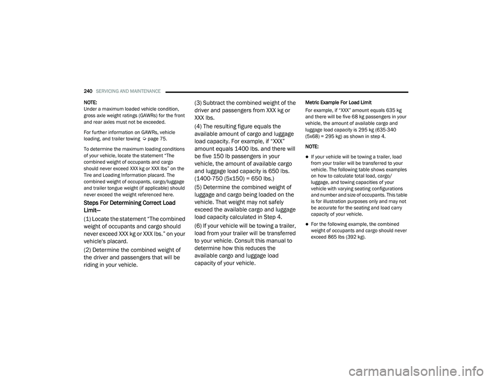
NOTE:
Under a maximum loaded vehicle condition,
gross axle weight ratings (GAWRs) for the front
and rear axles must not be exceeded.
For further information on GAWRs, vehicle
loading, and trailer towing Úpage 75.
To determine the maximum loading conditions
of your vehicle, locate the statement “The
combined weight of occupants and cargo
should never exceed XXX kg or XXX lbs” on the
Tire and Loading Information placard. The
combined weight of occupants, cargo/luggage
and trailer tongue weight (if applicable) should
never exceed the weight referenced here.
Steps For Determining Correct Load
Limit—
(1) Locate the statement “The combined
weight of occupants and cargo should
never exceed XXX kg or XXX lbs.” on your
vehicle's placard.
(2) Determine the combined weight of
the driver and passengers that will be
riding in your vehicle. (3) Subtract the combined weight of the
driver and passengers from XXX kg or
XXX lbs.
(4) The resulting figure equals the
available amount of cargo and luggage
load capacity. For example, if “XXX”
amount equals 1400 lbs. and there will
be five 150 lb passengers in your
vehicle, the amount of available cargo
and luggage load capacity is 650 lbs.
(1400-750 (5x150) = 650 lbs.)
(5) Determine the combined weight of
luggage and cargo being loaded on the
vehicle. That weight may not safely
exceed the available cargo and luggage
load capacity calculated in Step 4.
(6) If your vehicle will be towing a trailer,
load from your trailer will be transferred
to your vehicle. Consult this manual to
determine how this reduces the
available cargo and luggage load
capacity of your vehicle.
Metric Example For Load Limit
For example, if “XXX” amount equals 635 kg
and there will be five 68 kg passengers in your
vehicle, the amount of available cargo and
luggage load capacity is 295 kg (635-340
(5x68) = 295 kg) as shown in step 4.
NOTE:
If your vehicle will be towing a trailer, load
from your trailer will be transferred to your
vehicle. The following table shows examples
on how to calculate total load, cargo/
luggage, and towing capacities of your
vehicle with varying seating configurations
and number and size of occupants. This table
is for illustration purposes only and may not
be accurate for the seating and load carry
capacity of your vehicle.
For the following example, the combined
weight of occupants and cargo should never
exceed 865 lbs (392 kg).
21_VM_OM_EN_USC_t.book Page 240