2021 PEUGEOT BOXER wheel
[x] Cancel search: wheelPage 85 of 212
83
Driving
6– These traffic signs are then displayed in the
instrument panel.
The system can display two traffic signs (speed
limit and no overtaking/end of no overtaking)
in parallel in the two dedicated zones of the
instrument panel.
If an additional traffic sign is detected, such as
one for a reduced speed limit when the road is
wet, this is displayed in an empty window below
the corresponding sign.
Additional traffic signs are filtered as follows:
–
Signs related to snow or ice are displayed only
if the exterior temperature is below 3°C.
–
Signs related to snow
, rain or fog are
displayed only if the wipers are on and the
exterior temperature is below 3°C.
–
Signs related to heavy goods vehicles are only
displayed if they apply to vehicles weighing less
than 4 tonnes.
–
Signs related to farm vehicles are not
displayed.
Signs such as no overtaking are cleared from
the instrument panel after approximately 40
seconds.
Activation/Deactivation
This function can be set using the MODE button: in the “Traffic Sign” menu, select
“ON” or “OFF”.
For more information on Vehicle
configuration (MODE) , refer to the
corresponding section.
Operating limits
The system does not take account of reduced
speed limits, especially those imposed in the
following cases:
–
Poor weather (rain, snow).
–
Atmospheric pollution.
–
T
owing.
–
Driving with a space-saver type spare wheel
or snow chains fitted.
–
Driving with a non-standard suspension kit.
–
T
yre repaired using the temporary puncture
repair kit.
–
Y
oung drivers.
The system may not display the speed limit if it
does not detect a speed limit sign within a preset
period and in the following situations:
–
Road signs that are obstructed, non-standard,
damaged or bent.
–
Obsolete or incorrect maps.
–
Road incline causing the sign to be out of the
camera field of vision (on a slope, for example).
–
Change in the vehicle load that causes the
camera to tilt significantly (system operation may
temporarily be suspended to enable camera
self-calibration).
Speed limiter
For more information, refer to the
General recommendations on the use
of driving and manoeuvring aids .
System which prevents the vehicle
from exceeding the speed
programmed by the driver.
The speed is selected when the vehicle is
stationary with the engine running or while
driving with at least 2
nd gear engaged.
The minimum speed to be programmed is 19
mph (30 km/h).
Fully depressing the accelerator pedal allows
you to exceed the programmed speed. To
resume use of the speed limiter, gradually
release the pressure on the accelerator pedal
and return below the programmed speed.
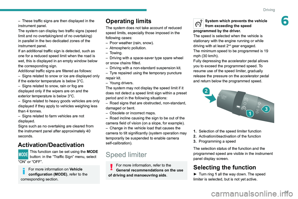
1. Selection of the speed limiter function
2. Activation/deactivation of the function
3. Programming a speed
The selection status of the function and the
programmed speed are visible in the instrument
panel display screen.
Selecting the function
► Turn ring 1 all the way down. The speed
limiter is selected, but is not yet active.
Page 87 of 212
85
Driving
6Cruise control - Specific
recommendations
The cruise control function does not guarantee compliance with the maximum
authorised speed and the safety distance
between vehicles, the driver remains
responsible for their driving.
In the interest of public safety, only use cruise
control if the traffic conditions enable vehicles
to drive at a steady speed and maintain an
adequate safety distance.
Remain vigilant while cruise control is
activated. If you press and hold one of the
speed setting modification buttons, your
vehicle may change speed very abruptly.
When descending a steep hill , the cruise
control system cannot prevent the vehicle
from exceeding the set speed. Brake if
necessary to control the vehicle speed.
On steep climbs or when towing, the set
speed may not be reached or maintained.
Exceeding the programmed speed
setting
You can temporarily exceed the speed
setting by pressing the accelerator pedal (the
programmed speed flashes).
To return to the speed setting, release the
accelerator pedal (when the set speed is
reached again, the displayed speed stops
flashing).
Operating limits
Never use the system in the following
situations:
–
In an urban area with the risk of
pedestrians crossing the road.
–
In heavy traffic.
–
On winding or steep roads.
–
On slippery or flooded roads.
–
In poor weather conditions.
–
In the event of restricted visibility for the
driver
.
–
Driving on a speed circuit.
–
Driving on a rolling road.
–
When using a ‘space-saver
’ type spare
wheel.
–
When using snow chains, non-slip covers
or studded tyres.
Cruise control
For more information, refer to the
General recommendations on the use
of driving and manoeuvring aids and the
Cruise control - particular
recommendations.
System which automatically maintains the
speed of the vehicle at the cruise setting
programmed by the driver, without using the
accelerator pedal. To be programmed or activated, the speed of the
vehicle must be above 19 mph (30 km/h), with at
least 2
nd gear engaged.
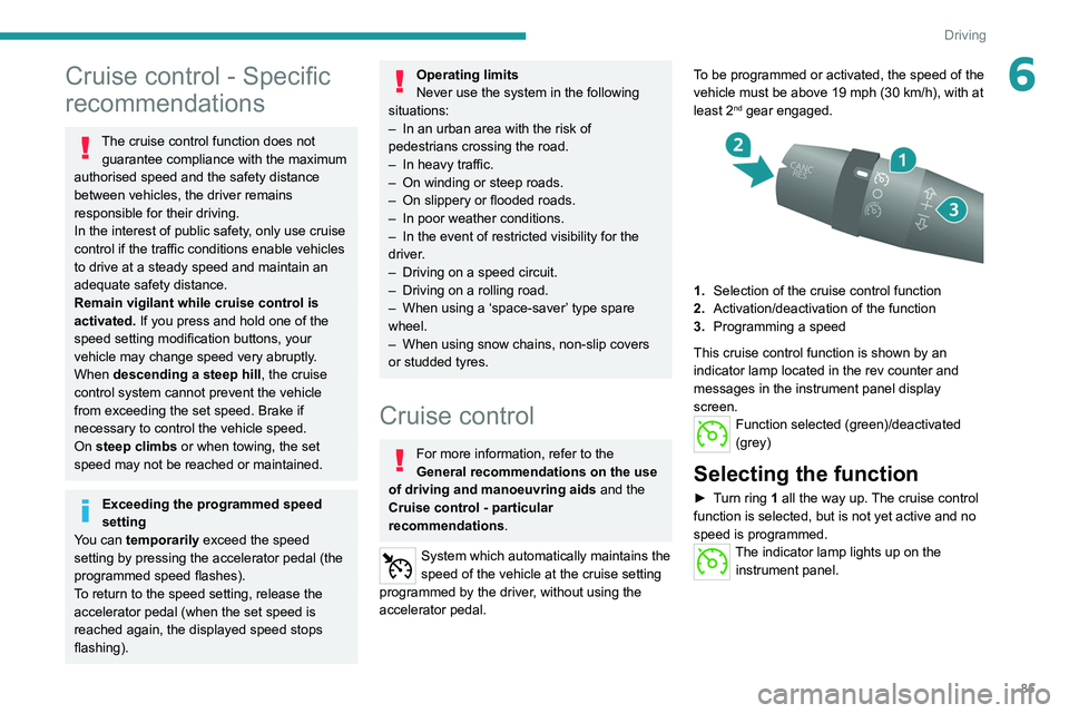
1.
Selection of the cruise control function
2. Activation/deactivation of the function
3. Programming a speed
This cruise control function is shown by an
indicator lamp located in the rev counter and
messages in the instrument panel display
screen.
Function selected (green)/deactivated
(grey)
Selecting the function
► Turn ring 1 all the way up. The cruise control
function is selected, but is not yet active and no
speed is programmed.
The indicator lamp lights up on the instrument panel.
Page 93 of 212
91
Driving
6This function can be set using the MODE button; in the "Active Safety Brake" menu,
select "ON" or "OFF".
For more information on Vehicle
configuration (MODE) , refer to the
corresponding section.
Deactivation of the system is signalled by
the illumination of this warning lamp,
accompanied by the display of a message.
Operating conditions and
limits
Vehicle moving forward.
ESC system operational.
DSC/ASR systems activated.
Seat belts fastened for all passengers.
Stabilised speed on roads with few bends.
In the following cases, deactivating the system
via the vehicle's configuration menu is advised:
–
T
owing a trailer.
–
Carrying long objects on roof bars or roof rack.
–
V
ehicle with snow chains fitted.
–
Before using an automatic car wash, with the
engine running.
–
When changing
a wheel, working near a wheel
or inside the engine compartment.
–
Before placing the vehicle on a rolling road in
a workshop.
–
T
owed vehicle, engine running.
–
Following
an impact to the windscreen close to
the detection camera.
The system is automatically deactivated when a fault with the brake pedal switch
or at least two brake lamps is detected.
It can be dangerous to drive if the brake
lamps are not in perfect working order.
The driver must not overload the vehicle (keep within the GVW limit and load
height limits for roof bars).
Following an impact, the system is
automatically deactivated.
Have it checked by a PEUGEOT dealer or a
qualified workshop.
It is possible that warnings are not given,
are given too late or seem unjustified.
The driver must always stay in control of their
vehicle and be prepared to react at any time
to avoid an accident.
Cases of non-detection by the system:
–
Pedestrians, cyclists, animals, objects on the
road.
–
V
ehicles crossing your lane.
–
V
ehicles driving in the opposite direction.
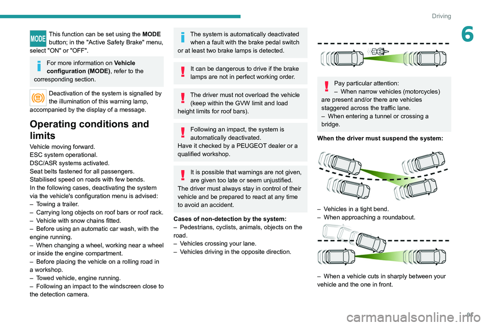
Pay particular attention:
– When narrow vehicles (motorcycles)
are present and/or there are vehicles
staggered across the traffic lane.
–
When entering a tunnel or crossing a
bridge.
When the driver must suspend the system:
– Vehicles in a tight bend.
– When approaching a roundabout.
– When a vehicle cuts in sharply between your
vehicle and the one in front.
Page 95 of 212

93
Driving
6This warning lamp flashes (for approximately 10 seconds) as soon as
the function applies the vehicle’s brakes.
With a manual gearbox, in the event of automatic
emergency braking bringing the vehicle to a
complete stop, the engine may stall.
The driver can maintain control of the vehicle at any time by firmly turning the
steering wheel and/or firmly depressing the
accelerator pedal.
The brake pedal may vibrate slightly while the function is operating.
If the vehicle comes to a complete stop,
automatic braking is maintained for 1 to 2
seconds.
Malfunction
In the event of a system malfunction, this
warning lamp comes on on the instrument
panel, accompanied by an onscreen message
and an audible signal.
Contact a PEUGEOT dealer or a qualified
workshop to have the system checked.
If these warning lamps come on
after the engine has been switched
off and then restarted, contact a PEUGEOT
dealer or a qualified workshop to have the
system checked.
Audible rear parking sensors
For more information, refer to the
General recommendations on the use
of driving and manoeuvring aids .
If fitted to your vehicle, the system consists of 4
proximity sensors installed in the rear bumper.
They detect any obstacle, e.g. person, vehicle,
tree, barrier, which is behind the vehicle while
manoeuvring.
Certain types of obstacle detected at the
beginning of the manoeuvre will no longer be
detected at the end of manoeuvre if they are
located in the blind spots between and under the
sensors. Examples: stake, roadworks cone or
pavement post.
The rear parking sensors may be associated
with the reversing camera.
Switching on
► Engage reverse gear with the gear lever .
The proximity information is indicated by an
audible signal which becomes more rapid as the
vehicle approaches the obstacle.
When the distance between the rear of
the vehicle and the obstacle is less than
approximately 30 centimetres, the audible signal
becomes continuous.
Switching off
► Disengage reverse gear and shift to neutral.
Malfunction
In the event of a malfunction, this warning
lamp lights up on the instrument panel.
Consult a PEUGEOT dealer or a qualified
workshop.
Page 105 of 212
103
Practical information
7
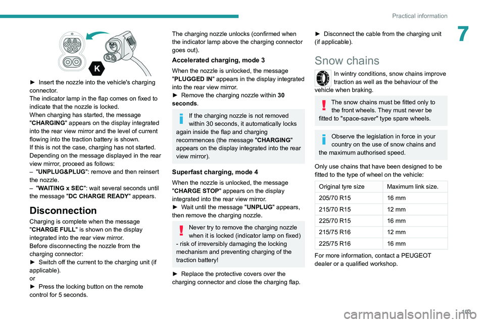
► Insert the nozzle into the vehicle's charging
connector .
The indicator lamp in the flap comes on fixed to
indicate that the nozzle is locked.
When charging has started, the message
"CHARGING" appears on the display integrated
into the rear view mirror and the level of current
flowing into the traction battery is shown.
If this is not the case, charging has not started.
Depending on the message displayed in the rear
view mirror, proceed as follows:
–
"UNPLUG&PLUG": remove and then reinsert
the nozzle.
–
"WAITING x SEC": wait several seconds until
the message "DC CHARGE READY " appears.
Disconnection
Charging is complete when the message
"CHARGE FULL" is shown on the display
integrated into the rear view mirror.
Before disconnecting the nozzle from the
charging connector:
►
Switch off the current to the charging unit (if
applicable).
or
►
Press the locking button on the remote
control for 5 seconds.
The charging nozzle unlocks (confirmed when
the indicator lamp above the charging connector
goes out).
Accelerated charging, mode 3
When the nozzle is unlocked, the message
"PLUGGED IN" appears in the display integrated
into the rear view mirror.
►
Remove the charging nozzle within 30
seconds
.
If the charging nozzle is not removed
within 30 seconds, it automatically locks
again inside the flap and charging
recommences (the message " CHARGING"
appears on the display integrated into the rear
view mirror).
Superfast charging, mode 4
When the nozzle is unlocked, the message
"CHARGE STOP" appears on the display
integrated into the rear view mirror.
►
W
ait until the message "UNPLUG" appears,
then remove the charging nozzle.
Never try to remove the charging nozzle
when it is locked (indicator lamp on fixed)
- risk of irreversibly damaging the locking
mechanism and preventing charging of the
traction battery!
►
Replace the protective covers over the
charging connector and close the charging flap.
► Disconnect the cable from the charging unit
(if applicable).
Snow chains
In wintry conditions, snow chains improve
traction as well as the behaviour of the
vehicle when braking.
The snow chains must be fitted only to the front wheels. They must never be
fitted to "space-saver" type spare wheels.
Observe the legislation in force in your
country on the use of snow chains and
the maximum authorised speed.
Only use chains that have been designed to be
fitted to the type of wheel on the vehicle:
Original tyre size Maximum link size.
205/70 R15 16 mm
215/70 R15 12 mm
225/70 R15 16 mm
215/75 R16 12 mm
225/75 R16 16 mm
For more information, contact a PEUGEOT
dealer or a qualified workshop.
Page 106 of 212

104
Practical information
Installation tips
► To fit the snow chains during a journey, stop
the vehicle on a flat surface at the side of the
road.
►
Apply the parking brake and position any
wheel chocks under the wheels to prevent
movement of the vehicle.
►
Fit the snow chains following the instructions
provided by the manufacturer
.
►
Move off gently and drive for a few moments,
without exceeding 31
mph (50 km/h).
►
Stop the vehicle and check that the snow
chains are correctly tightened.
It is strongly recommended that you
practise fitting the snow chains on a level
and dry surface before setting off.
Avoid driving with snow chains on roads that have been cleared of snow to avoid
damaging the vehicle's tyres and the road
surface. If the vehicle is fitted with alloy
wheels, check that no part of the chain or its
fixings is in contact with the wheel rim.
Towing a trailer
The type-approved towable weights are entered
in your vehicle's registration certificate, as well
as on the manufacturer's plate.
For more information on the Technical
characteristics of the vehicle and
particularly on weights and towable loads,
refer to the corresponding section.
You will then have information on your vehicle's
ability to tow a trailer, a caravan, a boat, etc.
These values are also given in the sales
brochures.
We recommend using genuine
PEUGEOT towbars and their harnesses
that have been tested and approved from the
design stage of your vehicle, and having a
PEUGEOT dealer fit the towbar.
These genuine towbars are compatible with
the operation of the rear parking sensors and
the reversing camera, if your vehicle is so
equipped.
If the towbar is not fitted by a PEUGEOT
dealer, it must still be fitted in accordance with
the vehicle manufacturer's instructions.
Electric motor
An electric vehicle cannot under any
circumstances be fitted with a towing device.
It is therefore not possible to tow a trailer or
caravan.
Towbar with quickly detachable towball
Presentation
This genuine towball can be easily and quickly
fitted or removed. These operations do not
require any tools.
Page 107 of 212
105
Practical information
7
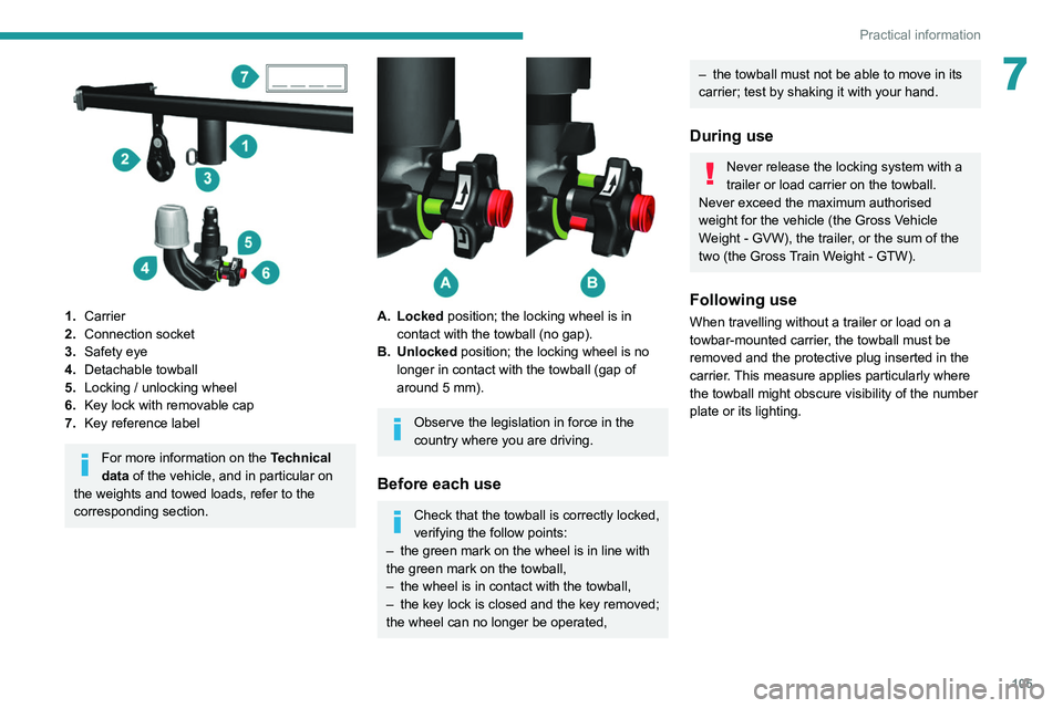
1.Carrier
2. Connection socket
3. Safety eye
4. Detachable towball
5. Locking / unlocking wheel
6. Key lock with removable cap
7. Key reference label
For more information on the Technical
data of the vehicle, and in particular on
the weights and towed loads, refer to the
corresponding section.
A. Locked position; the locking wheel is in contact with the towball (no gap).
B. Unlocked position; the locking wheel is no longer in contact with the towball (gap of
around 5 mm).
Observe the legislation in force in the
country where you are driving.
Before each use
Check that the towball is correctly locked,
verifying the follow points:
–
the green mark on the wheel is in line with
the green mark on the towball,
–
the wheel is in contact with the towball,
–
the key lock is closed and the key removed;
the wheel can no longer be operated,
– the towball must not be able to move in its
carrier; test by shaking it with your hand.
During use
Never release the locking system with a
trailer or load carrier on the towball.
Never exceed the maximum authorised
weight for the vehicle (the Gross Vehicle
Weight - GVW), the trailer, or the sum of the
two (the Gross Train Weight - GTW).
Following use
When travelling without a trailer or load on a
towbar-mounted carrier, the towball must be
removed and the protective plug inserted in the
carrier. This measure applies particularly where
the towball might obscure visibility of the number
plate or its lighting.
Page 108 of 212
106
Practical information
Fitting the towball
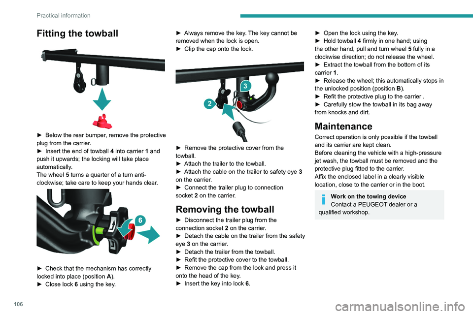
► Below the rear bumper, remove the protective
plug from the carrier.
►
Insert the end of towball
4 into carrier 1 and
push it upwards; the locking will take place
automatically.
The wheel 5 turns a quarter of a turn anti-
clockwise; take care to keep your hands clear.
► Check that the mechanism has correctly
locked into place (position A ).
►
Close lock 6
using the key. ►
Always remove the key
. The key cannot be
removed when the lock is open.
►
Clip the cap onto the lock.
► Remove the protective cover from the
towball.
►
Attach the trailer to the towball.
►
Attach the cable on the trailer to safety eye
3
on the carrier.
►
Connect the trailer plug to connection
socket
2 on the carrier.
Removing the towball
► Disconnect the trailer plug from the
connection socket 2 on the carrier.
►
Detach the cable on the trailer from the safety
eye
3 on the carrier.
►
Detach the trailer from the towball.
►
Refit the protective cover to the towball.
►
Remove the cap from the lock and press it
onto the head of the key
.
►
Insert the key into lock
6.
► Open the lock using the key .
► Hold towball 4
firmly in one hand; using
the other hand, pull and turn wheel 5 fully in a
clockwise direction; do not release the wheel.
►
Extract the towball from the bottom of its
carrier
1.
►
Release the wheel; this automatically stops in
the unlocked position (position
B
).
►
Refit the protective plug to the carrier .
►
Carefully stow the towball in its bag away
from knocks and dirt.
Maintenance
Correct operation is only possible if the towball
and its carrier are kept clean.
Before cleaning the vehicle with a high-pressure
jet wash, the towball must be removed and the
protective plug fitted to the carrier.
Affix the enclosed label in a clearly visible
location, close to the carrier or in the boot.
Work on the towing device
Contact a PEUGEOT dealer or a
qualified workshop.