2021 NISSAN FRONTIER light
[x] Cancel search: lightPage 334 of 492
The transfer case 4WD shif t switch is used
to select either 2WD or 4WD depending on
the driving conditions. There are three
types of drive modes available, 2WD, 4H and
4LO.
The 4WD shif t switch electronically controls
the transfer case operation. Rotate the
switch to move between each mode, 2WD,
4H and 4LO.
To change into or out of 4LO, the vehicle
MUST be stationary, move the shif t lever
to N (Neutral), and depress the brake
pedal. The switch must be depressed
and turned when changing into or out of
4LO.
WARNING
• When parking, apply the parking
brake before stopping the engine
and make sure that the 4WD shif t in-
dicator light is on and the ATP warn-
ing light goes off. Otherwise, the ve-
hicle could unexpectedly move even
if the A/T is in the P (Park) position. •
The transfer 4LO position indicator
light must stop blinking and remain
illuminated or turn off before shif ting
the transmission into gear. If the shif t
lever is shif ted from the N (Neutral)
position to any other gear when the
transfer 4LO position indicator light
is blinking, the vehicle may move
unexpectedly.
CAUTION
• Never shif t the 4WD shif t switch be-
tween 4LO and 4H while driving.
• The 4H position provides greater
traction. Avoid excessive speed, as it
will cause increased fuel consump-
tion and higher oil temperatures, and
could damage drivetrain compo-
nents. Speeds over 62 mph (100
km/h) in 4H is not recommended.
• The 4LO position provides maximum
power and traction. Avoid raising ve-
hicle speed excessively, as the maxi-
mum speed is approximately 31 mph
(50 km/h).
•
When driving straight, shif t the 4WD
shif t switch to the 2WD or 4H position.
Do not move the 4WD shif t switch
when making a turn or reversing.
• Do not shif t the 4WD shif t switch (be-
tween 2WD and 4H) while driving on
steep downhill grades. Use the en-
gine brake and low gears 2 (Second
gear) or 1 (Low gear), for engine
braking.
• Do not operate the 4WD shif t switch
(between 2WD and 4H) with the rear
wheels spinning.
• Do not drive on dry hard surface
roads in the 4H or 4LO position. Driv-
ing on dry hard surfaces in 4H or 4LO
may cause unnecessary noise and
tire wear. NISSAN recommends driv-
ing in the 2WD position under these
conditions.
• The 4WD transfer case may not be
shif ted between 4H and 4LO at low
ambient temperatures and the
transfer 4LO position indicator light
may blink even when the 4WD shif t
switch is shif ted. Af ter driving for a
while you can change the 4WD trans-
fer case between 4H and 4LO.
5-26Starting and driving
Page 336 of 492
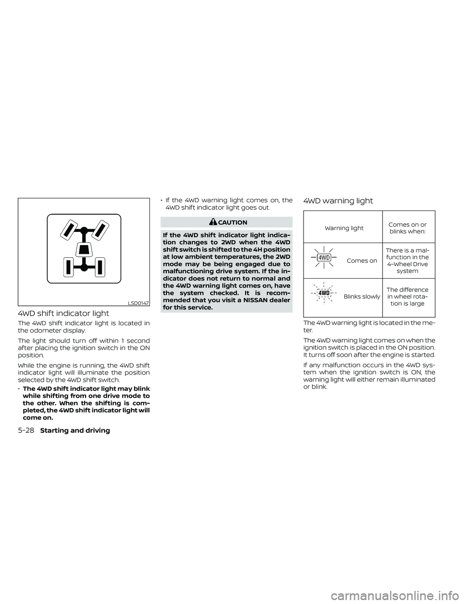
4WD shif t indicator light
The 4WD shif t indicator light is located in
the odometer display.
The light should turn off within 1 second
af ter placing the ignition switch in the ON
position.
While the engine is running, the 4WD shif t
indicator light will illuminate the position
selected by the 4WD shif t switch.
•The 4WD shif t indicator light may blink
while shif ting from one drive mode to
the other. When the shif ting is com-
pleted, the 4WD shif t indicator light will
come on. • If the 4WD warning light comes on, the
4WD shif t indicator light goes out.
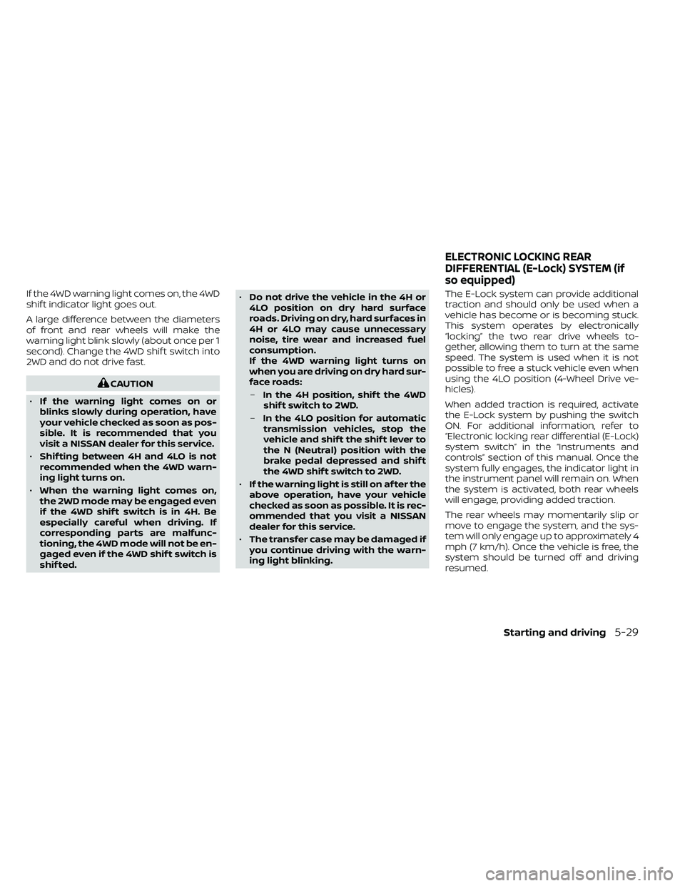
Warning light Comes on or
blinks when:
Comes on There is a mal-
function in the 4–Wheel Drive system
Blinks slowly The difference
in wheel rota- tion is large
The 4WD warning light is located in the me-
ter.
The 4WD warning light comes on when the
ignition switch is placed in the ON position.
It turns off soon af ter the engine is started.
If any malfunction occurs in the 4WD sys-
tem when the ignition switch is ON, the
warning light will either remain illuminated
or blink.
LSD0147
5-28Starting and driving
Page 337 of 492
If the 4WD warning light comes on, the 4WD
shif t indicator light goes out.
A large difference between the diameters
of front and rear wheels will make the
warning light blink slowly (about once per 1
second). Change the 4WD shif t switch into
2WD and do not drive fast.
Page 338 of 492
The Anti-Lock Braking (ABS) system is dis-
abled and the ABS light illuminates when
the E-Lock system is on. Also, the Vehicle
Dynamic Control (VDC) system is disabled
and the
indicator light illuminates
when the E-Lock system is on.
CAUTION
• Af ter using the E-Lock system, turn
the switch OFF to prevent possible
damage to driveline components
from extended use.
• Do not drive the vehicle at speeds
faster than 12 mph (20 km/h) when
the system is engaged. Doing so
could damage drivetrain
components.
• Do not turn on the E-Lock system
while the tires are spinning. Doing so
could damage drivetrain
components.
5-30Starting and driving
Page 343 of 492
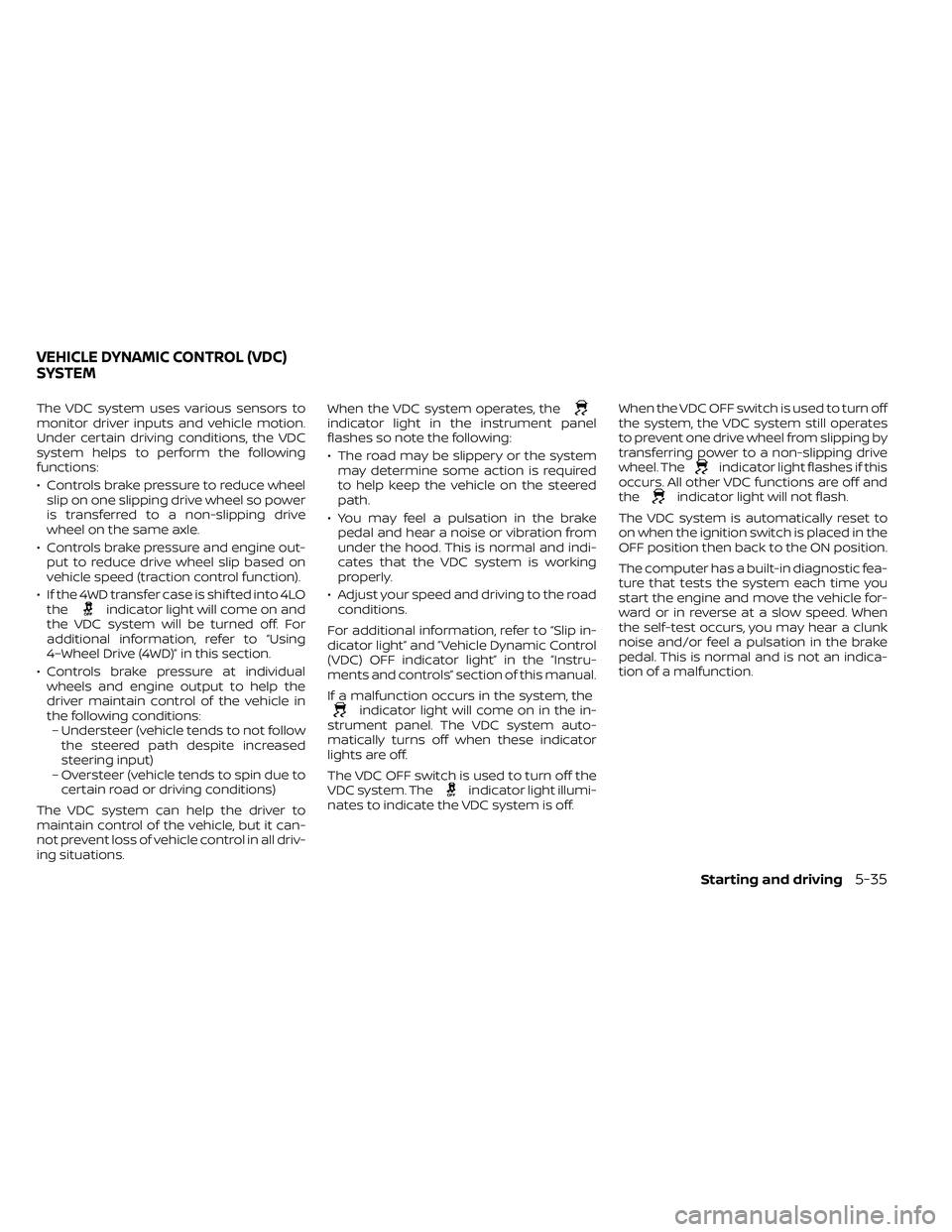
The VDC system uses various sensors to
monitor driver inputs and vehicle motion.
Under certain driving conditions, the VDC
system helps to perform the following
functions:
• Controls brake pressure to reduce wheelslip on one slipping drive wheel so power
is transferred to a non-slipping drive
wheel on the same axle.
• Controls brake pressure and engine out- put to reduce drive wheel slip based on
vehicle speed (traction control function).
• If the 4WD transfer case is shif ted into 4LO the
indicator light will come on and
the VDC system will be turned off. For
additional information, refer to “Using
4–Wheel Drive (4WD)” in this section.
• Controls brake pressure at individual wheels and engine output to help the
driver maintain control of the vehicle in
the following conditions:– Understeer (vehicle tends to not follow the steered path despite increased
steering input)
– Oversteer (vehicle tends to spin due to certain road or driving conditions)
The VDC system can help the driver to
maintain control of the vehicle, but it can-
not prevent loss of vehicle control in all driv-
ing situations. When the VDC system operates, the
indicator light in the instrument panel
flashes so note the following:
• The road may be slippery or the system
may determine some action is required
to help keep the vehicle on the steered
path.
• You may feel a pulsation in the brake pedal and hear a noise or vibration from
under the hood. This is normal and indi-
cates that the VDC system is working
properly.
• Adjust your speed and driving to the road conditions.
For additional information, refer to “Slip in-
dicator light” and ”Vehicle Dynamic Control
(VDC) OFF indicator light” in the ”Instru-
ments and controls” section of this manual.
If a malfunction occurs in the system, the
indicator light will come on in the in-
strument panel. The VDC system auto-
matically turns off when these indicator
lights are off.
The VDC OFF switch is used to turn off the
VDC system. The
indicator light illumi-
nates to indicate the VDC system is off. When the VDC OFF switch is used to turn off
the system, the VDC system still operates
to prevent one drive wheel from slipping by
transferring power to a non-slipping drive
wheel. The
indicator light flashes if this
occurs. All other VDC functions are off and
the
indicator light will not flash.
The VDC system is automatically reset to
on when the ignition switch is placed in the
OFF position then back to the ON position.
The computer has a built-in diagnostic fea-
ture that tests the system each time you
start the engine and move the vehicle for-
ward or in reverse at a slow speed. When
the self-test occurs, you may hear a clunk
noise and/or feel a pulsation in the brake
pedal. This is normal and is not an indica-
tion of a malfunction.
VEHICLE DYNAMIC CONTROL (VDC)
SYSTEM
Starting and driving5-35
Page 344 of 492

WARNING
• The VDC system is designed to help
the driver maintain stability but does
not prevent accidents due to abrupt
steering operation at high speeds or
by careless or dangerous driving
techniques. Reduce vehicle speed
and be especially careful when driv-
ing and cornering on slippery sur-
faces and always drive carefully.
• Do not modif y the vehicle's suspen-
sion. If suspension parts such as
shock absorbers, struts, springs, sta-
bilizer bars, bushings and wheels are
not NISSAN recommended for your
vehicle or are extremely deterio-
rated, the VDC system may not oper-
ate properly. This could adversely af-
fect vehicle handling performance,
and the
indicator light may flash
or theindicator light may
illuminate.
• If brake related parts such as brake
pads, rotors and calipers are not
NISSAN recommended or are ex-
tremely deteriorated, the VDC sys-
tem may not operate properly and
both the
andindicator
lights may illuminate. •
If engine control related parts are not
NISSAN recommended or are ex-
tremely deteriorated, both the
andindicator lights may
illuminate.
• When driving on extremely inclined
surfaces such as higher banked cor-
ners, the VDC system may not oper-
ate properly and the
indicator
light may flash or theindicator
light may illuminate. Do not drive on
these types of roads.
• When driving on an unstable surface
such as a turntable, ferry, elevator or
ramp, the
indicator light may
flash or theindicator light may
illuminate. This is not a malfunction.
Restart the engine af ter driving onto
a stable surface.
• If wheels or tires other than the
NISSAN recommended ones are
used, the VDC system may not oper-
ate properly and the
indicator
light may flash or theindicator
light may illuminate.
• The VDC system is not a substitute
for winter tires or tire chains on a
snow covered road.
BRAKE FORCE DISTRIBUTION
During braking while driving through turns,
the system optimizes the distribution of
force to each of the four wheels depending
on the radius of the turn.
indicator light may flash
or theindicator light may
illuminate.
5-36Starting and driving
Page 345 of 492
•If brake related parts such as brake
pads, rotors and calipers are not
NISSAN recommended or are ex-
tremely deteriorated, the VDC sys-
tem may not operate properly and
both the
and theindicator
lights may illuminate.
• If engine control related parts are not
NISSAN recommended or are ex-
tremely deteriorated, both the
andindicator lights may
illuminate.
• When driving on extremely inclined
surfaces such as higher banked cor-
ners, the VDC system may not oper-
ate properly and the
indicator
light may flash or theindicator
light may illuminate. Do not drive on
these types of roads.
• When driving on an unstable surface
such as a turntable, ferry, elevator or
ramp, the
indicator light may
flash or theindicator light may
illuminate. This is not a malfunction.
Restart the engine af ter driving onto
a stable surface. •
If wheels or tires other than the
NISSAN recommended ones are
used, the VDC system may not oper-
ate properly and the
indicator
light may flash or theindicator
light may illuminate.
• The VDC system is not a substitute
for winter tires or tire chains on a
snow covered road.
WARNING
• Never rely solely on the hill descent
control system to control vehicle
speed when driving on steep down-
hill grades. Always drive carefully and
attentively when using the hill de-
scent control system and decelerate
the vehicle speed by depressing the
brake pedal if necessary. Be espe-
cially careful when driving on frozen,
muddy or extremely steep downhill
roads. Failure to control vehicle
speed may result in a loss of control
of the vehicle and possible serious
injury or death.
• The hill descent control may not con-
trol the vehicle speed on a hill under
all load or road conditions. Always be
prepared to depress the brake pedal
to control vehicle speed. Failure to do
so may result in a collision or serious
personal injury.
The hill descent control system helps
maintain vehicle speed when driving under
15-21 mph (25-35 km/h) on steeper down-
hill grades. Hill descent control is useful
when engine braking alone in 4H or 4L can-
not control vehicle speed. Hill descent con-
trol applies the vehicle brakes to control
HILL DESCENT CONTROL SYSTEM (if
so equipped)
Starting and driving5-37
Page 346 of 492
vehicle speed allowing the driver to con-
centrate on steering while reducing the
burden of brake and accelerator operation.
• When additional braking is required onsteep downhill roads, activate the hill de-
scent control system by pushing the
switch on. For additional information, re-
fer to “Hill descent control switch” in the
“Instruments and controls” section of this
manual.
• Once the system is activated, the indica- tor light will remain on in the instrument
panel. For additional information, refer to
“Hill descent control system ON indicator
light” in the “Instruments and controls”
section of this manual.
If the accelerator or brake pedal is de-
pressed while the hill descent control sys-
tem is on, the system will stop operating
temporarily. As soon as the accelerator or
brake pedal is released, the hill descent
control system begins to function again if
the hill descent control operating condi-
tions are fulfilled.
For the best results, when descending
steep downhill grades, the hill descent con-
trol switch should be on and the shif t lever
in 2 (Second gear) or 1 (Low gear) for engine
braking.