2021 CHRYSLER 300 tow
[x] Cancel search: towPage 200 of 268
198 SERVICING AND MAINTENANCE
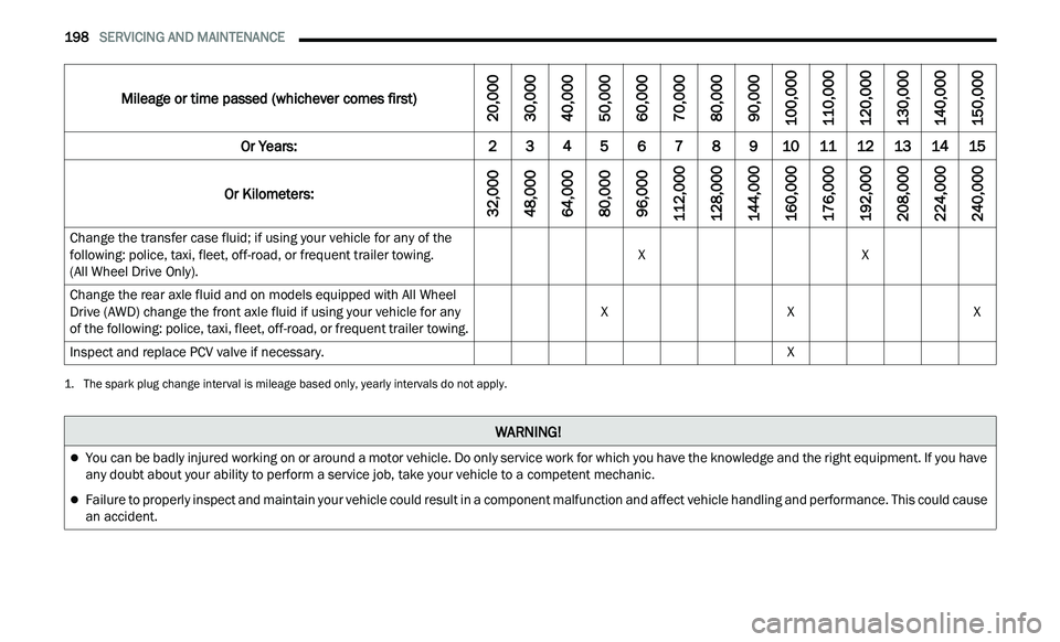
Change the transfer case fluid; if using your vehicle for any of the
following: police, taxi, fleet, off-road, or frequent trailer towing.
(All Wheel Drive Only). X
X
Change the rear axle fluid and on models equipped with All Wheel
D r
ive (AWD) change the front axle fluid if using your vehicle for any
of the following: police, taxi, fleet, off-road, or frequent trailer towing. X
XX
Inspect and replace PCV valve if necessary. X
1. The spark plug change interval is mileage based only, yearly intervals do not apply.
Mileage or time passed (whichever comes first)
20,000
30,000
40,000
50,000
60,000
70,000
80,000
90,000
100,000
110,000
120,000
130,000
140,000
150,000
Or Years: 2 3 4 5 6 7 8 9 10 11 12 13 14 15
Or Kilometers:
32,000
48,000
64,000
80,000
96,000
112,000
128,000
144,000
160,000
176,000
192,000
208,000
224,000
240,000
WARNING!
You can be badly injured working on or around a motor vehicle. Do only service work for which you have the knowledge and the right equipment. If you have
any doubt about your ability to perform a service job, take your vehicle to a competent mechanic.
Failure to properly inspect and maintain your vehicle could result in a component malfunction and affect vehicle handling and performance. This could cause
an accident.
Page 203 of 268
SERVICING AND MAINTENANCE 201
(Continued)
CHECKING OIL LEVEL
To ensure proper engine lubrication, the engine oil
must be maintained at the correct level. Check the
oil level at regular intervals, such as every month.
The best time to check the engine oil level is about
five minutes after a fully warmed up engine is shut
off.
Checking the oil while the vehicle is on level ground
w i
ll improve the accuracy of the oil level readings.
There are four possible dipstick types:
Crosshatched zone.
Crosshatched zone marked SAFE.
Crosshatched zone marked with MIN at the low
end of the range and MAX at the high end of the
range.
Crosshatched zone marked with dimples at the
MIN and the MAX ends of the range.
NOTE:
Always maintain the oil level within the crosshatch
m a
rkings on the dipstick.
Adding 1 quart (1.0 liters) of oil when the reading
is
at the low end of the dipstick range will raise the
oil level to the high end of the range marking.
ADDING WASHER FLUID
The windshield washer fluid reservoir is located in
the front of the engine compartment. Be sure to
check the fluid level at regular intervals. Fill the
reservoir with windshield washer solvent (not
radiator antifreeze) and operate the system for a
few seconds to flush out the residual water.
When refilling the washer fluid reservoir, apply
s om
e washer fluid to a cloth or towel and wipe the
wiper blades clean. This will help blade
performance.
To prevent freeze-up of your windshield washer
sy
stem in cold weather, select a solution or mixture
that meets or exceeds the temperature range of
your climate. This rating information can be found
on most washer fluid containers.
The fluid reservoir will hold nearly 1 gallon (4 liters)
of
washer fluid when the message “Low Washer
Fluid” appears in the instrument cluster.
MAINTENANCE-FREE BATTERY
Your vehicle is equipped with a maintenance-free
battery. You will never have to add water, nor is
periodic maintenance required.
NOTE:
The battery is stored under an access cover in the
t r
unk. Remote battery terminals are located in the
engine compartment for jump starting
Ú page 186.
CAUTION!
Overfilling or underfilling the crankcase will
cause aeration or loss of oil pressure. This could
damage your engine.
WARNING!
Commercially available windshield washer
solvents are flammable. They could ignite and
burn you. Care must be exercised when filling or
working around the washer solution.
WARNING!
Battery fluid is a corrosive acid solution and
can burn or even blind you. Do not allow
battery fluid to contact your eyes, skin, or
clothing. Do not lean over a battery when
attaching clamps. If acid splashes in eyes or
on skin, flush the area immediately with large
amounts of water
Ú page 186.
8
Page 207 of 268
SERVICING AND MAINTENANCE 205
(Continued)
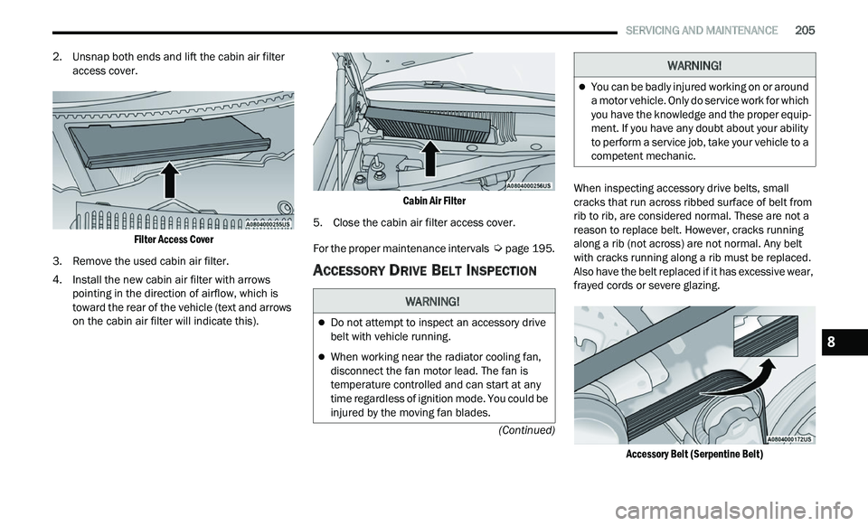
2. Unsnap both ends and lift the cabin air filter access cover.
Filter Access Cover
3. R emove the used cabin air filter.
4
. I nstall the new cabin air filter with arrows
p
ointing in the direction of airflow, which is
toward the rear of the vehicle (text and arrows
on the cabin air filter will indicate this).
Cabin Air Filter
5. Close the cabin air filter access cover.
F
or the proper maintenance intervals
Ú page 195.
ACCESSORY DRIVE BELT INSPECTION
When inspecting accessory drive belts, small
cracks that run across ribbed surface of belt from
rib to rib, are considered normal. These are not a
reason to replace belt. However, cracks running
along a rib (not across) are not normal. Any belt
with cracks running along a rib must be replaced.
Also have the belt replaced if it has excessive wear,
frayed cords or severe glazing.
Accessory Belt (Serpentine Belt)
WARNING!
Do not attempt to inspect an accessory drive
belt with vehicle running.
When working near the radiator cooling fan,
disconnect the fan motor lead. The fan is
temperature controlled and can start at any
time regardless of ignition mode. You could be
injured by the moving fan blades.
You can be badly injured working on or around
a motor vehicle. Only do service work for which
you have the knowledge and the proper equip -
ment. If you have any doubt about your ability
t o
perform a service job, take your vehicle to a
competent mechanic.
WARNING!
8
Page 209 of 268
SERVICING AND MAINTENANCE 207
Wiper Blade Removal/Installation
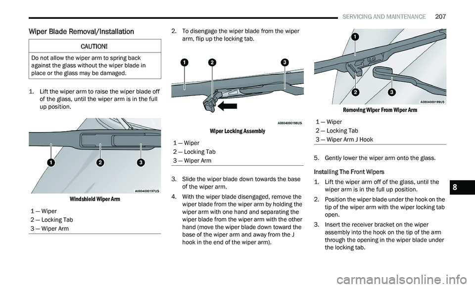
1. Lift the wiper arm to raise the wiper blade off
of the glass, until the wiper arm is in the full
up position.
Windshield Wiper Arm
2. T
o disengage the wiper blade from the wiper
a
rm, flip up the locking tab.
Wiper Locking Assembly
3. S lide the wiper blade down towards the base
of
the wiper arm.
4. With the wiper blade disengaged, remove the w
iper blade from the wiper arm by holding the
wiper arm with one hand and separating the
wiper blade from the wiper arm with the other
hand (move the wiper blade down toward the
base of the wiper arm and away from the J
hook in the end of the wiper arm).
Removing Wiper From Wiper Arm
5. G ently lower the wiper arm onto the glass.
I
nstalling The Front Wipers
1. Lift the wiper arm off of the glass, until the w
iper arm is in the full up position.
2. Position the wiper blade under the hook on the t
ip of the wiper arm with the wiper locking tab
open.
3. I nsert the receiver bracket on the wiper
a
ssembly into the hook on the tip of the arm
through the opening in the wiper blade under
the locking tab.
CAUTION!
Do not allow the wiper arm to spring back
against the glass without the wiper blade in
place or the glass may be damaged.
1 — Wiper
2 — Locking Tab
3 — Wiper Arm
1 — Wiper
2 — Locking Tab
3 — Wiper Arm
1 — Wiper
2 — Locking Tab
3 — Wiper Arm J Hook
8
Page 211 of 268
SERVICING AND MAINTENANCE 209
In unusual situations involving grossly
malfunctioning engine operation, a scorching odor
may suggest severe and abnormal catalyst
overheating. If this occurs, stop the vehicle, turn off
the engine and allow it to cool. Service, including a
tune-up to manufacturer's specifications, should
be obtained immediately.
To minimize the possibility of catalytic converter
da
mage:
Do not shut off the engine or interrupt the igni -
tion when the transmission is in gear and the
v e
hicle is in motion.
Do not try to start the engine by pushing or
towing the vehicle.
Do not idle the engine with any spark plug wires
disconnected or removed, such as when diag -
nostic testing, or for prolonged periods during
ve
ry rough idle or malfunctioning operating
conditions.
NOTE:
Your vehicle’s exhaust system may be equipped
w i
th an Electronic Exhaust Valve (EEV) system, if
the exhaust system is replaced with aftermarket
products a Malfunction Indicator Lamp (MIL) will
illuminate.
COOLING SYSTEM
Coolant Checks
Check engine coolant (antifreeze) protection every
12 months (before the onset of freezing weather,
w h
ere applicable). If the engine coolant is dirty, the
system should be drained, flushed, and refilled
with fresh Organic Additive Technology (OAT)
coolant (conforming to MS.90032) by an authorized dealer. Check the front of the radiator
for any accumulation of bugs, leaves, etc. If dirty,
clean by gently spraying water from a garden hose
vertically down the face of the condenser.
Check the coolant recovery bottle tubing for brittle
r
u
bber, cracking, tears, cuts, and tightness of the
connection at the bottle and radiator. Inspect the
entire system for leaks. DO NOT REMOVE THE
COOLANT PRESSURE CAP WHEN THE COOLING
SYSTEM IS HOT.
Cooling System — Drain, Flush And Refill
NOTE:
Some vehicles require special tools to add coolant
p r
operly. Failure to fill these systems properly
could lead to severe internal engine damage. If any
coolant is needed to be added to the system
please contact an authorized dealer.
If the engine coolant (antifreeze) is dirty or
c on
tains visible sediment, have an authorized
dealer clean and flush with Organic Additive
Technology (OAT) coolant (conforming to
MS.90032).
For the proper maintenance intervals
Ú page 195.
WARNING!
You or others can be badly burned by hot
engine coolant (antifreeze) or steam from your
radiator. If you see or hear steam coming from
under the hood, do not open the hood until the
radiator has had time to cool. Never open a
cooling system pressure cap when the radi
-
ator or coolant bottle is hot.
Keep hands, tools, clothing, and jewelry away
from the radiator cooling fan when the hood is
raised. The fan starts automatically and may
start at any time, whether the engine is
running or not.
When working near the radiator cooling fan,
disconnect the fan motor lead or turn the igni -
tion to the OFF mode. The fan is temperature
c on
trolled and can start at any time the igni -
tion is in the ON mode.
8
Page 231 of 268
SERVICING AND MAINTENANCE 229
Tire Loading And Tire Pressure
NOTE:
The proper cold tire inflation pressure is listed on
t h
e driver’s side B-pillar or the rear edge of the
driver's side door.
Check the inflation pressure of each tire, including
t h
e spare tire (if equipped), at least monthly and
inflate to the recommended pressure for your
vehicle.
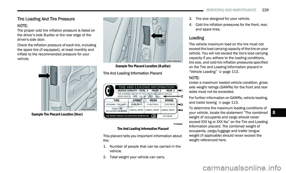
Example Tire Placard Location (Door) Example Tire Placard Location (B-pillar)
Tire And Loading Information Placard
Tire And Loading Information Placard
This placard tells you important information about
t h
e:
1. Number of people that can be carried in the ve
hicle.
2. Total weight your vehicle can carry. 3
. T
ire size designed for your vehicle.
4
. C old tire inflation pressures for the front, rear,
a
nd spare tires.
Loading
The vehicle maximum load on the tire must not
exceed the load carrying capacity of the tire on your
vehicle. You will not exceed the tire's load carrying
capacity if you adhere to the loading conditions,
tire size, and cold tire inflation pressures specified
on the Tire and Loading Information placard in
“Vehicle Loading”
Ú page 113.
NOTE:
Under a maximum loaded vehicle condition, gross
a x
le weight ratings (GAWRs) for the front and rear
axles must not be exceeded.
For further information on GAWRs, vehicle loading,
a n
d trailer towing Ú page 113.
To determine the maximum loading conditions of
y ou
r vehicle, locate the statement “The combined
weight of occupants and cargo should never
exceed XXX kg or XXX lbs” on the Tire and Loading
Information placard. The combined weight of
occupants, cargo/luggage and trailer tongue
weight (if applicable) should never exceed the
weight referenced here.8
Page 232 of 268
230 SERVICING AND MAINTENANCE
Steps For Determining Correct Load
Limit—
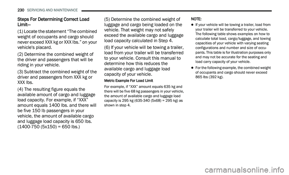
(1) Locate the statement “The combined
we
ight of occupants and cargo should
never exceed XXX kg or XXX lbs.” on your
vehicle's placard.
(2) Determine the combined weight of
th
e driver and passengers that will be
riding in your vehicle.
(3) Subtract the combined weight of the
dri
ver and passengers from XXX kg or
XXX lbs.
(4) The resulting figure equals the
av
ailable amount of cargo and luggage
load capacity. For example, if “XXX”
amount equals 1400 lbs. and there will
be five 150 lb passengers in your
vehicle, the amount of available cargo
and luggage load capacity is 650 lbs.
(1400-750 (5x150) = 650 lbs.) (5) Determine the combined weight of
l
u
ggage and cargo being loaded on the
vehicle. That weight may not safely
exceed the available cargo and luggage
load capacity calculated in Step 4.
(6) If your vehicle will be towing a trailer,
lo
ad from your trailer will be transferred
to your vehicle. Consult this manual to
determine how this reduces the
available cargo and luggage load
capacity of your vehicle.
Metric Example For Load Limit
For example, if “XXX” amount equals 635 kg and
t h
ere will be five 68 kg passengers in your vehicle,
the amount of available cargo and luggage load
capacity is 295 kg (635-340 (5x68) = 295 kg) as
shown in step 4.
NOTE:
If your vehicle will be towing a trailer, load from
your trailer will be transferred to your vehicle.
The following table shows examples on how to
calculate total load, cargo/luggage, and towing
capacities of your vehicle with varying seating
configurations and number and size of occu -
pants. This table is for illustration purposes only
a n
d may not be accurate for the seating and
load carry capacity of your vehicle.
For the following example, the combined weight
of occupants and cargo should never exceed
865 lbs (392 kg).
Page 236 of 268
234 SERVICING AND MAINTENANCE
It is not recommended driving a vehicle loaded at
full capacity or to tow a trailer while a tire is in the
run flat mode.
See the Tire Pressure Monitoring section for more
in
formation.
Tire Spinning
When stuck in mud, sand, snow, or ice conditions,
do not spin your vehicle's wheels above 30 mph
( 4
8 km/h) or for longer than 30 seconds
c on
tinuously without stopping.
For further information
Ú page 192.
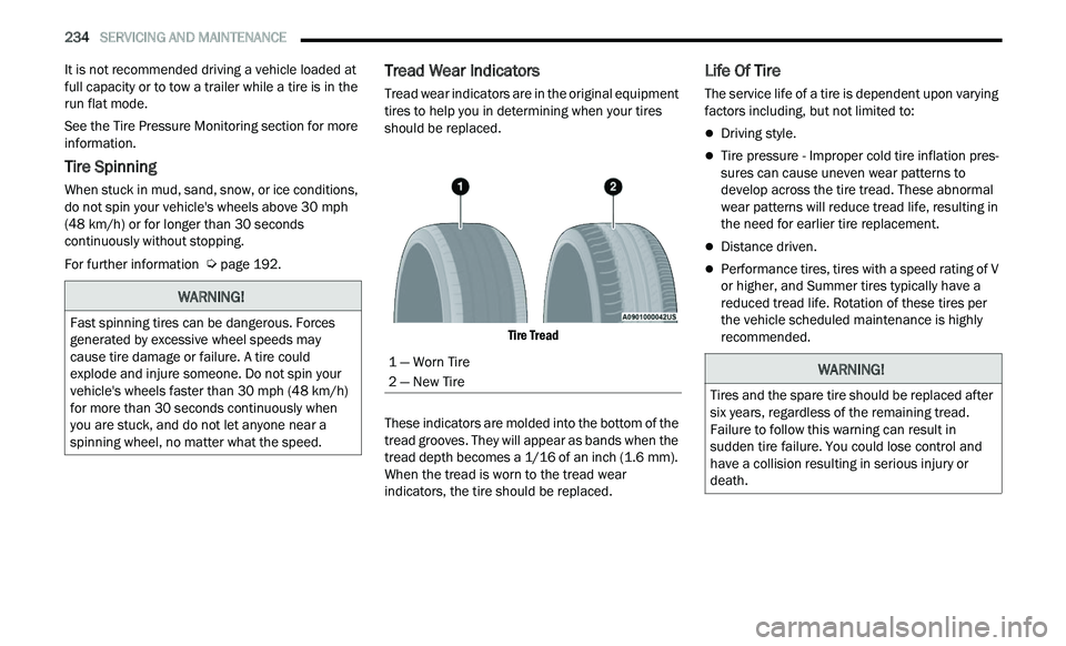
Tread Wear Indicators
Tread wear indicators are in the original equipment
tires to help you in determining when your tires
should be replaced.
Tire Tread
These indicators are molded into the bottom of the
tr
ead grooves. They will appear as bands when the
tread depth becomes a 1/16 of an inch (1.6 mm).
Wh
en the tread is worn to the tread wear
indicators, the tire should be replaced.
Life Of Tire
The service life of a tire is dependent upon varying
factors including, but not limited to:
Driving style.
Tire pressure - Improper cold tire inflation pres -
sures can cause uneven wear patterns to
d e
velop across the tire tread. These abnormal
wear patterns will reduce tread life, resulting in
the need for earlier tire replacement.
Distance driven.
Performance tires, tires with a speed rating of V
or higher, and Summer tires typically have a
reduced tread life. Rotation of these tires per
the vehicle scheduled maintenance is highly
recommended.
WARNING!
Fast spinning tires can be dangerous. Forces
generated by excessive wheel speeds may
cause tire damage or failure. A tire could
explode and injure someone. Do not spin your
vehicle's wheels faster than 30 mph (48 km/h)
for
more than 30 seconds continuously when
you are stuck, and do not let anyone near a
spinning wheel, no matter what the speed.
1 — Worn Tire
2 — New TireWARNING!
Tires and the spare tire should be replaced after
six years, regardless of the remaining tread.
Failure to follow this warning can result in
sudden tire failure. You could lose control and
have a collision resulting in serious injury or
death.