2021 CHRYSLER 300 tow
[x] Cancel search: towPage 6 of 268

4
STARTING AND OPERATING
STARTING THE ENGINE ......................................... 81
Automatic Transmission .. ...............................81
Keyless Enter ‘n Go™ — Ignition. . ....................81
Normal Starting . . ..............................................81
AutoPark . ..........................................................82
C old Weather Operation (Below –22°F Or
−30°C) . ............................................................83
I
f Engine Fails To Start . . ...................................83
After Starting. . ...................................................84
ENGINE BLOCK HEATER — IF EQUIPPED . . ......... 84
ENGINE BREAK-IN RECOMMENDATIONS .. ......... 84
PARKING BRAKE .. ................................................. 84
AUTOMATIC TRANSMISSION.. .............................. 85
Ignition Park Interlock .. ....................................86
Brake Transmission Shift Interlock (BTSI)
System . .............................................................87
8
-Speed Automatic Transmission . . .................87
SPORT MODE — IF EQUIPPED . . ............................ 91
FUEL SAVER TECHNOLOGY 5.7L ONLY —
IF EQUIPPED ..
......................................................... 92
POWER STEERING .. ............................................... 92
CRUISE CONTROL SYSTEMS — IF EQUIPPED .. . 92
Cruise Control .. ................................................92
Adaptive Cruise Control (ACC) . . .......................94PARKSENSE FRONT AND REAR PARK
ASSIST — IF EQUIPPED. .
..................................... 103
ParkSense Sensors .. ..................................... 103
ParkSense Display . . ...................................... 103
ParkSense Warning Display . . ....................... 106
Enabling And Disabling ParkSense . . ............ 106
Service The ParkSense Park Assist
System . .......................................................... 106
C
leaning The ParkSense System . . ............... 107
ParkSense System Usage Precautions. . ...... 107
LANESENSE — IF EQUIPPED . . ........................... 108
LaneSense Operation .. ................................. 108
Turning LaneSense On Or Off . . ..................... 108
LaneSense Warning Message . . .................... 108
Changing LaneSense Status . . ...................... 110
PARKVIEW REAR BACK UP CAMERA. . ............. 110
REFUELING THE VEHICLE .. ................................. 111
Emergency Fuel Filler Door Release .. .......... 112
VEHICLE LOADING . . ............................................ 113
Vehicle Certification Label .. .......................... 113
Gross Vehicle Weight Rating (GVWR) . . ........ 113
Gross Axle Weight Rating (GAWR) . . ............. 113
Overloading. . .................................................. 113
Loading . ......................................................... 113 T RAILER TOWING .
.
.............................................. 114
Common Towing Definitions.. ....................... 114
Trailer Hitch Classification. . .......................... 115
Trailer Towing Weights (Maximum Trailer
Weight Ratings) . .
........................................... 116
Trailer And Tongue Weight . . ........................ 116
Towing Requirements . . ................................. 116
Towing Tips . . ................................................. 118
RECREATIONAL TOWING (BEHIND
MOTORHOME) . .
.................................................... 119
DRIVING TIPS .. ..................................................... 119
Driving On Slippery Surfaces .. ...................... 119
Driving Through Water . . ............................... 120
MULTIMEDIA
UCONNECT SYSTEMS ......................................... 121
CYBERSECURITY ................................................. 121
UCONNECT SETTINGS .. ...................................... 122
Customer Programmable Features —
Uconnect 4C/4C NAV Settings . .
.................. 122
RADIO OPERATION AND MOBILE PHONES. . .... 136
Regulatory And Safety Information .. ............ 136
Page 7 of 268

5
SAFETY
SAFETY FEATURES .............................................. 137
Anti-Lock Brake System (ABS) .. ................... 137
Electronic Brake Control (EBC) System . . ..... 138
AUXILIARY DRIVING SYSTEMS . . ........................ 142
Blind Spot Monitoring (BSM) —
If Equipped. .
................................................... 142
Forward Collision Warning (FCW) With
Mitigation Operation — If Equipped. .
............ 146
Tire Pressure Monitoring System (TPMS) . . .. 148
OCCUPANT RESTRAINT SYSTEMS . . .................. 151
Occupant Restraint Systems Features .. ..... 151
Important Safety Precautions. . ..................... 152
Seat Belt Systems . . ...................................... 152
Supplemental Restraint Systems (SRS) . . .... 158
Child Restraints . . ........................................... 166
SAFETY TIPS . . ....................................................... 176
Transporting Passengers .. ............................ 176
Transporting Pets . . ........................................ 176
Safety Checks You Should Make Inside
The Vehicle . .
................................................. 176
Periodic Safety Checks You Should Make
Outside The Vehicle . .
.................................... 177
Exhaust Gas . . ................................................ 178
Carbon Monoxide Warnings . . ....................... 178
IN CASE OF EMERGENCY
HAZARD WARNING FLASHERS......................... 179
ASSIST AND SOS MIRROR — IF EQUIPPED .. ... 179
JACKING AND TIRE CHANGING .. ....................... 182
Preparations For Jacking .. ........................... 182
Jack Location/Spare Tire Stowage . . ............ 183
Jacking And Changing A Tire . . ..................... 184
JUMP STARTING . . ............................................... 186
Preparations For Jump Start .. ...................... 187
Jump Starting Procedure . . ............................ 188
REFUELING IN AN EMERGENCY –
IF EQUIPPED . .
..................................................... 189
IF YOUR ENGINE OVERHEATS .. ........................ 190
MANUAL PARK RELEASE .. ................................ 190
FREEING A STUCK VEHICLE .. ............................ 192
TOWING A DISABLED VEHICLE .. ....................... 193
All Wheel Drive (AWD) Models .. .................... 194
Rear Wheel Drive (RWD) Models . . ............... 194
ENHANCED ACCIDENT RESPONSE SYSTEM
(EARS) . ................................................................. 194
E
VENT DATA RECORDER (EDR) .. ...................... 194
SERVICING AND MAINTENANCE
SCHEDULED SERVICING ................................... 195
Maintenance Plan .. ....................................... 196
ENGINE COMPARTMENT . . .................................. 199
3.6L Engine .. ................................................ 199
5.7L Engine . . ................................................ 200
Checking Oil Level . . ....................................... 201 Adding Washer Fluid .
.
................................... 201
Maintenance-Free Battery . . ......................... 201
Pressure Washing . . ....................................... 202
VEHICLE MAINTENANCE . . .................................. 202
Engine Oil ...................................................... 202
E ngine Oil Filter . . ........................................... 203
Engine Air Cleaner Filter . . ............................. 203
Air Conditioner Maintenance. . ...................... 204
Accessory Drive Belt Inspection . . ................. 205
Body Lubrication . . ......................................... 206
Windshield Wiper Blades. . ............................ 206
Exhaust System . . ........................................... 208
Cooling System . . ........................................... 209
Brake System . . ............................................. 212
Automatic Transmission . . ............................ 212
All Wheel Drive (AWD) — If Equipped . . ........ 213
Rear Axle. ....................................................... 213
F uses. ............................................................. 214
B ulb Replacement . . ...................................... 221
TIRES . .................................................................... 225
T ire Safety Information .. ............................... 225
Tires — General Information . . ...................... 232
Tire Types. ...................................................... 235
S pare Tires — If Equipped. . ........................... 236
Wheel And Wheel Trim Care. . ....................... 238
Snow Traction Devices. . ................................ 239
Tire Rotation Recommendations . . .............. 240
Page 25 of 268

GETTING TO KNOW YOUR VEHICLE 23
CHILD-PROTECTION DOOR LOCK
S
YSTEM — REAR DOORS
To provide a safer environment for small children
riding in the rear seats, the rear doors are
equipped with Child-Protection Door Lock system.
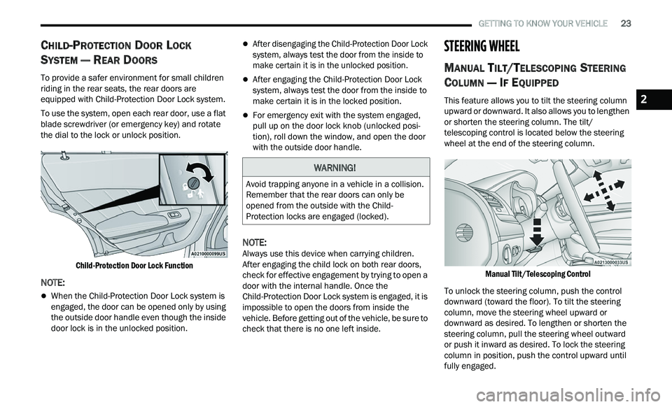
To use the system, open each rear door, use a flat
b l
ade screwdriver (or emergency key) and rotate
the dial to the lock or unlock position.
Child-Protection Door Lock Function
NOTE:
When the Child-Protection Door Lock system is
engaged, the door can be opened only by using
the outside door handle even though the inside
door lock is in the unlocked position.
After disengaging the Child-Protection Door Lock
system, always test the door from the inside to
make certain it is in the unlocked position.
After engaging the Child-Protection Door Lock
system, always test the door from the inside to
make certain it is in the locked position.
For emergency exit with the system engaged,
pull up on the door lock knob (unlocked posi -
tion), roll down the window, and open the door
w i
th the outside door handle.
NOTE:
Always use this device when carrying children.
A f
ter engaging the child lock on both rear doors,
check for effective engagement by trying to open a
door with the internal handle. Once the
Child-Protection Door Lock system is engaged, it is
impossible to open the doors from inside the
vehicle. Before getting out of the vehicle, be sure to
check that there is no one left inside.
STEERING WHEEL
MANUAL TILT/TELESCOPING STEERING
C
OLUMN — IF EQUIPPED
This feature allows you to tilt the steering column
upward or downward. It also allows you to lengthen
or shorten the steering column. The tilt/
telescoping control is located below the steering
wheel at the end of the steering column.
Manual Tilt/Telescoping Control
To unlock the steering column, push the control
dow
nward (toward the floor). To tilt the steering
column, move the steering wheel upward or
downward as desired. To lengthen or shorten the
steering column, pull the steering wheel outward
or push it inward as desired. To lock the steering
column in position, push the control upward until
fully engaged.
WARNING!
Avoid trapping anyone in a vehicle in a collision.
Remember that the rear doors can only be
opened from the outside with the Child-
Protection locks are engaged (locked).
2
Page 34 of 268

32 GETTING TO KNOW YOUR VEHICLE
(Continued)
NOTE:
The engine must be running for the ventilated
s e
ats to operate.
For information on use with the Remote Start
sy
stem, see Ú page 17.
HEAD RESTRAINTS
Head restraints are designed to reduce the risk of
injury by restricting head movement in the event of
a rear impact. Head restraints should be adjusted
so that the top of the head restraint is located
above the top of your ear.
NOTE:
Do not reverse the head restraints (making the
r e
ar of the head restraint face forward) in an
attempt to gain additional clearance to the back of
your head.
Reactive Head Restraints — Front Seats
The front driver and passenger seats are equipped
with Reactive Head Restraints (RHR). In the event
of a rear impact, the RHR will automatically extend
forward minimizing the gap between the back of
the occupant’s head and the RHR.
The RHR will automatically return to their normal
p os
ition following a rear impact. If the RHR do not
return to their normal position, see an authorized
dealer immediately.
To raise the head restraint, pull upward on the
he
ad restraint. To lower the head restraint, push
the adjustment button located at the base of the
head restraint and push downward on the head
restraint.
Front Head Restraint
WARNING!
All occupants, including the driver, should not
operate a vehicle or sit in a vehicle’s seat until
the head restraints are placed in their proper
positions in order to minimize the risk of neck
injury in the event of a crash.
Head restraints should never be adjusted
while the vehicle is in motion. Driving a vehicle
with the head restraints improperly adjusted
or removed could cause serious injury or
death in the event of a collision.
1 — Release Button
2 — Adjustment Button
WARNING!
A loose head restraint thrown forward in a
collision or hard stop could cause serious
injury or death to occupants of the vehicle.
Always securely stow removed head restraints
in a location outside the occupant compart
-
ment.
ALL the head restraints MUST be reinstalled in
the vehicle to properly protect the occupants.
Follow the reinstallation instructions above
prior to operating the vehicle or occupying a
seat.
Page 35 of 268

GETTING TO KNOW YOUR VEHICLE 33
Rear Head Restraints
The center head restraint has two adjustable
positions: up or down. When the center seat is
being occupied, the head restraint should be in the
raised position. When there are no occupants in
the center seat, the head restraint can be lowered
for maximum visibility for the driver.
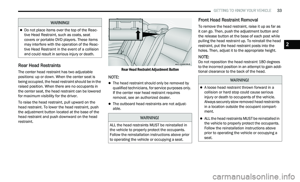
To raise the head restraint, pull upward on the
he
ad restraint. To lower the head restraint, push
the adjustment button located at the base of the
head restraint and push downward on the head
restraint.
Rear Head Restraint Adjustment Button
NOTE:
The head restraint should only be removed by
qualified technicians, for service purposes only.
If the center rear head restraint requires
removal, see an authorized dealer.
The outboard head restraints are not adjust
-
able.
Front Head Restraint Removal
To remove the head restraint, raise it up as far as
it can go. Then, push the adjustment button and
the release button at the base of each post while
pulling the head restraint up. To reinstall the head
restraint, put the head restraint posts into the
holes. Then, adjust it to the appropriate height.
NOTE:
Do not reposition the head restraint 180 degrees
t o
the incorrect position in an attempt to gain addi -
tional clearance to the back of the head.
Do not place items over the top of the Reac -
tive Head Restraint, such as coats, seat
c ov
ers or portable DVD players. These items
may interfere with the operation of the Reac -
tive Head Restraint in the event of a collision
a n
d could result in serious injury or death.
WARNING!
WARNING!
ALL the head restraints MUST be reinstalled in
the vehicle to properly protect the occupants.
Follow the reinstallation instructions above prior
to operating the vehicle or occupying a seat.
WARNING!
A loose head restraint thrown forward in a
collision or hard stop could cause serious
injury or death to occupants of the vehicle.
Always securely stow removed head restraints
in a location outside the occupant compart -
ment.
ALL the head restraints MUST be reinstalled in
the vehicle to properly protect the occupants.
Follow the reinstallation instructions above
prior to operating the vehicle or occupying a
seat.
2
Page 36 of 268

34 GETTING TO KNOW YOUR VEHICLE
MIRRORS
INSIDE REARVIEW MIRROR
Automatic Dimming Mirror
The rearview mirror can be adjusted up, down, left,
and right. The mirror should be adjusted to center
on the view through the rear window.
This mirror automatically adjusts for headlight
gl
are from vehicles behind you.
NOTE:
The Automatic Dimming Mirror feature is disabled
w h
en the vehicle is in REVERSE to improve the
driver’s rear view.
The Automatic Dimming feature can be turned on
or
off through the Uconnect system Ú page 122.
Automatic Dimming Mirror
ILLUMINATED VANITY MIRRORS
To access an illuminated vanity mirror, flip down
one of the visors and lift the cover.
Illuminated Vanity Mirror
Sun Visor “Slide-On-Rod” Feature
The sun visor “Slide-On-Rod” feature allows for
additional flexibility in positioning the sun visor to
block out the sun.
1. Fold down the sun visor.
2
. U nclip the visor from the corner clip.
3
. P ivot the sun visor toward the side window.
4
. E xtend the sun visor for additional sun
b
lockage.
Slide-On-Rod Feature
NOTE:
The sun visor can also be extended while the sun
v i
sor is against the windshield for additional sun
blockage through the front of the vehicle.
CAUTION!
To avoid damage to the mirror during cleaning,
never spray any cleaning solution directly onto
the mirror. Apply the solution onto a clean cloth
and wipe the mirror clean.
Page 43 of 268

GETTING TO KNOW YOUR VEHICLE 41
DAYTIME RUNNING LIGHTS (DRLS)
The Daytime Running Lights will turn on when the
engine is started and will remain on unless the
headlights are turned to the on position, the
parking brake is applied, or the ignition is placed in
the OFF position.
NOTE:
For vehicles sold in Canada, the Daytime
Running Lights will automatically deactivate
when the front fog lights are turned on.
If allowed by law in the country in which the
vehicle was purchased, the Daytime Running
Lights can be turned on and off using the
Uconnect system
Ú page 122.
On some vehicles, the Daytime Running Lights
may deactivate or reduce intensity on one side
of the vehicle (when a turn signal is activated on
that side), or on both sides of the vehicle (when
the hazard warning lights are activated).
HIGH/LOW BEAM SWITCH
Push the multifunction lever toward the instrument
panel to switch the headlights to high beams.
Pulling the multifunction lever back will turn the
low beams on.
AUTOMATIC HIGH BEAM — IF EQUIPPED
The Automatic High Beam Headlamp Control
system provides increased forward lighting at night
by automating high beam control through the use
of a digital camera mounted on the inside rearview
mirror. This camera detects vehicle specific light
and automatically switches from high beams to low
beams until the approaching vehicle is out of view.
NOTE:
The Automatic High Beam Headlamp Control
can be turned on or off by selecting or dese
-
lecting “Auto High Beam” within Uconnect
Se
ttings Ú page 122, as well as turning the
headlight switch to the AUTO position.
Broken, muddy, or obstructed headlights and
taillights of vehicles in the field of view will
cause headlights to remain on longer (closer to
the vehicle). Also, dirt, film, and other obstruc -
tions on the windshield or camera lens will
c a
use the system to function improperly.
If the windshield or Automatic High Beam Head -
lamp Control mirror is replaced, the mirror must
b e
re-aimed to ensure proper performance. See
a local authorized dealer.
FLASH-TO-PASS
You can signal another vehicle with your headlights
by lightly pulling the multifunction lever toward you. This will cause the high beam headlights to turn on,
and remain on, until the lever is released.
AUTOMATIC HEADLIGHTS
This system automatically turns the headlights on
or off according to ambient light levels. To turn the
system on, rotate the headlight switch
counterclockwise to the AUTO position. When the
system is on, the headlight time delay feature is
also on. This means the headlights will stay on for
up to 90 seconds after placing the ignition in the
OFF position. The headlight time delay can be
programmed 0/30/60/90 seconds within
Uconnect Settings
Ú page 122.
To turn the automatic system off, move the
h e
adlight switch out of the AUTO position.
NOTE:
The engine must be running before the headlights
w i
ll come on in the automatic mode.
PARKING LIGHTS
To turn on the parking lights and instrument panel
lights, rotate the headlight switch clockwise. To
turn off the parking lights, rotate the headlight
switch back to the O (off) position.
NOTE:
For vehicles sold in Canada, rotate the headlight
s w
itch to the AUTO position to turn off the parking
lights.
2
Page 47 of 268

GETTING TO KNOW YOUR VEHICLE 45
Instrument Panel Dimmer Control
Instrument Panel Dimmer Control
(V
ehicles Sold In Canada Only)
WINDSHIELD WIPERS AND WASHERS
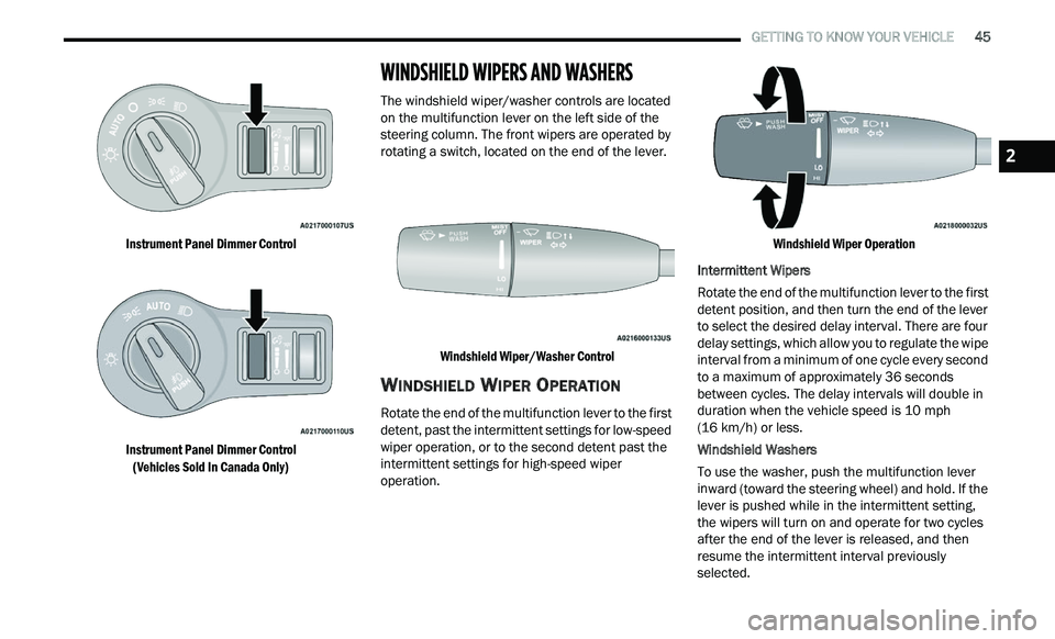
The windshield wiper/washer controls are located
on the multifunction lever on the left side of the
steering column. The front wipers are operated by
rotating a switch, located on the end of the lever.
Windshield Wiper/Washer Control
WINDSHIELD WIPER OPERATION
Rotate the end of the multifunction lever to the first
detent, past the intermittent settings for low-speed
wiper operation, or to the second detent past the
intermittent settings for high-speed wiper
operation.
Windshield Wiper Operation
Intermittent Wipers
Rotate the end of the multifunction lever to the first
de
tent position, and then turn the end of the lever
to select the desired delay interval. There are four
delay settings, which allow you to regulate the wipe
interval from a minimum of one cycle every second
to a maximum of approximately 36 seconds
between cycles. The delay intervals will double in
duration when the vehicle speed is 10 mph
( 1
6 km/h) or less.
Windshield Washers
To use the washer, push the multifunction lever
i n
ward (toward the steering wheel) and hold. If the
lever is pushed while in the intermittent setting,
the wipers will turn on and operate for two cycles
after the end of the lever is released, and then
resume the intermittent interval previously
selected.
2