2021 CHRYSLER 300 radio
[x] Cancel search: radioPage 124 of 268
122 MULTIMEDIA
UCONNECT SETTINGS
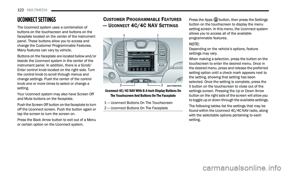
The Uconnect system uses a combination of
buttons on the touchscreen and buttons on the
faceplate located on the center of the instrument
panel. These buttons allow you to access and
change the Customer Programmable Features.
Many features can vary by vehicle.
Buttons on the faceplate are located below and/or
be
side the Uconnect system in the center of the
instrument panel. In addition, there is a Scroll/
Enter control knob located on the right side. Turn
the control knob to scroll through menus and
change settings. Push the center of the control
knob one or more times to select or change a
setting.
Your Uconnect system may also have Screen Off
a n
d Mute buttons on the faceplate.
Push the Screen Off button on the faceplate to turn
off
the Uconnect screen. Push the button again or
tap the screen to turn the screen on.
Press the Back Arrow button to exit out of a Menu
or
certain option on the Uconnect system.
CUSTOMER PROGRAMMABLE FEATURES
— U
CONNECT 4C/4C NAV SETTINGS
Uconnect 4C/4C NAV With 8.4-inch Display Buttons On
The Touchscreen And Buttons On The Faceplate
Press the Apps
button, then press the Settings
button on the touchscreen to display the menu
s e
tting screen. In this menu, the Uconnect system
allows you to access all of the available
programmable features.
NOTE:
Depending on the vehicle’s options, feature
s e
ttings may vary.
When making a selection, press the button on the
tou
chscreen to enter the desired menu. Once in
the desired menu, press and release the preferred
setting option until a check mark appears next to
the setting, showing that setting has been
selected. Once the setting is complete, press the
X button on the touchscreen to close out of the
s e
ttings screen. Pressing the Up or Down Arrow
button on the right side of the screen will allow you
to toggle up or down through the available settings.
The following tables list the settings that may be
fou
nd within the Uconnect 4C/4C NAV radio, along
with the selectable options pertaining to each
setting.
1 — Uconnect Buttons On The Touchscreen
2 — Uconnect Buttons On The Faceplate
Page 128 of 268
126 MULTIMEDIA
Camera
Set Time Hours This setting will allow you to set the hours. Sync Time With GPS must be off for
t
h
is setting to be available. The “+” setting will increase the hours. The “-”
setting will decrease the hours.
Set Time Minutes This setting will allow you to set the minutes. Sync Time With GPS must be off
for
this setting to be available. The “+” setting will increase the minutes. The
“-” setting will decrease the minutes.
Show Time in Status Bar This setting will place the time in the radio’s status bar.
Setting Name Description
When the Camera button is pressed on the touchscreen, the system displays the options related to the vehicle’s camera features.
NOTE:
Depending on the vehicle’s options, feature settings may vary.
Setting Name Description
ParkView Backup Camera DelayThis setting will add a delay to the ParkView Backup Camera when shifting out
of
REVERSE.
Active ParkView Backup Camera Guidelines This setting will turn the Active ParkView Backup Camera Guidelines on or off.
Page 132 of 268
130 MULTIMEDIA
Doors & Locks
When the Doors & Locks button is pressed on the touchscreen, the system displays the options related to locking and unlocking the vehicle’s doors.
NOTE:
Depending on the vehicle’s options, feature settings may vary.
Setting Name Description
Auto Unlock On ExitThis setting will unlock the doors when any of the doors are opened from the
i
n
side.
Flash Lights With Lock This setting will allow you to turn on or off the flashing of the lights when the
Loc
k
button is pushed on the key fob. Available settings are “On” and “Off”.
Sound Horn With Lock This setting will sound the horn when the Lock button is pushed on the key
f
ob
. The “Off” setting will not sound the horn when the Lock button is pushed.
The “1st Press” setting will sound the horn when the Lock button is pushed
once. The “2nd Press” setting will sound the horn when the Lock button is
pushed twice.
Sound Horn With Remote Start This setting will sound the horn when the remote start is activated from the
ke
y fob.
1st Press Of Key Fob Unlocks This setting will change how many pushes of the Unlock button on the key fob
a
r
e needed to open all the doors. The “Driver Door” setting will only unlock the
driver door on the first push on the Unlock button. The “All Doors” setting will
unlock all doors on the first push of the Unlock button.
Passive Entry This setting will allow you to turn the Passive Entry feature (Keyless Enter ‘n
G
o™
) on or off.
Personal Settings Linked To Key Fob This setting will recall preset radio stations and driver seat position that have
b
e
en linked to the key fob.
Page 136 of 268
134 MULTIMEDIA
SiriusXM® Setup — If Equipped
NOTE:
A subscription to SiriusXM® Satellite Radio is required for these settings to be functional.
When the SiriusXM® Setup button is pressed on the touchscreen, the system displays options related to SiriusXM® Satellite Radio. These settings can be used
t o
skip specific radio channels and restart favorite songs from the beginning.
NOTE:
Depending on the vehicle’s options, feature settings may vary.
Setting Name Description
Tune StartThis setting will play the current song from the beginning when you tune to a
m
u
sic channel using one of the 12 presets.
Channel Skip This setting allows you to set channels that you wish to skip. A channel list will
d
i
splay of the skipped channels.
Subscription Information This menu provides SiriusXM® subscription information. SiriusXM® Travel
Li
n
k is a separate subscription.
Page 137 of 268
MULTIMEDIA 135
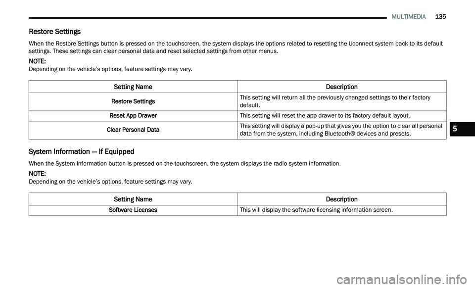
Restore Settings
System Information — If Equipped
When the Restore Settings button is pressed on the touchscreen, the system displays the options related to resetting the Uconnect system back to its default
settings. These settings can clear personal data and reset selected settings from other menus.
NOTE:
Depending on the vehicle’s options, feature settings may vary.
Setting Name Description
Restore SettingsThis setting will return all the previously changed settings to their factory
d
e
fault.
Reset App Drawer This setting will reset the app drawer to its factory default layout.
Clear Personal Data This setting will display a pop-up that gives you the option to clear all personal
d
a
ta from the system, including Bluetooth® devices and presets.
When the System Information button is pressed on the touchscreen, the system displays the radio system information.
NOTE:
Depending on the vehicle’s options, feature settings may vary.
Setting Name Description
Software LicensesThis will display the software licensing information screen.
5
Page 138 of 268
136 MULTIMEDIA
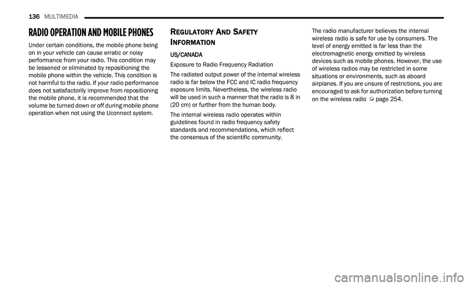
RADIO OPERATION AND MOBILE PHONES
Under certain conditions, the mobile phone being
on in your vehicle can cause erratic or noisy
performance from your radio. This condition may
be lessened or eliminated by repositioning the
mobile phone within the vehicle. This condition is
not harmful to the radio. If your radio performance
does not satisfactorily improve from repositioning
the mobile phone, it is recommended that the
volume be turned down or off during mobile phone
operation when not using the Uconnect system.
REGULATORY AND SAFETY
I
NFORMATION
US/CANADA
Exposure to Radio Frequency Radiation
The radiated output power of the internal wireless
r a
dio is far below the FCC and IC radio frequency
exposure limits. Nevertheless, the wireless radio
will be used in such a manner that the radio is 8 in
( 2
0 cm) or further from the human body.
The internal wireless radio operates within
gu
idelines found in radio frequency safety
standards and recommendations, which reflect
the consensus of the scientific community. The radio manufacturer believes the internal
w
i
reless radio is safe for use by consumers. The
level of energy emitted is far less than the
electromagnetic energy emitted by wireless
devices such as mobile phones. However, the use
of wireless radios may be restricted in some
situations or environments, such as aboard
airplanes. If you are unsure of restrictions, you are
encouraged to ask for authorization before turning
on the wireless radio
Ú page 254.
Page 139 of 268
137
(Continued)
SAFETY
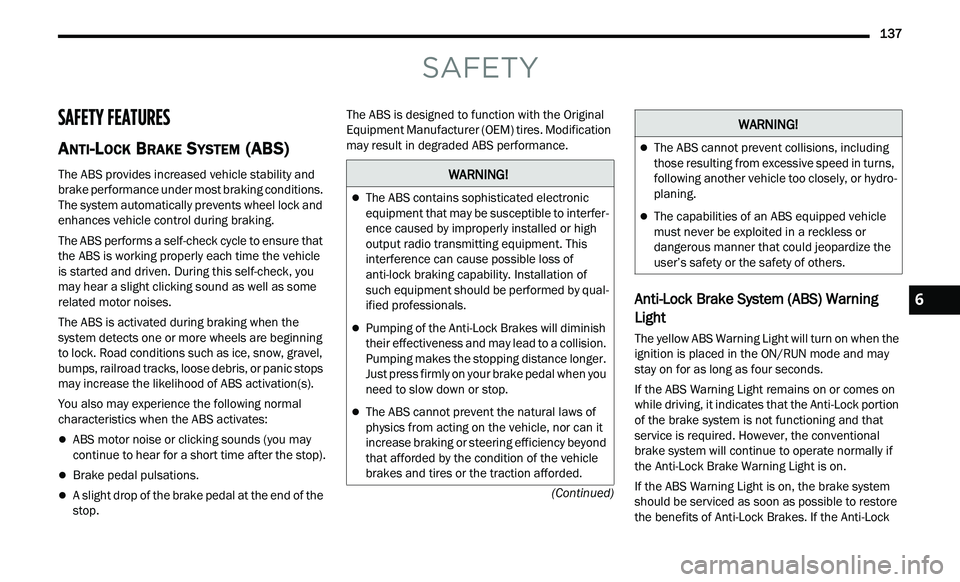
SAFETY FEATURES
ANTI-LOCK BRAKE SYSTEM (ABS)
The ABS provides increased vehicle stability and
brake performance under most braking conditions.
The system automatically prevents wheel lock and
enhances vehicle control during braking.
The ABS performs a self-check cycle to ensure that
th
e ABS is working properly each time the vehicle
is started and driven. During this self-check, you
may hear a slight clicking sound as well as some
related motor noises.
The ABS is activated during braking when the
s y
stem detects one or more wheels are beginning
to lock. Road conditions such as ice, snow, gravel,
bumps, railroad tracks, loose debris, or panic stops
may increase the likelihood of ABS activation(s).
You also may experience the following normal
c h
aracteristics when the ABS activates:
ABS motor noise or clicking sounds (you may
continue to hear for a short time after the stop).
Brake pedal pulsations.
A slight drop of the brake pedal at the end of the
stop. The ABS is designed to function with the Original
E
q
uipment Manufacturer (OEM) tires. Modification
may result in degraded ABS performance.
Anti-Lock Brake System (ABS) Warning
Light
The yellow ABS Warning Light will turn on when the
ignition is placed in the ON/RUN mode and may
stay on for as long as four seconds.
If the ABS Warning Light remains on or comes on
w h
ile driving, it indicates that the Anti-Lock portion
of the brake system is not functioning and that
service is required. However, the conventional
brake system will continue to operate normally if
the Anti-Lock Brake Warning Light is on.
If the ABS Warning Light is on, the brake system
s h
ould be serviced as soon as possible to restore
the benefits of Anti-Lock Brakes. If the Anti-Lock
WARNING!
The ABS contains sophisticated electronic
equipment that may be susceptible to interfer -
ence caused by improperly installed or high
out
put radio transmitting equipment. This
interference can cause possible loss of
anti-lock braking capability. Installation of
such equipment should be performed by qual -
ified professionals.
Pumping of the Anti-Lock Brakes will diminish
their effectiveness and may lead to a collision.
Pumping makes the stopping distance longer.
Just press firmly on your brake pedal when you
need to slow down or stop.
The ABS cannot prevent the natural laws of
physics from acting on the vehicle, nor can it
increase braking or steering efficiency beyond
that afforded by the condition of the vehicle
brakes and tires or the traction afforded.
The ABS cannot prevent collisions, including
those resulting from excessive speed in turns,
following another vehicle too closely, or hydro -
planing.
The capabilities of an ABS equipped vehicle
must never be exploited in a reckless or
dangerous manner that could jeopardize the
user’s safety or the safety of others.
WARNING!
6
Page 145 of 268

SAFETY 143
BSM Warning Light
The BSM detection zone covers approximately one
la
ne width on both sides of the vehicle 12 ft
( 3
.8 m). The zone length starts at the outside
r e
arview mirror and extends approximately 10 ft
( 3
m) beyond the rear fascia/bumper of the
v e
hicle. The BSM system monitors the detection
zones on both sides of the vehicle when the vehicle
speed reaches approximately 6 mph (10 km/h) or
h i
gher and will alert the driver of vehicles in these
areas.
NOTE:
The BSM system DOES NOT alert the driver
about rapidly approaching vehicles that are
outside the detection zones.
The BSM system detection zone DOES NOT
change if your vehicle is towing a trailer. There -
fore, visually verify the adjacent lane is clear for
b ot
h your vehicle and trailer before making a lane change. If the trailer or other object (i.e.,
bicycle, sports equipment) extends beyond the
side of your vehicle, this may result in the BSM
warning light randomly alerting on the trailer or
even remaining illuminated the entire time the
vehicle is in a forward gear
Ú page 122.
The Blind Spot Monitoring (BSM) system may
experience drop outs (blinking on and off) of the
side mirror warning indicator lamps when a
motorcycle or any small object remains at the
side of the vehicle for extended periods of time
(more than a couple of seconds).
The BSM system can become blocked if snow, ice,
mu
d, or other road contaminations accumulate on
the rear fascia/bumper where the radar sensors
are located. The system may also detect blockage
if the vehicle is operated in areas with extremely
low radar returns such as a desert or parallel to a
large elevation drop. If blockage is detected, a
“Blind Spot Temporarily Unavailable, Wipe Rear
Corners” message will display in the cluster, both
mirror lights will illuminate, and BSM and RCP
alerts will not occur. This is normal operation. The
system will automatically recover and resume
function when the condition clears. To minimize
system blockage, do not block the area of the rear
fascia/bumper where the radar sensors are
located with foreign objects (bumper stickers,
bicycle racks, etc.) and keep it clear of road
contaminations.
Sensor Location (Driver Side Shown)
The BSM system notifies the driver of objects in the
d e
tection zones by illuminating the BSM warning
light located in the outside mirrors in addition to
sounding an audible (chime) alert and reducing the
radio volume if the corresponding turn signal is
activated
Ú page 146.
The BSM system monitors the detection zone from
t h
ree different entry points (side, rear, front) while
driving to see if an alert is necessary. The BSM
system will issue an alert during these types of
zone entries.
6