2021 CHRYSLER 300 radio
[x] Cancel search: radioPage 41 of 268

GETTING TO KNOW YOUR VEHICLE 39
NOTE:
Canadian radio frequency laws require transmitter
s i
gnals to time-out (or quit) after several seconds
of transmission, which may not be long enough for
HomeLink® to pick up the signal during
programming. Similar to this Canadian law, some
U.S. gate operators are designed to time-out in the
same manner. The procedure may need to be
performed multiple times to successfully pair the
device to your HomeLink® buttons.
REPROGRAMMING A SINGLE
H
OMELINK® BUTTON
To reprogram a single HomeLink® button that has
been previously trained, without erasing all the
channels, follow the procedure below. Be sure to
determine whether the new device you want to
program the HomeLink® button to has a rolling
code or non-rolling code.
1. Place the ignition in the ON/RUN position,
w
ithout starting the engine.
2. Push and hold the desired HomeLink® button u
ntil the HomeLink® Indicator light begins to
flash after 20 seconds. Do not release the
button.
3. Without releasing the button ,
proceed with
Step 2 in “Programming HomeLink® To A
G a
rage Door Opener” and follow all remaining
steps.
CANADIAN/GATE OPERATOR
P
ROGRAMMING
For programming transmitters in Canada/United
States that require the transmitter signals to
“time-out” after several seconds of transmission.
Canadian Radio Frequency (RF) laws require
t r
ansmitter signals to time-out (or quit) after
several seconds of transmission – which may not
be long enough for HomeLink® to pick up the
signal during programming. Similar to this
Canadian law, some US gate operators are
designed to time-out in the same manner.
It may be helpful to unplug the device during the
c y
cling process to prevent possible overheating of
the garage door or gate motor.
1. P lace the ignition in the ON/RUN position.
2
. P lace the hand-held transmitter 1 to 3
inches
(3
to 8 cm) away from the HomeLink® button
you wish to program while keeping the
HomeLink® indicator light in view.
3. Continue to press and hold the HomeLink® bu
tton, while you press and release (cycle) your
hand-held transmitter every two seconds until
HomeLink® has successfully accepted the
frequency signal. The indicator light will flash
slowly and then rapidly when fully trained.
4. Watch for the HomeLink® indicator to change f
lash rates. When it changes, it is programmed. It may take up to 30 seconds or
longer in rare cases. The garage door may
open and close while you are programming.
5. P ress and hold the programmed HomeLink®
b
utton and observe the indicator light.
NOTE:
If the indicator light stays on constantly,
programming is complete and the garage
door/device should activate when the
HomeLink® button is pressed.
To program the two remaining HomeLink®
buttons, repeat each step for each remaining
button. DO NOT erase the channels.
If you unplugged the garage door opener/device
f or
programming, plug it back in at this time.
Reprogramming A Single HomeLink® Button
(C
anadian/Gate Operator)
To reprogram a channel that has been previously
tr
ained, follow these steps:
1. Place the ignition in the ON/RUN position.
2
. P ress and hold the desired HomeLink® button
u
ntil the indicator light begins to flash after 20
seconds. Do not release the button.
3. W ithout releasing the button, proceed with
“
Canadian/Gate Operator Programming”
step 2 and follow all remaining steps
Ú page 254.
2
Page 46 of 268
44 GETTING TO KNOW YOUR VEHICLE
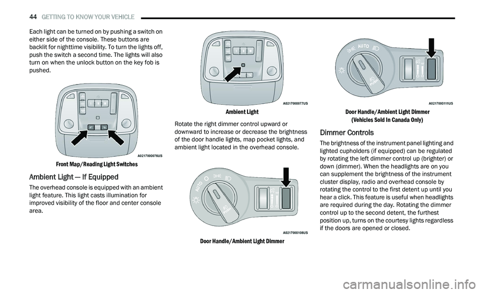
Each light can be turned on by pushing a switch on
either side of the console. These buttons are
backlit for nighttime visibility. To turn the lights off,
push the switch a second time. The lights will also
turn on when the unlock button on the key fob is
pushed.
Front Map/Reading Light Switches
Ambient Light — If Equipped
The overhead console is equipped with an ambient
light feature. This light casts illumination for
improved visibility of the floor and center console
area.
Ambient Light
Rotate the right dimmer control upward or
d ow
nward to increase or decrease the brightness
of the door handle lights, map pocket lights, and
ambient light located in the overhead console.
Door Handle/Ambient Light Dimmer Door Handle/Ambient Light Dimmer
(V
ehicles Sold In Canada Only)
Dimmer Controls
The brightness of the instrument panel lighting and
lighted cupholders (if equipped) can be regulated
by rotating the left dimmer control up (brighter) or
down (dimmer). When the headlights are on you
can supplement the brightness of the instrument
cluster display, radio and overhead console by
rotating the control to the first detent up until you
hear a click. This feature is useful when headlights
are required during the day. Rotating the dimmer
control up to the second detent, the furthest
position up, turns on the courtesy lights regardless
if the doors are opened or closed.
Page 49 of 268
GETTING TO KNOW YOUR VEHICLE 47
The Rain Sensing system has protection features
for the wiper blades and arms, and will not operate
under the following conditions:
Low Ambient Temperature — When the ignition
is first placed in the ON position, the Rain
Sensing system will not operate until the wiper
switch is moved, vehicle speed is greater than
3 mph (5 km/h), or the outside temperature is
gr
eater than 32°F (0°C).
Transmission In NEUTRAL Position — When the
ignition is ON, and the automatic transmission
is in the NEUTRAL position, the Rain Sensing
system will not operate until the wiper switch is
moved, vehicle speed is greater than 3 mph
(5
km/h), or the gear selector is moved out of
t h
e NEUTRAL position.
Remote Start Mode Inhibit — On vehicles
equipped with a Remote Start system, Rain
Sensing wipers are not operational when the
vehicle is in Remote Start mode.
CLIMATE CONTROLS
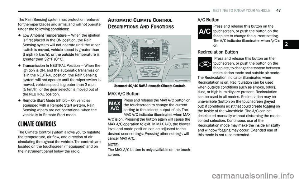
The Climate Control system allows you to regulate
the temperature, air flow, and direction of air
circulating throughout the vehicle. The controls are
located on the touchscreen (if equipped) and on
the instrument panel below the radio.
AUTOMATIC CLIMATE CONTROL
D
ESCRIPTIONS AND FUNCTIONS
Uconnect 4C/4C NAV Automatic Climate Controls
MAX A/C Button
Press and release the MAX A/C button on
the touchscreen to change the current
s e
tting to the coldest output of air. The
MAX A/C indicator illuminates when MAX
A/C is on. Pressing the button again will cause the
MAX A/C operation to exit. In MAX A/C, the blower
level and mode position can be adjusted to the
desired user settings. Pressing other settings will
cancel MAX A/C.
NOTE:
The MAX A/C button is only available on the touch -
screen.
A/C Button
Press and release this button on the
touchscreen, or push the button on the
f a
ceplate to change the current setting.
The A/C indicator illuminates when A/C is
on.
Recirculation Button
Press and release this button on the
touchscreen, or push the button on the
f a
ceplate, to change the system between
recirculation mode and outside air mode.
The Recirculation indicator illuminates when
Recirculation is on. Recirculation can be used
when outside conditions such as smoke, odors,
dust, or high humidity are present. Recirculation
can be used in all modes. Recirculation may be
unavailable (button on the touchscreen greyed
out) if conditions exist that could create fogging on
the inside of the windshield. The A/C can be
deselected manually without disturbing the mode
control selection. Continuous use of the
Recirculation mode may make the inside air stuffy
and window fogging may occur. Extended use of
this mode is not recommended.
2
Page 71 of 268
GETTING TO KNOW YOUR INSTRUMENT PANEL 69
The ACC screen may display once again if any ACC
activity occurs, which may include any of the
following:
Distance Setting Change
System Cancel
Driver Override
System Off
ACC Proximity Warning
ACC Unavailable Warning
LaneSense — If Equipped
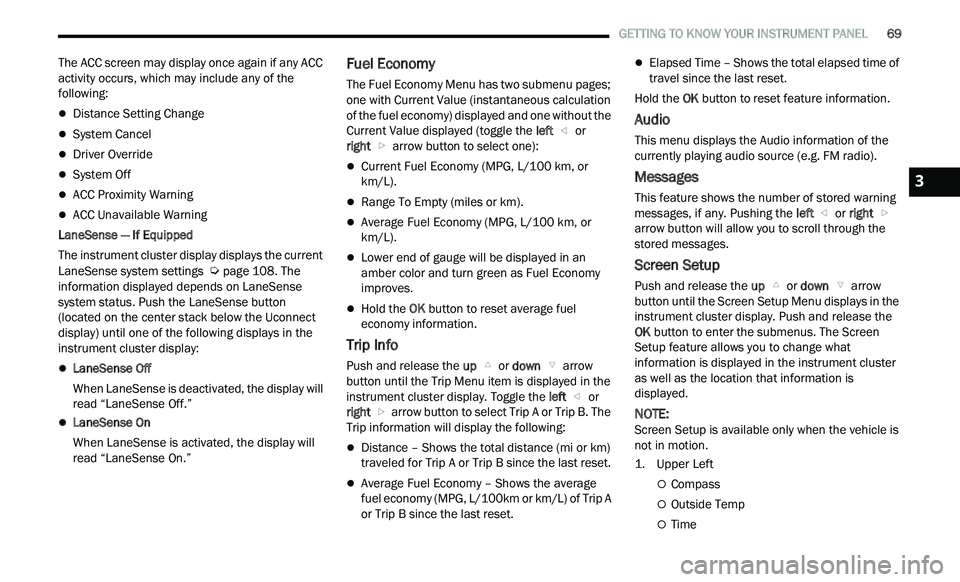
The instrument cluster display displays the current
La n
eSense system settings Ú page 108. The
information displayed depends on LaneSense
s y
stem status. Push the LaneSense button
(located on the center stack below the Uconnect
display) until one of the following displays in the
instrument cluster display:
LaneSense Off
When LaneSense is deactivated, the display will
r e
ad “LaneSense Off.”
LaneSense On
When LaneSense is activated, the display will
re
ad “LaneSense On.”
Fuel Economy
The Fuel Economy Menu has two submenu pages;
one with Current Value (instantaneous calculation
of the fuel economy) displayed and one without the
Current Value displayed (toggle the left
or
right arrow button to select one):
Current Fuel Economy (MPG, L/100 km, or
km/L).
Range To Empty (miles or km).
Average Fuel Economy (MPG, L/100 km, or
km/L).
Lower end of gauge will be displayed in an
amber color and turn green as Fuel Economy
improves.
Hold the OK button to reset average fuel
economy information.
Trip Info
Push and release the up or down arrow
button until the Trip Menu item is displayed in the
i n
strument cluster display. Toggle the left
or
right arrow button to select Trip A or Trip B. The
Trip information will display the following:
Distance – Shows the total distance (mi or km)
traveled for Trip A or Trip B since the last reset.
Average Fuel Economy – Shows the average
fuel economy (MPG, L/100km or km/L) of Trip A
or Trip B since the last reset.
Elapsed Time – Shows the total elapsed time of
travel since the last reset.
Hold the OK
button to reset feature information.
Audio
This menu displays the Audio information of the
currently playing audio source (e.g. FM radio).
Messages
This feature shows the number of stored warning
messages, if any. Pushing the left
or right
a
rrow button will allow you to scroll through the
s t
ored messages.
Screen Setup
Push and release the up or down arrow
button until the Screen Setup Menu displays in the
i n
strument cluster display. Push and release the
OK button to enter the submenus. The Screen
Setup feature allows you to change what
information is displayed in the instrument cluster
as well as the location that information is
displayed.
NOTE:
Screen Setup is available only when the vehicle is
n ot
in motion.
1. Upper Left
Compass
Outside Temp
Time
3
Page 73 of 268
GETTING TO KNOW YOUR INSTRUMENT PANEL 71
NOTE:
The charging system is independent from load
reduction. The charging system performs a diag
-
nostic on the charging system continuously.
If the Battery Charge Warning Light is on it may
indicate a problem with the charging system
Ú page 73.
The electrical loads that may be switched off (if
e q
uipped), and vehicle functions which can be
affected by load reduction:
Heated Seat/Vented Seats/Heated Wheel —
If Equipped
Heated/Cooled Cup Holders — If Equipped
Rear Defroster And Heated Mirrors
HVAC System
115 Volts AC Power Inverter System
Audio and Telematics System
Loss of the battery charge may indicate one or
m or
e of the following conditions:
The charging system cannot deliver enough
electrical power to the vehicle system because
the electrical loads are larger than the capability
of the charging system. The charging system is
still functioning properly.
Turning on all possible vehicle electrical loads
(e.g. HVAC to max settings, exterior and interior
lights, overloaded power outlets +12 Volts, 115 Volts AC, USB ports) during certain driving
c
on
ditions (city driving, towing, frequent stop -
ping).
Installing options like additional lights, upfitter
electrical accessories, audio systems, alarms
and similar devices.
Unusual driving cycles (short trips separated by
long parking periods).
The vehicle was parked for an extended period
of time (weeks, months).
The battery was recently replaced and was not
charged completely.
The battery was discharged by an electrical load
left on when the vehicle was parked.
The battery was used for an extended period
with the engine not running to supply radio,
lights, chargers, +12 Volt portable appliances
like vacuum cleaners, game consoles and
similar devices.
What to do when an electrical load reduction
a c
tion message is present (“Battery Saver On” or
“Battery Saver Mode”)
During a trip:
Reduce power to unnecessary loads if possible:
Turn off redundant lights (interior or exte -
rior)
Check what may be plugged in to power
outlets +12 Volts, 115 Volts AC, USB ports
Check HVAC settings (blower, temperature)
Check the audio settings (volume)
After a trip:
Check if any aftermarket equipment was
installed (additional lights, upfitter electrical
accessories, audio systems, alarms) and review
specifications if any (load and Ignition Off Draw
currents).
Evaluate the latest driving cycles (distance,
driving time and parking time).
The vehicle should have service performed if
the message is still present during consecutive
trips and the evaluation of the vehicle and
driving pattern did not help to identify the cause.
PROGRAMMABLE FEATURES
The instrument cluster display can be used to view
or change the following settings. Push the up
or
down arrow button to scroll through the main
menus, then push the ri
ght arrow button to
scroll through the submenus of each menu item.
P u
sh the left arrow button to scroll back to a
previous menu or submenu.
WARNING LIGHTS AND MESSAGES
The warning/indicator lights will illuminate in the
instrument panel together with a dedicated
message and/or acoustic signal when applicable.
These indications are indicative and precautionary
3
Page 107 of 268
STARTING AND OPERATING 105
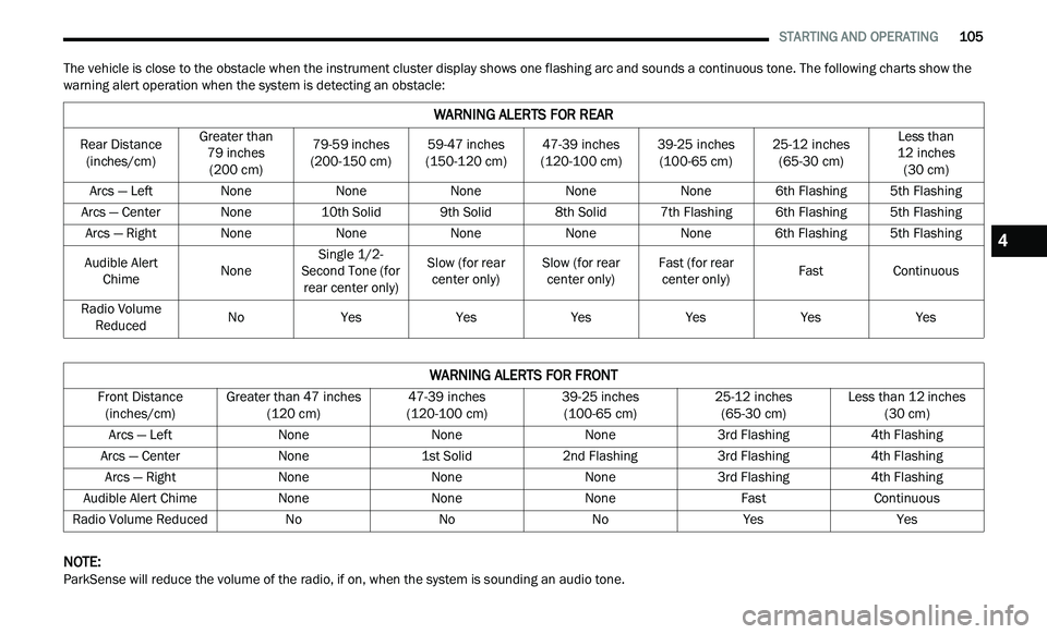
The vehicle is close to the obstacle when the instrument cluster display shows one flashing arc and sounds a continuous tone. The following charts show the
warning alert operation when the system is detecting an obstacle:
NOTE:
ParkSense will reduce the volume of the radio, if on, when the system is sounding an audio tone.
WARNING ALERTS FOR REAR
Rear Distance (inches/cm) Greater than
79
inches
( 2
00 cm) 79-59
inches
( 2
00-150 cm) 59-47
inches
(1
50-120 cm) 47-39
inches
(1
20-100 cm) 39-25
inches
(1
00-65 cm) 25-12
inches
(6
5-30 cm) Less than
1 2
inches
( 3
0 cm)
Arcs — Left NoneNoneNoneNoneNone6th Flashing 5th Flashing
Arcs — Center None10th Solid 9th Solid8th Solid7th Flashing 6th Flashing5th Flashing
Arcs — Right NoneNoneNoneNoneNone6th Flashing 5th Flashing
Audible Alert Ch
ime NoneSingle 1/2-
S e
cond Tone (for
rear center only) Slow (for rear
c e
nter only) Slow (for rear
ce nter only) Fast (for rear
ce nter only) Fast
Continuous
Radio Volume Re
duced No
Yes YesYesYesYesYes
WARNING ALERTS FOR FRONT
Front Distance
(inches/cm) Greater than 47
inches
(1
20 cm) 47-39
inches
(1
20-100 cm) 39-25
inches
(1
00-65 cm) 25-12
inches
(6
5-30 cm) Less than 12
inches
(3
0 cm)
Arcs — Left NoneNoneNone3rd Flashing 4th Flashing
Arcs — Center None1st Solid2nd Flashing 3rd Flashing4th Flashing
Arcs — Right NoneNoneNone3rd Flashing 4th Flashing
Audible Alert C h
ime None NoneNone FastContinuous
Radio Volume Reduced NoNoNoYes Yes
4
Page 109 of 268

STARTING AND OPERATING 107
(Continued)
CLEANING THE PARKSENSE SYSTEM
Clean the ParkSense sensors with water, car wash
soap and a soft cloth. Do not use rough or hard
cloths. Do not scratch or poke the sensors.
Otherwise, you could damage the sensors.
PARKSENSE SYSTEM USAGE
P
RECAUTIONS
NOTE:
Ensure that the front and rear bumpers are free
of snow, ice, mud, dirt and debris to keep the
ParkSense system operating properly.
Jackhammers, large trucks, and other vibra -
tions could affect the performance of Park -
Sense.
When you turn ParkSense off, the instrument
cluster will display “PARKSENSE OFF.” Once you
turn ParkSense off, it remains off until you turn
it on again, even if you cycle the ignition.
When you move the gear selector to the
REVERSE position and ParkSense is turned off,
the instrument cluster will display “PARKSENSE
OFF” for as long as the vehicle is in REVERSE.
ParkSense, when on, will reduce the volume of
the radio when it is sounding a tone.
Clean the ParkSense sensors regularly, taking
care not to scratch or damage them. The
sensors must not be covered with ice, snow, slush, mud, dirt or debris. Failure to do so can
result in the system not working properly. The
ParkSense system might not detect an obstacle
behind or in front of the fascia/bumper, or it
could provide a false indication that an obstacle
is behind or in front of the fascia/bumper.
Use the ParkSense switch to turn the ParkSense
system off if objects such as bicycle carriers,
trailer hitches, etc., are placed within 12
inches
(3
0 cm) from the rear fascia/bumper. Failure to
do so can result in the system misinterpreting a
close object as a sensor problem, causing the
“PARKSENSE UNAVAILABLE SERVICE
REQUIRED” message to be displayed in the
instrument cluster.
WARNING!
Drivers must be careful when backing up even
when using ParkSense. Always check carefully
behind your vehicle, look behind you, and be
sure to check for pedestrians, animals, other
vehicles, obstructions, and blind spots before
backing up. You are responsible for safety and
must continue to pay attention to your
surroundings. Failure to do so can result in
serious injury or death.
Before using ParkSense, it is strongly recom -
mended that the ball mount and hitch ball
a s
sembly be disconnected from the vehicle
when the vehicle is not used for towing.
Failure to do so can result in injury or damage
to vehicles or obstacles because the hitch ball
will be much closer to the obstacle than the
rear fascia/bumper when the vehicle sounds
the continuous tone. Also, the sensors could
detect the ball mount and hitch ball assembly,
depending on its size and shape, giving a false
indication that an obstacle is behind the
vehicle.
CAUTION!
ParkSense is only a parking aid and it is
unable to recognize every obstacle, including
small obstacles. Parking curbs might be
temporarily detected or not detected at all.
Obstacles located above or below the sensors
will not be detected when they are in close
proximity.
The vehicle must be driven slowly when using
ParkSense in order to be able to stop in time
when an obstacle is detected. It is recom -
mended that the driver looks over his/her
s h
oulder when using ParkSense.
WARNING!
4
Page 112 of 268
110 STARTING AND OPERATING
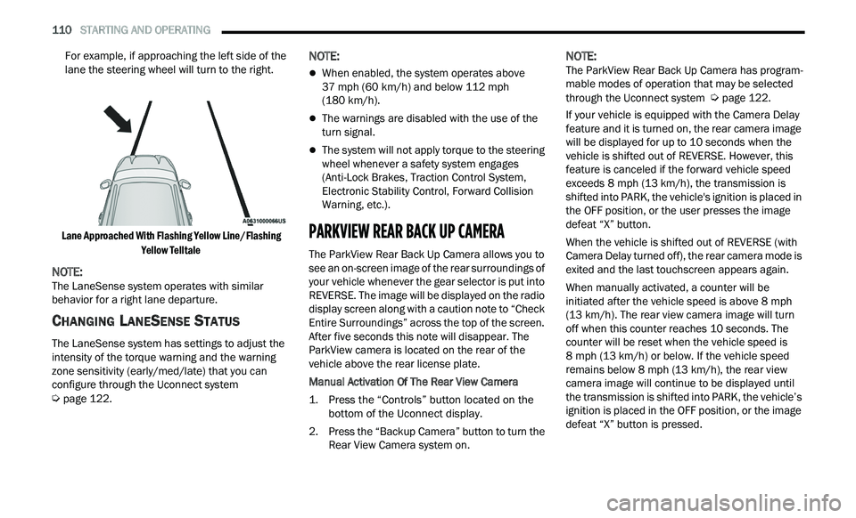
For example, if approaching the left side of the
lane the steering wheel will turn to the right.
Lane Approached With Flashing Yellow Line/Flashing Ye
llow Telltale
NOTE:
The LaneSense system operates with similar
b e
havior for a right lane departure.
CHANGING LANESENSE STATUS
The LaneSense system has settings to adjust the
intensity of the torque warning and the warning
zone sensitivity (early/med/late) that you can
configure through the Uconnect system
Ú page 122.
NOTE:
When enabled, the system operates above
37
mph (60 km/h) and below 112 mph
( 1
80 km/h).
The warnings are disabled with the use of the
turn signal.
The system will not apply torque to the steering
wheel whenever a safety system engages
(Anti-Lock Brakes, Traction Control System,
Electronic Stability Control, Forward Collision
Warning, etc.).
PARKVIEW REAR BACK UP CAMERA
The ParkView Rear Back Up Camera allows you to
see an on-screen image of the rear surroundings of
your vehicle whenever the gear selector is put into
REVERSE. The image will be displayed on the radio
display screen along with a caution note to “Check
Entire Surroundings” across the top of the screen.
After five seconds this note will disappear. The
ParkView camera is located on the rear of the
vehicle above the rear license plate.
Manual Activation Of The Rear View Camera
1. P
ress the “Controls” button located on the
b
ottom of the Uconnect display.
2. Press the “Backup Camera” button to turn the R
ear View Camera system on.
NOTE:
The ParkView Rear Back Up Camera has program -
mable modes of operation that may be selected
t h
rough the Uconnect system Ú page 122.
If your vehicle is equipped with the Camera Delay
f e
ature and it is turned on, the rear camera image
will be displayed for up to 10 seconds when the
vehicle is shifted out of REVERSE. However, this
feature is canceled if the forward vehicle speed
exceeds 8 mph (13 km/h), the transmission is
s h
ifted into PARK, the vehicle's ignition is placed in
the OFF position, or the user presses the image
defeat “X” button.
When the vehicle is shifted out of REVERSE (with
Ca
mera Delay turned off), the rear camera mode is
exited and the last touchscreen appears again.
When manually activated, a counter will be
i n
itiated after the vehicle speed is above 8 mph
( 1
3 km/h). The rear view camera image will turn
of f
when this counter reaches 10 seconds. The
counter will be reset when the vehicle speed is
8 mph (13 km/h) or below. If the vehicle speed
r e
mains below 8 mph (13 km/h), the rear view
c a
mera image will continue to be displayed until
the transmission is shifted into PARK, the vehicle’s
ignition is placed in the OFF position, or the image
defeat “X” button is pressed.