2021 CHRYSLER 300 warning light
[x] Cancel search: warning lightPage 37 of 268

GETTING TO KNOW YOUR VEHICLE 35
OUTSIDE MIRRORS
The outside mirror(s) can be adjusted to the center
of the adjacent lane of traffic to achieve the
optimal view.
DRIVER'S OUTSIDE AUTOMATIC
D
IMMING MIRROR — IF EQUIPPED
The driver’s outside mirror will automatically adjust
for glare from vehicles behind you. This feature is
controlled by the inside automatic dimming mirror
and will automatically adjust for headlight glare
when the inside mirror adjusts.
OUTSIDE MIRRORS WITH TURN SIGNAL
A
ND APPROACH LIGHTING —
I
F EQUIPPED
Driver and passenger outside mirrors with turn
signal and approach lighting contain four LEDs,
which are located in the upper outer corner of each
mirror.
Three of the LEDs are turn signal indicators, which
fl
ash with the corresponding turn signal lights in
the front and rear of the vehicle. Turning on the
Hazard Warning flashers will also activate these
LEDs.
The fourth LED supplies illuminated entry lighting,
w h
ich turns on in both mirrors when you use the
key fob or open any door. This LED shines outward
to illuminate the front and rear door handles. It
also shines downward to illuminate the area in
front of the doors.
The illuminated entry lighting fades to off after
ab
out 30 seconds or it will fade to off immediately
once the ignition is placed into the ON/RUN
position.
NOTE:
The approach lighting will not function when the
g e
ar selector is moved out of the PARK position.
POWER MIRRORS
The power mirror controls are located on the
driver's door trim panel.
The power mirror controls consist of mirror select
bu
ttons and a four-way mirror control switch. To
adjust a mirror, push the mirror select button for
the mirror that you want to adjust. Using the mirror
control switch, push on any of the four arrows for
the direction that you want the mirror to move.
Power Mirror Controls
Power mirror positions can be saved with a Driver
M e
mory Settings profile Ú page 26.
WARNING!
Vehicles and other objects seen in an outside
convex mirror will look smaller and farther away
than they really are. Relying too much on side
convex mirrors could cause you to collide with
another vehicle or other object. Use your inside
mirror when judging the size or distance of a
vehicle seen in a side convex mirror.
1 — Left Mirror Selection
2 — Mirror Direction Control
3 — Right Mirror Selection
2
Page 40 of 268

38 GETTING TO KNOW YOUR VEHICLE
PROGRAMMING HOMELINK® TO A
G
ARAGE DOOR OPENER
To program any of the HomeLink® buttons to
activate your garage door opener motor, follow the
steps below:
NOTE:
All HomeLink® buttons are programmed using this
p r
ocedure. You do not need to erase all channels
when programming additional buttons.
1. P lace the ignition switch into the ON/RUN
p
osition.
2. Place the garage door opener transmitter 1 to 3
inches (3 to 8 cm) away from the
Hom e
Link® button you wish to program, while
keeping the HomeLink® indicator light in view.
3. P ush and hold the HomeLink® button you
w
ant to program while you push and hold the
garage door opener transmitter button you are
trying to replicate.
4. Continue to hold both buttons and observe the Hom
eLink® indicator light. The HomeLink®
indicator light will flash slowly and then rapidly.
Once this happens, release both buttons.
NOTE:
Make sure the garage door opener motor is
p l
ugged in before moving on to the rolling code/
non-rolling code final steps. Rolling Code Garage Door Opener Final Steps
NOTE:
You have 30 seconds in which to initiate rolling
c od
e final step 2, after completing rolling code
final step 1.
1. A t the garage door opener motor (in the
g
arage), locate the “LEARN” or “TRAIN”
button. This can usually be found where the
hanging antenna wire is attached to the
garage door opener motor. Firmly push and
release the “LEARN” or “TRAIN” button.
2. R eturn to the vehicle and push the
p
rogrammed HomeLink® button three times
(holding the button for two seconds each
time). If the garage door opener motor
operates, programming is complete.
3. P ush the programmed HomeLink® button to
c
onfirm that the garage door opener motor
operates. If the garage door opener motor
does not operate, repeat the final steps for the
rolling code procedure.
Non-Rolling Code Garage Door Opener Final Steps
1. P ush and hold the programmed HomeLink®
b
utton and observe the HomeLink® indicator
light. If the HomeLink® indicator light stays
on constantly, programming is complete.
2. Push the programmed HomeLink® button to c
onfirm that the garage door opener motor operates. If the garage door opener motor
does not operate, repeat the steps from the
beginning.
PROGRAMMING HOMELINK® TO A
M
ISCELLANEOUS DEVICE
Follow the procedure on programming HomeLink®
to a garage door opener Ú page 38. Be sure to
determine if the device has a rolling code, or
n on
-rolling code before beginning the
programming process.
WARNING!
Your motorized door or gate will open and
close while you are programming the universal
transceiver. Do not program the transceiver if
people or pets are in the path of the door or
gate.
Do not run your vehicle in a closed garage or
confined area while programming the trans -
ceiver. Exhaust gas from your vehicle contains
C a
rbon Monoxide (CO) which is odorless and
colorless. Carbon Monoxide is poisonous
when inhaled and can cause you and others to
be severely injured or killed.
Page 43 of 268
GETTING TO KNOW YOUR VEHICLE 41
DAYTIME RUNNING LIGHTS (DRLS)
The Daytime Running Lights will turn on when the
engine is started and will remain on unless the
headlights are turned to the on position, the
parking brake is applied, or the ignition is placed in
the OFF position.
NOTE:
For vehicles sold in Canada, the Daytime
Running Lights will automatically deactivate
when the front fog lights are turned on.
If allowed by law in the country in which the
vehicle was purchased, the Daytime Running
Lights can be turned on and off using the
Uconnect system
Ú page 122.
On some vehicles, the Daytime Running Lights
may deactivate or reduce intensity on one side
of the vehicle (when a turn signal is activated on
that side), or on both sides of the vehicle (when
the hazard warning lights are activated).
HIGH/LOW BEAM SWITCH
Push the multifunction lever toward the instrument
panel to switch the headlights to high beams.
Pulling the multifunction lever back will turn the
low beams on.
AUTOMATIC HIGH BEAM — IF EQUIPPED
The Automatic High Beam Headlamp Control
system provides increased forward lighting at night
by automating high beam control through the use
of a digital camera mounted on the inside rearview
mirror. This camera detects vehicle specific light
and automatically switches from high beams to low
beams until the approaching vehicle is out of view.
NOTE:
The Automatic High Beam Headlamp Control
can be turned on or off by selecting or dese
-
lecting “Auto High Beam” within Uconnect
Se
ttings Ú page 122, as well as turning the
headlight switch to the AUTO position.
Broken, muddy, or obstructed headlights and
taillights of vehicles in the field of view will
cause headlights to remain on longer (closer to
the vehicle). Also, dirt, film, and other obstruc -
tions on the windshield or camera lens will
c a
use the system to function improperly.
If the windshield or Automatic High Beam Head -
lamp Control mirror is replaced, the mirror must
b e
re-aimed to ensure proper performance. See
a local authorized dealer.
FLASH-TO-PASS
You can signal another vehicle with your headlights
by lightly pulling the multifunction lever toward you. This will cause the high beam headlights to turn on,
and remain on, until the lever is released.
AUTOMATIC HEADLIGHTS
This system automatically turns the headlights on
or off according to ambient light levels. To turn the
system on, rotate the headlight switch
counterclockwise to the AUTO position. When the
system is on, the headlight time delay feature is
also on. This means the headlights will stay on for
up to 90 seconds after placing the ignition in the
OFF position. The headlight time delay can be
programmed 0/30/60/90 seconds within
Uconnect Settings
Ú page 122.
To turn the automatic system off, move the
h e
adlight switch out of the AUTO position.
NOTE:
The engine must be running before the headlights
w i
ll come on in the automatic mode.
PARKING LIGHTS
To turn on the parking lights and instrument panel
lights, rotate the headlight switch clockwise. To
turn off the parking lights, rotate the headlight
switch back to the O (off) position.
NOTE:
For vehicles sold in Canada, rotate the headlight
s w
itch to the AUTO position to turn off the parking
lights.
2
Page 56 of 268
54 GETTING TO KNOW YOUR VEHICLE
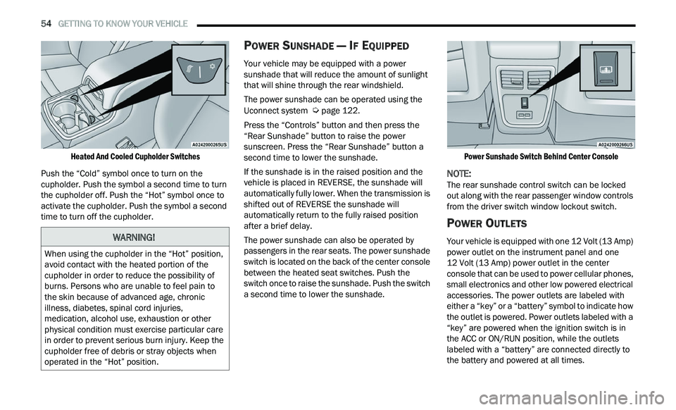
Heated And Cooled Cupholder Switches
Push the “Cold” symbol once to turn on the
cu
pholder. Push the symbol a second time to turn
the cupholder off. Push the “Hot” symbol once to
activate the cupholder. Push the symbol a second
time to turn off the cupholder.
POWER SUNSHADE — IF EQUIPPED
Your vehicle may be equipped with a power
sunshade that will reduce the amount of sunlight
that will shine through the rear windshield.
The power sunshade can be operated using the
U c
onnect system Ú page 122.
Press the “Controls” button and then press the
“ R
ear Sunshade” button to raise the power
sunscreen. Press the “Rear Sunshade” button a
second time to lower the sunshade.
If the sunshade is in the raised position and the
ve
hicle is placed in REVERSE, the sunshade will
automatically fully lower. When the transmission is
shifted out of REVERSE the sunshade will
automatically return to the fully raised position
after a brief delay.
The power sunshade can also be operated by
p a
ssengers in the rear seats. The power sunshade
switch is located on the back of the center console
between the heated seat switches. Push the
switch once to raise the sunshade. Push the switch
a second time to lower the sunshade.
Power Sunshade Switch Behind Center Console
NOTE:
The rear sunshade control switch can be locked
ou t
along with the rear passenger window controls
from the driver switch window lockout switch.
POWER OUTLETS
Your vehicle is equipped with one 12 Volt (13 Amp)
power outlet on the instrument panel and one
12 Volt (13 Amp) power outlet in the center
c on
sole that can be used to power cellular phones,
small electronics and other low powered electrical
accessories. The power outlets are labeled with
either a “key” or a “battery” symbol to indicate how
the outlet is powered. Power outlets labeled with a
“key” are powered when the ignition switch is in
the ACC or ON/RUN position, while the outlets
labeled with a “battery” are connected directly to
the battery and powered at all times.
WARNING!
When using the cupholder in the “Hot” position,
avoid contact with the heated portion of the
cupholder in order to reduce the possibility of
burns. Persons who are unable to feel pain to
the skin because of advanced age, chronic
illness, diabetes, spinal cord injuries,
medication, alcohol use, exhaustion or other
physical condition must exercise particular care
in order to prevent serious burn injury. Keep the
cupholder free of debris or stray objects when
operated in the “Hot” position.
Page 58 of 268

56 GETTING TO KNOW YOUR VEHICLE
WINDOWS
POWER WINDOW CONTROLS
The window controls on the driver's door control all
the door windows.
Power Window Switches
The passenger door windows can also be operated
b y
using the single window controls on the
passenger door trim panel. The window controls
will operate only when the ignition is in the ACC or
ON/RUN position.
NOTE:
The power window switches will remain active for
u p
to 10 minutes after the ignition is placed in the
O F
F position. Opening either front door will cancel
this feature. The timing is programmable within
Uconnect Settings
Ú page 122.
AUTOMATIC WINDOW FEATURES
Auto-Down Feature
The driver and front passenger door power window
sw
itches have an Auto-Down feature. Push the
window switch down to the second detent, release,
and the window will go down automatically.
To stop the window from going all the way down
du
ring the Auto-Down operation, pull up or push
down on the switch briefly.
CAUTION!
Many accessories that can be plugged in draw
power from the vehicle's battery even when
not in use (i.e., cellular phones, etc.). Eventu -
ally, if plugged in long enough, the vehicle's
b a
ttery will discharge sufficiently to degrade
battery life and/or prevent the engine from
starting.
Accessories that draw higher power (i.e.,
coolers, vacuum cleaners, lights, etc.) will
degrade the battery even more quickly. Only
use these intermittently and with greater
caution.
After the use of high power draw accessories
or long periods of the vehicle not being started
(with accessories still plugged in), the vehicle
must be driven a sufficient length of time to
allow the alternator to recharge the vehicle's
battery.
Power outlets are designed for accessory
plugs only. Do not hang any type of accessory
or accessory bracket from the plug. Improper
use of the power outlet can cause damage.
WARNING!
Never leave children unattended in a vehicle, and
do not let children play with power windows. Do
not leave the key fob in or near the vehicle, or in a
location accessible to children, and do not leave
the ignition of a vehicle equipped with Keyless
Enter ‘n Go™ in the ACC or ON/RUN position.
Occupants, particularly unattended children, can
become entrapped by the windows while operat -
ing the power window switches. Such entrapment
m a
y result in serious injury or death.
Page 59 of 268
GETTING TO KNOW YOUR VEHICLE 57
Auto-Up Feature With Anti-Pinch Protection
Pull the window switch up to the second detent and
th
e window will go up automatically.
To stop the window from going all the way up
du
ring the Auto-Up operation, push down on the
switch briefly.
To close the window part way, lift the window
s w
itch briefly and release it when you want the
window to stop.
If the window runs into any obstacle during
a u
to-closure, it will reverse direction and then go
back down. Remove the obstacle and use the
window switch again to close the window.
NOTE:
Any impact due to rough road conditions may
t r
igger the auto-reverse function unexpectedly
during auto-closure. If this happens, pull the switch
lightly and hold to close the window manually.
RESET AUTO-UP
Should the Auto-Up feature stop working, the
window may need to be reset. To reset Auto-Up:
1. Make sure the door is fully closed.
2
. P ull the window switch up to close the window
c
ompletely and continue to hold the switch up
for an additional two seconds after the window
is closed.
3. Push the window switch down firmly to the s
econd detent to open the window completely
and continue to hold the switch down for an
additional two seconds after the window is
fully open.
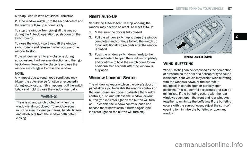
WINDOW LOCKOUT SWITCH
The window lockout switch on the driver's door trim
panel allows you to disable the window controls on
the rear passenger doors. To disable the window
controls, push and release the window lockout
button (the indicator light on the button will turn
on). To enable the window controls, push and
release the window lockout button again (the
indicator light on the button will turn off).
Window Lockout Switch
WIND BUFFETING
Wind buffeting can be described as the perception
of pressure on the ears or a helicopter-type sound
in the ears. Your vehicle may exhibit wind buffeting
with the windows down, or the sunroof (if
equipped) in certain open or partially open
positions. This is a normal occurrence and can be
minimized. If the buffeting occurs with the rear
windows open, open the front and rear windows
together to minimize the buffeting. If the buffeting
occurs with the sunroof open, adjust the sunroof
opening to minimize the buffeting or open any
window.
WARNING!
There is no anti-pinch protection when the
window is almost closed. To avoid personal
injury be sure to clear your arms, hands, fingers
and all objects from the window path before
closing.
2
Page 68 of 268
66 GETTING TO KNOW YOUR INSTRUMENT PANEL
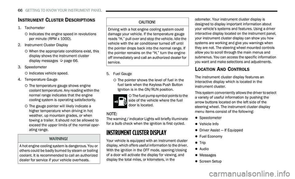
INSTRUMENT CLUSTER DESCRIPTIONS
1. Tachometer
Indicates the engine speed in revolutions
per minute (RPM x 1000).
2. Instrument Cluster Display
When the appropriate conditions exist, this
display shows the instrument cluster
display messages
Ú page 66.
3. S peedometer
Indicates vehicle speed.
4. T emperature Gauge
The temperature gauge shows engine
coolant temperature. Any reading within the
normal range indicates that the engine
cooling system is operating satisfactorily.
The gauge pointer will likely indicate a
higher temperature when driving in hot
weather, up mountain grades, or when
towing a trailer. It should not be allowed to
exceed the upper limits of the normal oper
-
ating range. 5. Fuel Gauge
The pointer shows the level of fuel in the
fuel tank when the Keyless Push Button
Ignition is in the ON/RUN position.
The fuel pump symbol points to the
side of the vehicle where the fuel
d oor
is located.
NOTE:
The warning / indicator Lights will briefly illuminate
f or
a bulb check when the ignition is first cycled.
INSTRUMENT CLUSTER DISPLAY
Your vehicle is equipped with an instrument cluster
display, which offers useful information to the driver.
With the ignition in the OFF mode, opening/closing
of a door will activate the display for viewing, and
display the total miles, or kilometers, in the odometer. Your instrument cluster display is
designed to display important information about
your vehicle’s systems and features. Using a driver
interactive display located on the instrument panel,
your instrument cluster display can show you how
systems are working and give you warnings when
they are not. The steering wheel mounted controls
allow you to scroll through the main menus and
submenus. You can access the specific information
you want and make selections and adjustments.
LOCATION AND CONTROLS
The instrument cluster display features an
interactive display which is located in the
instrument cluster.
This system conveniently allows the driver to select
a
variety of useful information by pushing the
arrow buttons located on the left side of the
steering wheel. The instrument cluster display
menu items consist of the following:
Speedometer
Vehicle Info
Driver Assist — If Equipped
Fuel Economy
Trip
Audio
Messages
Screen Setup
WARNING!
A hot engine cooling system is dangerous. You or
others could be badly burned by steam or boiling
coolant. It is recommended to call an authorized
dealer for service if your vehicle overheats.
CAUTION!
Driving with a hot engine cooling system could
damage your vehicle. If the temperature gauge
reads “H,” pull over and stop the vehicle. Idle the
vehicle with the air conditioner turned off until
the pointer drops back into the normal range. If
the pointer remains on the “H,” turn the engine
off immediately and call an authorized dealer for
service.
Page 73 of 268
GETTING TO KNOW YOUR INSTRUMENT PANEL 71
NOTE:
The charging system is independent from load
reduction. The charging system performs a diag
-
nostic on the charging system continuously.
If the Battery Charge Warning Light is on it may
indicate a problem with the charging system
Ú page 73.
The electrical loads that may be switched off (if
e q
uipped), and vehicle functions which can be
affected by load reduction:
Heated Seat/Vented Seats/Heated Wheel —
If Equipped
Heated/Cooled Cup Holders — If Equipped
Rear Defroster And Heated Mirrors
HVAC System
115 Volts AC Power Inverter System
Audio and Telematics System
Loss of the battery charge may indicate one or
m or
e of the following conditions:
The charging system cannot deliver enough
electrical power to the vehicle system because
the electrical loads are larger than the capability
of the charging system. The charging system is
still functioning properly.
Turning on all possible vehicle electrical loads
(e.g. HVAC to max settings, exterior and interior
lights, overloaded power outlets +12 Volts, 115 Volts AC, USB ports) during certain driving
c
on
ditions (city driving, towing, frequent stop -
ping).
Installing options like additional lights, upfitter
electrical accessories, audio systems, alarms
and similar devices.
Unusual driving cycles (short trips separated by
long parking periods).
The vehicle was parked for an extended period
of time (weeks, months).
The battery was recently replaced and was not
charged completely.
The battery was discharged by an electrical load
left on when the vehicle was parked.
The battery was used for an extended period
with the engine not running to supply radio,
lights, chargers, +12 Volt portable appliances
like vacuum cleaners, game consoles and
similar devices.
What to do when an electrical load reduction
a c
tion message is present (“Battery Saver On” or
“Battery Saver Mode”)
During a trip:
Reduce power to unnecessary loads if possible:
Turn off redundant lights (interior or exte -
rior)
Check what may be plugged in to power
outlets +12 Volts, 115 Volts AC, USB ports
Check HVAC settings (blower, temperature)
Check the audio settings (volume)
After a trip:
Check if any aftermarket equipment was
installed (additional lights, upfitter electrical
accessories, audio systems, alarms) and review
specifications if any (load and Ignition Off Draw
currents).
Evaluate the latest driving cycles (distance,
driving time and parking time).
The vehicle should have service performed if
the message is still present during consecutive
trips and the evaluation of the vehicle and
driving pattern did not help to identify the cause.
PROGRAMMABLE FEATURES
The instrument cluster display can be used to view
or change the following settings. Push the up
or
down arrow button to scroll through the main
menus, then push the ri
ght arrow button to
scroll through the submenus of each menu item.
P u
sh the left arrow button to scroll back to a
previous menu or submenu.
WARNING LIGHTS AND MESSAGES
The warning/indicator lights will illuminate in the
instrument panel together with a dedicated
message and/or acoustic signal when applicable.
These indications are indicative and precautionary
3