2021 CHRYSLER 300 warning light
[x] Cancel search: warning lightPage 87 of 268
STARTING AND OPERATING 85
(Continued)
(Continued)
(Continued)
When the parking brake is applied with the ignition
switch in the ON/RUN position, the Brake Warning
Light in the instrument cluster will illuminate.
NOTE:
When the parking brake is applied and the trans -
mission is placed in gear, the Brake Warning Light
w i
ll flash. If vehicle speed is detected, a chime will
sound to alert the driver. Fully release the parking
brake before attempting to move the vehicle.
This light only shows that the parking brake is
applied. It does not show the degree of brake
application.
When parking on a hill, it is important to turn the
f r
ont wheels toward the curb on a downhill grade
and away from the curb on an uphill grade. Apply
the parking brake before placing the gear selector
in PARK, otherwise the load on the transmission
locking mechanism may make it difficult to move
the gear selector out of PARK. The parking brake
should always be applied whenever the driver is
not in the vehicle.
AUTOMATIC TRANSMISSION
NOTE:
You must press and hold the brake pedal while
s h
ifting out of PARK.
WARNING!
Never use the PARK position as a substitute
for the parking brake. Always apply the
parking brake fully when parked to guard
against vehicle movement and possible injury
or damage.
When exiting the vehicle, always remove the
key fob from the ignition and lock your vehicle.
Never leave children alone in a vehicle, or with
access to an unlocked vehicle. Allowing chil -
dren to be in a vehicle unattended is
d a
ngerous for a number of reasons. A child or
others could be seriously or fatally injured.
Children should be warned not to touch the
parking brake, brake pedal or the gear
selector.
When exiting the vehicle, always make sure
the keyless ignition node is in the OFF mode,
remove the key fob from the vehicle and lock
the vehicle.
Do not leave the key fob in or near the vehicle
or in a location accessible to children, and do
not leave the ignition of a vehicle equipped
with Keyless Enter ‘n Go™ in the ACC or ON/
RUN mode. A child could operate power
windows, other controls, or move the vehicle.
Be sure the parking brake is fully disengaged
before driving; failure to do so can lead to
brake failure and a collision.
WARNING!
Always fully apply the parking brake when
leaving your vehicle, or it may roll and cause
damage or injury. Also be certain to leave the
transmission in PARK. Failure to do so may
allow the vehicle to roll and cause damage or
injury.
CAUTION!
If the Brake Warning Light remains on with the
parking brake released, a brake system
malfunction is indicated. Have the brake system
serviced by an authorized dealer immediately.
WARNING!
Never use the PARK position as a substitute
for the parking brake. Always apply the
parking brake fully when exiting the vehicle to
guard against vehicle movement and possible
injury or damage.
WARNING!
4
Page 94 of 268
92 STARTING AND OPERATING
FUEL SAVER TECHNOLOGY 5.7L ONLY —
IF EQUIPPED
This feature offers improved fuel economy by
shutting off four of the engine's eight cylinders
during light load and cruise conditions. The system
is automatic with no driver inputs or additional
driving skills required.
NOTE:
This system may take some time to return to full
f u
nctionality after a battery disconnect.
POWER STEERING
The Electric Power Steering system will give you
good vehicle response and increased ease of
maneuverability in tight spaces. The system will
vary its assist to provide light efforts while parking
and good feel while driving. If the electric steering
system experiences a fault that prevents it from
providing assist, you will still have the ability to
steer the vehicle manually. Alternate electric power steering efforts can be
s
e
lected through the Uconnect system
Ú page 122.
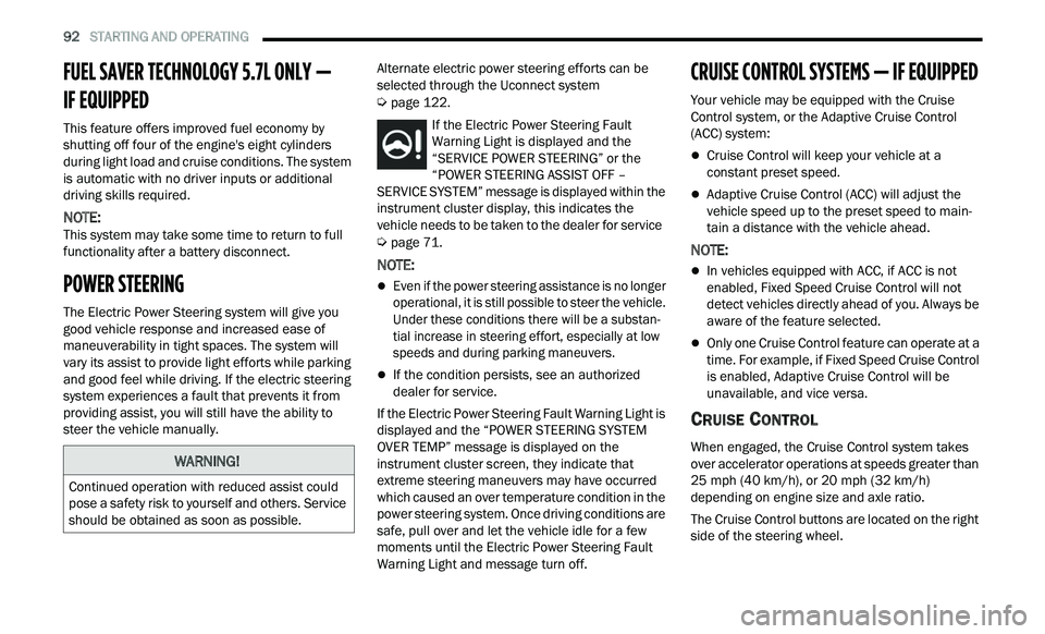
If the Electric Power Steering Fault
Warning Light is displayed and the
“ S
ERVICE POWER STEERING” or the
“POWER STEERING ASSIST OFF –
SERVICE SYSTEM” message is displayed within the
instrument cluster display, this indicates the
vehicle needs to be taken to the dealer for service
Ú page 71.
NOTE:
Even if the power steering assistance is no longer
operational, it is still possible to steer the vehicle.
Under these conditions there will be a substan
-
tial increase in steering effort, especially at low
s p
eeds and during parking maneuvers.
If the condition persists, see an authorized
dealer for service.
If the Electric Power Steering Fault Warning Light is
di
splayed and the “POWER STEERING SYSTEM
OVER TEMP” message is displayed on the
instrument cluster screen, they indicate that
extreme steering maneuvers may have occurred
which caused an over temperature condition in the
power steering system. Once driving conditions are
safe, pull over and let the vehicle idle for a few
moments until the Electric Power Steering Fault
Warning Light and message turn off.
CRUISE CONTROL SYSTEMS — IF EQUIPPED
Your vehicle may be equipped with the Cruise
Control system, or the Adaptive Cruise Control
(ACC) system:
Cruise Control will keep your vehicle at a
constant preset speed.
Adaptive Cruise Control (ACC) will adjust the
vehicle speed up to the preset speed to main -
tain a distance with the vehicle ahead.
NOTE:
In vehicles equipped with ACC, if ACC is not
enabled, Fixed Speed Cruise Control will not
detect vehicles directly ahead of you. Always be
aware of the feature selected.
Only one Cruise Control feature can operate at a
time. For example, if Fixed Speed Cruise Control
is enabled, Adaptive Cruise Control will be
unavailable, and vice versa.
CRUISE CONTROL
When engaged, the Cruise Control system takes
over accelerator operations at speeds greater than
25 mph (40 km/h), or 20 mph (32 km/h)
de
pending on engine size and axle ratio.
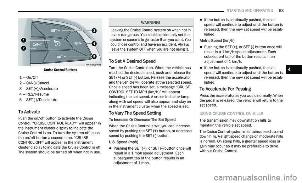
The Cruise Control buttons are located on the right
si
de of the steering wheel.
WARNING!
Continued operation with reduced assist could
pose a safety risk to yourself and others. Service
should be obtained as soon as possible.
Page 95 of 268
STARTING AND OPERATING 93
Cruise Control Buttons
To Activate
Push the on/off button to activate the Cruise
Control. “CRUISE CONTROL READY” will appear in
the instrument cluster display to indicate the
Cruise Control is on. To turn the system off, push
the on/off button a second time. “CRUISE
CONTROL OFF” will appear in the instrument
cluster display to indicate the Cruise Control is off.
The system should be turned off when not in use.
To Set A Desired Speed
Turn the Cruise Control on. When the vehicle has
reached the desired speed, push and release the
SET (+) or SET (-) button. Release the accelerator
and the vehicle will operate at the selected speed.
Once a speed has been set, a message “CRUISE
CONTROL SET TO MPH (km/h)” will appear
indicating the set speed. A cruise indicator lamp,
along with set speed will also appear and stay on
in the instrument cluster when the speed is set.
To Vary The Speed Setting
To Increase Or Decrease The Set Speed
When the Cruise Control is set, you can increase
sp
eed by pushing the SET (+) button, or decrease
speed by pushing the SET (-) button.
U.S. Speed (mph)
Pushing the SET (+) , or SET (-) button once will
result in a 1 mph speed adjustment. Each
s u
bsequent tap of the button results in an
adjustment of 1 mph.
If the button is continually pushed, the set
speed will continue to adjust until the button is
released, then the new set speed will be estab -
lished.
Metric Speed (km/h)
Pushing the SET (+), or SET (-) button once will
result in a 1 km/h speed adjustment. Each
s u
bsequent tap of the button results in an
adjustment of 1 km/h.
If the button is continually pushed, the set
speed will continue to adjust until the button is
released, then the new set speed will be estab -
lished.
To Accelerate For Passing
Press the accelerator as you would normally. When
the pedal is released, the vehicle will return to the
set speed.
USING CRUISE CONTROL ON HILLS
The transmission may downshift on hills to
maintain the vehicle set speed.
The Cruise Control system maintains speed up and
dow
n hills. A slight speed change on moderate hills
is normal. On steep hills, a greater speed loss or
gain may occur so it may be preferable to drive
without Cruise Control.
1 — On/Off
2 — CANC/Cancel
3 — SET (+)/Accelerate
4 — RES/Resume
5 — SET (-)/Decelerate
WARNING!
Leaving the Cruise Control system on when not in
use is dangerous. You could accidentally set the
system or cause it to go faster than you want. You
could lose control and have an accident. Always
leave the system OFF when you are not using it.
4
Page 96 of 268

94 STARTING AND OPERATING
(Continued)
To Resume Speed
To resume a previously set speed, push the RES
button and release. Resume can be used at any
speed above 20 mph (32 km/h).
To Deactivate
A tap on the brake pedal, pushing the CANC button,
or normal brake pressure will deactivate the Cruise
Control system without erasing the set speed from
memory.
The following conditions will also deactivate the
Cr
uise Control without erasing the set speed from
memory:
Vehicle parking brake is applied
Stability event occurs
Gear selector is moved out of DRIVE
Engine overspeed occurs Pushing the on/off button or placing the ignition in
t
h
e OFF position erases the set speed from
memory.
ADAPTIVE CRUISE CONTROL (ACC)
Adaptive Cruise Control (ACC) increases the driving
convenience provided by Cruise Control while
traveling on highways and major roadways.
However, it is not a safety system and not designed
to prevent collisions. The Cruise Control function
performs differently
Ú page 92.
ACC will allow you to keep Cruise Control engaged
i n
light to moderate traffic conditions without the
constant need to reset your Cruise Control. ACC
utilizes a radar sensor and a forward facing
camera designed to detect a vehicle directly ahead
of you.
NOTE:
If the ACC sensor detects a vehicle ahead, ACC
will apply limited braking or acceleration (not to
exceed the original set speed) automatically to
maintain a preset following distance, while
matching the speed of the vehicle ahead.
Any chassis/suspension or tire size modifica -
tions to the vehicle will affect the performance
of
the Adaptive Cruise Control and Forward Colli -
sion Warning systems.
Fixed Speed Cruise Control (ACC not enabled)
will not detect vehicles directly ahead of you.
Always be aware of the feature selected
Ú page 254.
WARNING!
Cruise Control can be dangerous where the
system cannot maintain a constant speed. Your
vehicle could go too fast for the conditions, and
you could lose control and have an accident. Do
not use Cruise Control in heavy traffic or on
roads that are winding, icy, snow-covered or
slippery.
WARNING!
Adaptive Cruise Control (ACC) is a conve -
nience system. It is not a substitute for active
d r
iver involvement. It is always the driver’s
responsibility to be attentive of road, traffic,
and weather conditions, vehicle speed,
distance to the vehicle ahead; and, most
importantly, brake operation to ensure safe
operation of the vehicle under all road condi -
tions. Your complete attention is always
r e
quired while driving to maintain safe control
of your vehicle. Failure to follow these warn -
ings can result in a collision and death or
s e
rious personal injury.
The ACC system:
Does not react to pedestrians, oncoming
vehicles, and stationary objects (e.g., a
stopped vehicle in a traffic jam or a
disabled vehicle).
Cannot take street, traffic, and weather
conditions into account, and may be
limited upon adverse sight distance condi -
tions.
Page 100 of 268

98 STARTING AND OPERATING
When ACC Is Active:
NOTE:
When you use the SET (-) button to decelerate, if
the engine’s braking power does not slow the
vehicle sufficiently to reach the set speed, the
brake system will automatically slow the
vehicle.
The ACC system applies the brake down to a full
stop when following the vehicle in front. If your
vehicle follows the vehicle in front to a standstill,
your vehicle will release the brakes two seconds
after coming to a full stop.
The ACC will bring the vehicle to a complete stop
while following a vehicle in front and hold the
vehicle for two seconds in the stop position. If
the vehicle in front does not start moving within
two seconds, the ACC system will display a
message that the system will release the brakes
and that the brakes must be applied manually.
An audible chime will sound when the brakes
are released.
The ACC system maintains set speed when
driving uphill and downhill. However, a slight
speed change on moderate hills is normal. In
addition, downshifting may occur while climbing
uphill or descending downhill. This is normal
operation and necessary to maintain set speed.
When driving uphill and downhill, the ACC
system will cancel if the braking temperature
exceeds normal range (overheated).
Setting The Following Distance In ACC
The specified following distance for ACC can be set
by varying the distance setting between four bars
(longest), three bars (long), two bars (medium) and
one bar (short). Using this distance setting and the
vehicle speed, ACC calculates and sets the
distance to the vehicle ahead. This distance
setting displays in the instrument cluster display.
Distance Settings
To increase the distance setting, push the
D i
stance Setting Increase button and release.
Each time the button is pushed, the distance
setting increases by one bar (longer). To decrease the distance setting, push the
D
i
stance Setting Decrease button and release.
Each time the button is pushed, the distance
setting decreases by one bar (shorter).
If there is no vehicle ahead, the vehicle will
ma
intain the set speed. If a slower moving vehicle
is detected in the same lane, the instrument
cluster display will show the ACC Set With Target
Detected Indicator Light, and the system will adjust
the vehicle speed automatically to maintain the
distance setting, regardless of the set speed.
The vehicle will then maintain the set distance
u n
til:
The vehicle ahead accelerates to a speed above
the set speed.
The vehicle ahead moves out of your lane or
view of the sensor.
The distance setting is changed.
The system disengages Ú page 96.
The maximum braking applied by ACC is limited;
h ow
ever, the driver can always apply the brakes
manually, if necessary.
NOTE:
The brake lights will illuminate whenever the ACC
s y
stem applies the brakes.
A Proximity Warning will alert the driver if ACC
pr
edicts that its maximum braking level is not
sufficient to maintain the set distance. If this
1 — Longest Distance Setting (Four Bars)
2 — Medium Distance Setting (Two Bars)
3 — Long Distance Setting (Three Bars)
4 — Short Distance Setting (One Bar)
Page 114 of 268
112 STARTING AND OPERATING
(Continued)
NOTE:
In certain cold conditions, ice may prevent the fuel
d oor
from opening. If this occurs, lightly push on
the fuel door to break the ice buildup and
re-release the fuel door using the inside release
button. Do not pry on the door.
3. T here is no fuel filler cap. Two flapper doors
i
nside the pipe seal the system.
4. Insert the fuel nozzle fully into the filler pipe – t
he nozzle opens and holds the flapper doors
while refueling.
5. F ill the vehicle with fuel – when the fuel nozzle
“
clicks” or shuts off the fuel tank is full.
6. Maintain nozzle in filler for five seconds to a
llow nozzle to drain.
7. Remove the fuel nozzle and close the fuel d
oor.
NOTE:
A funnel is provided (located in the trunk in the
s p
are tire area) to open the flapper doors to allow
for emergency refueling with a gas can.
EMERGENCY FUEL FILLER DOOR
R
ELEASE
If you are unable to open the fuel filler door, use
the fuel filler door emergency release located in
the trunk.
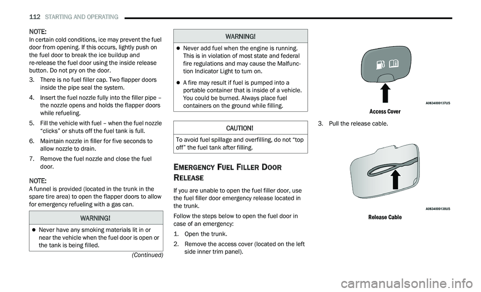
Follow the steps below to open the fuel door in
c a
se of an emergency:
1. Open the trunk.
2
. R emove the access cover (located on the left
s
ide inner trim panel).
Access Cover
3. P ull the release cable.
R
elease Cable
WARNING!
Never have any smoking materials lit in or
near the vehicle when the fuel door is open or
the tank is being filled.
Never add fuel when the engine is running.
This is in violation of most state and federal
fire regulations and may cause the Malfunc -
tion Indicator Light to turn on.
A fire may result if fuel is pumped into a
portable container that is inside of a vehicle.
You could be burned. Always place fuel
containers on the ground while filling.
CAUTION!
To avoid fuel spillage and overfilling, do not “top
off” the fuel tank after filling.
WARNING!
Page 117 of 268
STARTING AND OPERATING 115
Weight-Distributing Hitch
A weight-distributing system works by applying
leverage through spring (load) bars. They are
typically used for heavier loads to distribute trailer
tongue weight to the tow vehicle's front axle and
the trailer axle(s). When used in accordance with
the manufacturer's directions, it provides for a
more level ride, offering more consistent steering
and brake control thereby enhancing towing
safety. The addition of a friction/hydraulic sway
control also dampens sway caused by traffic and
crosswinds and contributes positively to tow
vehicle and trailer stability. Trailer sway control and
a weight distributing (load equalizing) hitch are
recommended for heavier Tongue Weights (TW) and may be required depending on vehicle and
trailer configuration/loading to comply with Gross
Axle Weight Rating (GAWR) requirements.
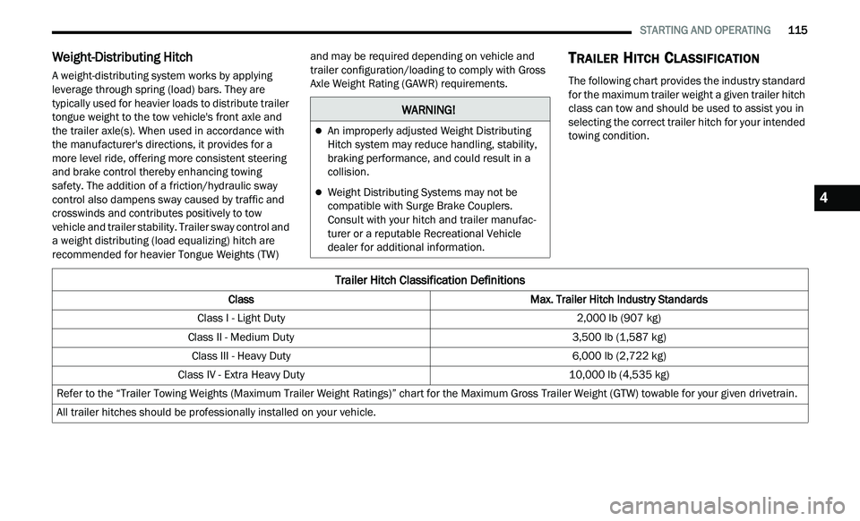
TRAILER HITCH CLASSIFICATION
The following chart provides the industry standard
for the maximum trailer weight a given trailer hitch
class can tow and should be used to assist you in
selecting the correct trailer hitch for your intended
towing condition.
WARNING!
An improperly adjusted Weight Distributing
Hitch system may reduce handling, stability,
braking performance, and could result in a
collision.
Weight Distributing Systems may not be
compatible with Surge Brake Couplers.
Consult with your hitch and trailer manufac
-
turer or a reputable Recreational Vehicle
d e
aler for additional information.
Trailer Hitch Classification Definitions
Class Max. Trailer Hitch Industry Standards
Class I - Light Duty 2,000 lb (907 kg)
Class II - Medium Duty 3,500 lb (1,587 kg)
Class III - Heavy Duty 6,000 lb (2,722 kg)
Class IV - Extra Heavy Duty 10,000 lb (4,535 kg)
Refer to the “Trailer Towing Weights (Maximum Trailer Weight Ratings)” chart for the Maximum Gross Trailer Weight (GTW) towable for your given drivetrain.
All trailer hitches should be professionally installed on your vehicle.
4
Page 120 of 268

118 STARTING AND OPERATING
Towing Requirements — Trailer Lights And
Wiring
Whenever you pull a trailer, regardless of the trailer
size, stop lights and turn signals on the trailer are
required for motoring safety.
The Trailer Tow Package may include a four- and
se
ven-pin wiring harness. Use a factory approved
trailer harness and connector.
NOTE:
Do not cut or splice wiring into the vehicle’s wiring
h a
rness. The electrical connections are all complete to the
v
e
hicle but you must mate the harness to a trailer
connector. Refer to the following illustrations.
NOTE:
Disconnect trailer wiring connector from the
vehicle before launching a boat (or any other
device plugged into vehicle’s electrical connect)
into water.
Be sure to reconnect after clear from water
area.
Four-Pin Connector Seven-Pin Connector
TOWING TIPS
Before setting out on a trip, practice turning,
stopping, and backing up the trailer in an area
located away from heavy traffic.
Towing any trailer will increase your stopping
distance. When towing, you should allow for
additional space between your vehicle and the
vehicle in front of you. Failure to do so could
result in an accident.
CAUTION!
If the trailer weighs more than 1,000 lb (453 kg)
loaded, it should have its own brakes and they
should be of adequate capacity. Failure to do
this could lead to accelerated brake lining wear,
higher brake pedal effort, and longer stopping
distances.
WARNING!
1 — Ground
2 — Park
3 — Left Stop/Turn
4 — Right Stop/Turn
1 — Backup Lamps
2 — Running Lamps
3 — Left Stop/Turn
4 — Ground
5 — Battery
6 — Right Stop/Turn
7 — Electric Brakes