2021 CHRYSLER 300 instrument panel
[x] Cancel search: instrument panelPage 49 of 268
GETTING TO KNOW YOUR VEHICLE 47
The Rain Sensing system has protection features
for the wiper blades and arms, and will not operate
under the following conditions:
Low Ambient Temperature — When the ignition
is first placed in the ON position, the Rain
Sensing system will not operate until the wiper
switch is moved, vehicle speed is greater than
3 mph (5 km/h), or the outside temperature is
gr
eater than 32°F (0°C).
Transmission In NEUTRAL Position — When the
ignition is ON, and the automatic transmission
is in the NEUTRAL position, the Rain Sensing
system will not operate until the wiper switch is
moved, vehicle speed is greater than 3 mph
(5
km/h), or the gear selector is moved out of
t h
e NEUTRAL position.
Remote Start Mode Inhibit — On vehicles
equipped with a Remote Start system, Rain
Sensing wipers are not operational when the
vehicle is in Remote Start mode.
CLIMATE CONTROLS
The Climate Control system allows you to regulate
the temperature, air flow, and direction of air
circulating throughout the vehicle. The controls are
located on the touchscreen (if equipped) and on
the instrument panel below the radio.
AUTOMATIC CLIMATE CONTROL
D
ESCRIPTIONS AND FUNCTIONS
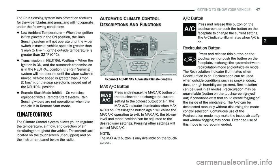
Uconnect 4C/4C NAV Automatic Climate Controls
MAX A/C Button
Press and release the MAX A/C button on
the touchscreen to change the current
s e
tting to the coldest output of air. The
MAX A/C indicator illuminates when MAX
A/C is on. Pressing the button again will cause the
MAX A/C operation to exit. In MAX A/C, the blower
level and mode position can be adjusted to the
desired user settings. Pressing other settings will
cancel MAX A/C.
NOTE:
The MAX A/C button is only available on the touch -
screen.
A/C Button
Press and release this button on the
touchscreen, or push the button on the
f a
ceplate to change the current setting.
The A/C indicator illuminates when A/C is
on.
Recirculation Button
Press and release this button on the
touchscreen, or push the button on the
f a
ceplate, to change the system between
recirculation mode and outside air mode.
The Recirculation indicator illuminates when
Recirculation is on. Recirculation can be used
when outside conditions such as smoke, odors,
dust, or high humidity are present. Recirculation
can be used in all modes. Recirculation may be
unavailable (button on the touchscreen greyed
out) if conditions exist that could create fogging on
the inside of the windshield. The A/C can be
deselected manually without disturbing the mode
control selection. Continuous use of the
Recirculation mode may make the inside air stuffy
and window fogging may occur. Extended use of
this mode is not recommended.
2
Page 51 of 268
GETTING TO KNOW YOUR VEHICLE 49
The speeds can be selected using either the
blower control knob on the faceplate or the
buttons on the touchscreen.
Faceplate
The blower speed increases as you turn the blower
c
on
trol knob clockwise from the lowest blower
setting. The blower speed decreases as you turn
the blower control knob counterclockwise.
Touchscreen
Use the small blower icon to reduce the blower
s e
tting and the large blower icon to increase the
blower setting. Blower can also be selected by
pressing the blower bar area between the icons.
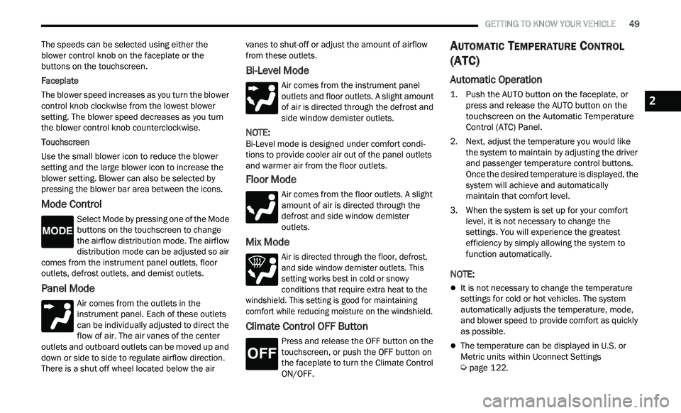
Mode Control
Select Mode by pressing one of the Mode
buttons on the touchscreen to change
t h
e airflow distribution mode. The airflow
distribution mode can be adjusted so air
comes from the instrument panel outlets, floor
outlets, defrost outlets, and demist outlets.
Panel Mode
Air comes from the outlets in the
instrument panel. Each of these outlets
c a
n be individually adjusted to direct the
flow of air. The air vanes of the center
outlets and outboard outlets can be moved up and
down or side to side to regulate airflow direction.
There is a shut off wheel located below the air vanes to shut-off or adjust the amount of airflow
from these outlets.
Bi-Level Mode
Air comes from the instrument panel
outlets and floor outlets. A slight amount
of
air is directed through the defrost and
side window demister outlets.
NOTE:
Bi-Level mode is designed under comfort condi -
tions to provide cooler air out of the panel outlets
a n
d warmer air from the floor outlets.
Floor Mode
Air comes from the floor outlets. A slight
amount of air is directed through the
de
frost and side window demister
outlets.
Mix Mode
Air is directed through the floor, defrost,
and side window demister outlets. This
s e
tting works best in cold or snowy
conditions that require extra heat to the
windshield. This setting is good for maintaining
comfort while reducing moisture on the windshield.
Climate Control OFF Button
Press and release the OFF button on the
touchscreen, or push the OFF button on
t h
e faceplate to turn the Climate Control
ON/OFF.
AUTOMATIC TEMPERATURE CONTROL
(ATC)
Automatic Operation
1. Push the AUTO button on the faceplate, or
press and release the AUTO button on the
touchscreen on the Automatic Temperature
Control (ATC) Panel.
2. Next, adjust the temperature you would like t
he system to maintain by adjusting the driver
and passenger temperature control buttons.
Once the desired temperature is displayed, the
system will achieve and automatically
maintain that comfort level.
3. When the system is set up for your comfort l
evel, it is not necessary to change the
settings. You will experience the greatest
efficiency by simply allowing the system to
function automatically.
NOTE:
It is not necessary to change the temperature
settings for cold or hot vehicles. The system
automatically adjusts the temperature, mode,
and blower speed to provide comfort as quickly
as possible.
The temperature can be displayed in U.S. or
Metric units within Uconnect Settings
Ú page 122.
2
Page 53 of 268
GETTING TO KNOW YOUR VEHICLE 51
Operating Tips ChartINTERIOR STORAGE AND EQUIPMENT
STORAGE
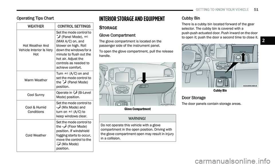
Glove Compartment
The glove compartment is located on the
passenger side of the instrument panel.
To open the glove compartment, pull the release
ha
ndle.
Glove Compartment
Cubby Bin
There is a cubby bin located forward of the gear
selector. The cubby bin is covered with a
push-push actuated door. Push inward on the door
to open it; push the door a second time to close it.
Cubby Bin
Door Storage
The door panels contain storage areas.
WEATHERCONTROL SETTINGS
Hot Weather And
Vehicle Interior Is Very Hot Set the mode control to
(Panel Mode),
(MAX A/C) on, and
b l
ower on high. Roll
down the windows for a
minute to flush out the
hot air. Adjust the
controls as needed to
achieve comfort.
Warm Weather Turn
(A/C) on and
set the mode control to
t h
e (Panel Mode)
position.
Cool Sunny Operate in
(Bi-Level
Mode) position.
Cool & Humid Con
ditions Set the mode control to
(Mix Mode) and
turn on (A/C) to
keep windows clear.
Cold Weather Set the mode control to
t
h
e (Floor Mode)
position. If windshield
f og
ging starts to occur,
move the control to the
(Mix Mode)
position.
WARNING!
Do not operate this vehicle with a glove
compartment in the open position. Driving with
the glove compartment open may result in injury
in a collision.
2
Page 56 of 268
54 GETTING TO KNOW YOUR VEHICLE
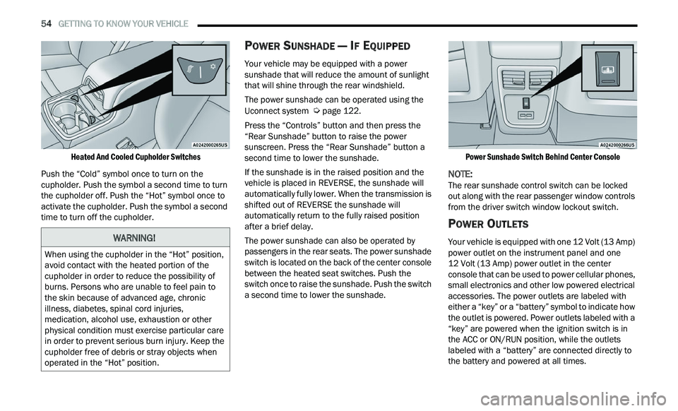
Heated And Cooled Cupholder Switches
Push the “Cold” symbol once to turn on the
cu
pholder. Push the symbol a second time to turn
the cupholder off. Push the “Hot” symbol once to
activate the cupholder. Push the symbol a second
time to turn off the cupholder.
POWER SUNSHADE — IF EQUIPPED
Your vehicle may be equipped with a power
sunshade that will reduce the amount of sunlight
that will shine through the rear windshield.
The power sunshade can be operated using the
U c
onnect system Ú page 122.
Press the “Controls” button and then press the
“ R
ear Sunshade” button to raise the power
sunscreen. Press the “Rear Sunshade” button a
second time to lower the sunshade.
If the sunshade is in the raised position and the
ve
hicle is placed in REVERSE, the sunshade will
automatically fully lower. When the transmission is
shifted out of REVERSE the sunshade will
automatically return to the fully raised position
after a brief delay.
The power sunshade can also be operated by
p a
ssengers in the rear seats. The power sunshade
switch is located on the back of the center console
between the heated seat switches. Push the
switch once to raise the sunshade. Push the switch
a second time to lower the sunshade.
Power Sunshade Switch Behind Center Console
NOTE:
The rear sunshade control switch can be locked
ou t
along with the rear passenger window controls
from the driver switch window lockout switch.
POWER OUTLETS
Your vehicle is equipped with one 12 Volt (13 Amp)
power outlet on the instrument panel and one
12 Volt (13 Amp) power outlet in the center
c on
sole that can be used to power cellular phones,
small electronics and other low powered electrical
accessories. The power outlets are labeled with
either a “key” or a “battery” symbol to indicate how
the outlet is powered. Power outlets labeled with a
“key” are powered when the ignition switch is in
the ACC or ON/RUN position, while the outlets
labeled with a “battery” are connected directly to
the battery and powered at all times.
WARNING!
When using the cupholder in the “Hot” position,
avoid contact with the heated portion of the
cupholder in order to reduce the possibility of
burns. Persons who are unable to feel pain to
the skin because of advanced age, chronic
illness, diabetes, spinal cord injuries,
medication, alcohol use, exhaustion or other
physical condition must exercise particular care
in order to prevent serious burn injury. Keep the
cupholder free of debris or stray objects when
operated in the “Hot” position.
Page 57 of 268
GETTING TO KNOW YOUR VEHICLE 55
NOTE:
All accessories connected to the “battery” powered
ou t
lets should be removed or turned off when the
vehicle is not in use to protect the battery against
discharge.
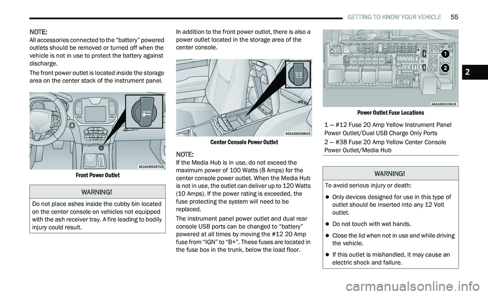
The front power outlet is located inside the storage
ar
ea on the center stack of the instrument panel.
Front Power Outlet
In addition to the front power outlet, there is also a
p
ow
er outlet located in the storage area of the
center console.
Center Console Power Outlet
NOTE:
If the Media Hub is in use, do not exceed the
m a
ximum power of 100 Watts (8 Amps) for the
center console power outlet. When the Media Hub
is not in use, the outlet can deliver up to 120 Watts
(10 Amps). If the power rating is exceeded, the
fuse protecting the system will need to be
replaced.
The instrument panel power outlet and dual rear
c on
sole USB ports can be changed to “battery”
powered at all times by moving the #12 20 Amp
fuse from “IGN” to “B+”. These fuses are located in
the fuse box in the trunk, below the load floor.
Power Outlet Fuse Locations
WARNING!
Do not place ashes inside the cubby bin located
on the center console on vehicles not equipped
with the ash receiver tray. A fire leading to bodily
injury could result.
1 — #12 Fuse 20 Amp Yellow Instrument Panel
Power Outlet/Dual USB Charge Only Ports
2 — #38 Fuse 20 Amp Yellow Center Console
Power Outlet/Media Hub
WARNING!
To avoid serious injury or death:
Only devices designed for use in this type of
outlet should be inserted into any 12 Volt
outlet.
Do not touch with wet hands.
Close the lid when not in use and while driving
the vehicle.
If this outlet is mishandled, it may cause an
electric shock and failure.
2
Page 61 of 268
GETTING TO KNOW YOUR VEHICLE 59
VENTING SUNROOF
Push and release the "Vent" button within one-half
second and the sunroof will open to the vent
position. This is called “Express Vent”, and it will
occur regardless of sunroof position. During
Express Vent operation, any movement of the
switch will stop the sunroof.
NOTE:
If the sunshade is in the closed position when the
v e
nt switch is pushed, the sunshade will automati -
cally cycle to the halfway open position prior to the
s u
nroof opening to the Vent position.
OPENING AND CLOSING THE POWER
S
HADE
Express Open/Close
Push the shade switch rearward and release it
w i
thin one-half second and the shade will
automatically open to the halfway position and
stop automatically. Push the switch again to fully
open the shade.
Push the switch forward and release it within
on e
-half second and the shade will close
automatically from any position.
During Express Open or Express Close operation,
a n
y other movement of the shade switch will stop
the shade. Manual Open/Close
To open the shade, push and hold the switch
r
e
arward. The shade will open and stop
automatically at the half-open position. Push and
hold the switch again and the shade will fully open.
To close the shade, push and hold the switch in the
for
ward position.
Any release of the switch will stop the movement
an
d the shade will remain in a partially closed
condition until the switch is pushed again.
SUNROOF MAINTENANCE
Use only a non-abrasive cleaner and a soft cloth to
clean the glass panel. Periodically check for and
clear out any debris that may have collected in the
tracks.
IGNITION OFF OPERATION
The power sunroof switch can remain active in
Accessory Delay for up to approximately
10 minutes after the vehicle’s ignition is placed to
th
e OFF position. Opening either front door will
cancel this feature.
This feature is programmable using the Uconnect
s y
stem Ú page 122.
HOOD
OPENING THE HOOD
To open the hood, two latches must be released.
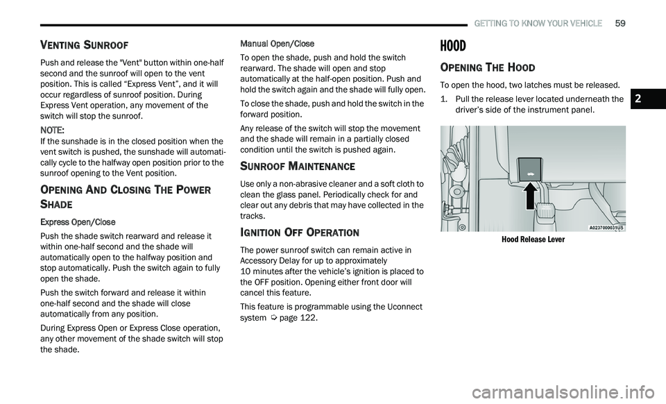
1. P ull the release lever located underneath the
d
river’s side of the instrument panel.
Hood Release Lever
2
Page 62 of 268
60 GETTING TO KNOW YOUR VEHICLE
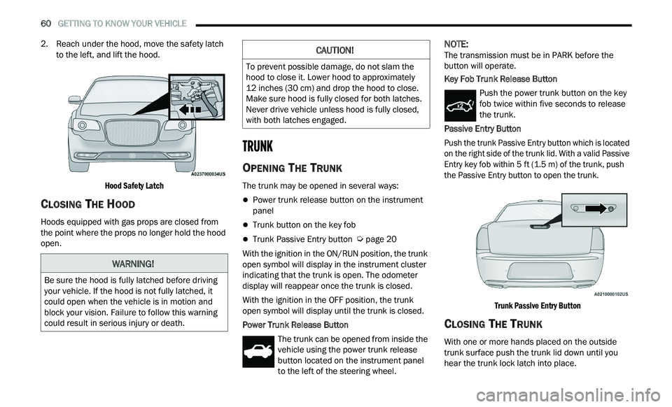
2. Reach under the hood, move the safety latch
to the left, and lift the hood.
Hood Safety Latch
CLOSING THE HOOD
Hoods equipped with gas props are closed from
the point where the props no longer hold the hood
open.
TRUNK
OPENING THE TRUNK
The trunk may be opened in several ways:
Power trunk release button on the instrument
panel
Trunk button on the key fob
Trunk Passive Entry button Ú page 20
With the ignition in the ON/RUN position, the trunk
op e
n symbol will display in the instrument cluster
indicating that the trunk is open. The odometer
display will reappear once the trunk is closed.
With the ignition in the OFF position, the trunk
ope
n symbol will display until the trunk is closed.
Power Trunk Release Button The trunk can be opened from inside the
vehicle using the power trunk release
bu
tton located on the instrument panel
to the left of the steering wheel.
NOTE:
The transmission must be in PARK before the
b u
tton will operate.
Key Fob Trunk Release Button
Push the power trunk button on the key
fob twice within five seconds to release
th
e trunk.
Passive Entry Button
Push the trunk Passive Entry button which is located
o n
the right side of the trunk lid. With a valid Passive
Entry key fob within 5 ft (1.5 m) of the trunk, push
th
e Passive Entry button to open the trunk.
Trunk Passive Entry Button
CLOSING THE TRUNK
With one or more hands placed on the outside
trunk surface push the trunk lid down until you
hear the trunk lock latch into place.
WARNING!
Be sure the hood is fully latched before driving
your vehicle. If the hood is not fully latched, it
could open when the vehicle is in motion and
block your vision. Failure to follow this warning
could result in serious injury or death.
CAUTION!
To prevent possible damage, do not slam the
hood to close it. Lower hood to approximately
12 inches (30 cm) and drop the hood to close.
Ma
ke sure hood is fully closed for both latches.
Never drive vehicle unless hood is fully closed,
with both latches engaged.
Page 66 of 268
64
GETTING TO KNOW YOUR INSTRUMENT PANEL
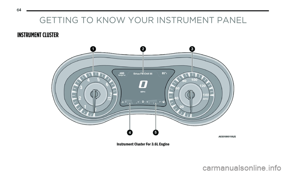
INSTRUMENT CLUSTER
Instrument Cluster For 3.6L Engine