Page 145 of 268
. The zone length starts at the outside
r e
arvie")
SAFETY 143
BSM Warning Light
The BSM detection zone covers approximately one
la
ne width on both sides of the vehicle 12 ft
( 3
.8 m). The zone length starts at the outside
r e
arview mirror and extends approximately 10 ft
( 3
m) beyond the rear fascia/bumper of the
v e
hicle. The BSM system monitors the detection
zones on both sides of the vehicle when the vehicle
speed reaches approximately 6 mph (10 km/h) or
h i
gher and will alert the driver of vehicles in these
areas.
NOTE:
The BSM system DOES NOT alert the driver
about rapidly approaching vehicles that are
outside the detection zones.
The BSM system detection zone DOES NOT
change if your vehicle is towing a trailer. There -
fore, visually verify the adjacent lane is clear for
b ot
h your vehicle and trailer before making a lane change. If the trailer or other object (i.e.,
bicycle, sports equipment) extends beyond the
side of your vehicle, this may result in the BSM
warning light randomly alerting on the trailer or
even remaining illuminated the entire time the
vehicle is in a forward gear
Ú page 122.
The Blind Spot Monitoring (BSM) system may
experience drop outs (blinking on and off) of the
side mirror warning indicator lamps when a
motorcycle or any small object remains at the
side of the vehicle for extended periods of time
(more than a couple of seconds).
The BSM system can become blocked if snow, ice,
mu
d, or other road contaminations accumulate on
the rear fascia/bumper where the radar sensors
are located. The system may also detect blockage
if the vehicle is operated in areas with extremely
low radar returns such as a desert or parallel to a
large elevation drop. If blockage is detected, a
“Blind Spot Temporarily Unavailable, Wipe Rear
Corners” message will display in the cluster, both
mirror lights will illuminate, and BSM and RCP
alerts will not occur. This is normal operation. The
system will automatically recover and resume
function when the condition clears. To minimize
system blockage, do not block the area of the rear
fascia/bumper where the radar sensors are
located with foreign objects (bumper stickers,
bicycle racks, etc.) and keep it clear of road
contaminations.
Sensor Location (Driver Side Shown)
The BSM system notifies the driver of objects in the
d e
tection zones by illuminating the BSM warning
light located in the outside mirrors in addition to
sounding an audible (chime) alert and reducing the
radio volume if the corresponding turn signal is
activated
Ú page 146.
The BSM system monitors the detection zone from
t h
ree different entry points (side, rear, front) while
driving to see if an alert is necessary. The BSM
system will issue an alert during these types of
zone entries.
6
Page 146 of 268
144 SAFETY
Entering From The Side
Vehicles that move into your adjacent lanes from
ei
ther side of the vehicle.
Side Monitoring
Entering From The Rear
Vehicles that come up from behind your vehicle on
ei
ther side and enter the rear detection zone with
a relative speed of less than 31 mph (50 km/h).
Rear Monitoring
Overtaking Traffic
If you pass another vehicle slowly with a relative
sp
eed of less than 15 mph (24 km/h) and the
v e
hicle remains in the blind spot for approximately
1.5 seconds, the warning light will be illuminated.
If the difference in speed between the two vehicles
is greater than 15 mph (24 km/h), the warning
li
ght will not illuminate.
Overtaking/Approaching
The BSM system is designed not to issue an alert
on
stationary objects such as guardrails, posts,
walls, foliage, berms, etc. However, occasionally
the system may alert on such objects. This is
normal operation and your vehicle does not require
service.
Overtaking/Passing
Page 147 of 268

SAFETY 145
The BSM system will not alert you of objects that
are traveling in the opposite direction of the vehicle
in adjacent lanes
Ú page 254.
Opposing Traffic
Rear Cross Path (RCP) Detection — If
Equipped
RCP is intended to aid the driver when backing out
of parking spaces where their vision of oncoming
vehicles may be blocked. Proceed slowly and
cautiously out of the parking space until the rear
end of the vehicle is exposed. The RCP system will
then have a clear view of the cross traffic and if an
oncoming vehicle is detected, alert the driver.
RCP Detection Zones
RCP monitors the rear detection zones on both
si
des of the vehicle, for objects that are moving
toward the side of the vehicle with a minimum
speed of approximately 3 mph (5 km/h), to objects
m ov
ing a maximum of approximately 20 mph
( 3
2 km/h), such as in parking lot situations. When RCP is on and the vehicle is in REVERSE, the
d
r
iver is alerted using both the visual and audible
alarms, including reducing the radio volume.
NOTE:
In a parking lot situation, oncoming vehicles can be
b l
ocked by vehicles parked on either side. If the
sensors are blocked by other structures or
vehicles, the system will not be able to alert the
driver.
WARNING!
The Blind Spot Monitoring system is only an aid
to help detect objects in the blind spot zones.
The BSM system is not designed to detect
pedestrians, bicyclists, or animals. Even if your
vehicle is equipped with the BSM system, always
check your vehicle’s mirrors, glance over your
shoulder, and use your turn signal before
changing lanes. Failure to do so can result in
serious injury or death.
WARNING!
Rear Cross Path Detection (RCP) is not a backup
aid system. It is intended to be used to help a
driver detect an oncoming vehicle in a parking
lot situation. Drivers must be careful when
backing up, even when using RCP. Always check
carefully behind your vehicle, look behind you,
and be sure to check for pedestrians, animals,
other vehicles, obstructions, and blind spots
before backing up. Failure to do so can result in
serious injury or death.
6
Page 148 of 268

146 SAFETY
Blind Spot Modes
Blind Spot has three selectable modes of
operation that are available in the Uconnect
system.
Blind Spot Alert Lights Only
When operating in Blind Spot Alert mode, the BSM
sy
stem will provide a visual alert in the appropriate
side view mirror based on a detected object.
However, when the system is operating in Rear
Cross Path (RCP) mode, the system will respond
with both visual and audible alerts when a
detected object is present. Whenever an audible
alert is requested, the radio is muted.
Blind Spot Alert Lights/Chime
When operating in Blind Spot Alert Lights/Chime
m od
e, the BSM system will provide a visual alert in
the appropriate side view mirror based on a
detected object. If the turn signal is then activated,
and it corresponds to an alert present on that side
of the vehicle, an audible chime will also be
sounded. Whenever a turn signal and detected
object are present on the same side at the same
time, both the visual and audible alerts will be
issued. In addition to the audible alert the radio (if
on) will also be muted.
NOTE:
Whenever an audible alert is requested by the
B S
M system, the radio is also muted. When the system is in RCP, the system shall
r
e
spond with both visual and audible alerts when a
detected object is present. Whenever an audible
alert is requested, the radio is also muted. Turn/
hazard signal status is ignored; the RCP state
always requests the chime.
Blind Spot Alert Off
When the BSM system is turned off there will be no
v i
sual or audible alerts from either the BSM or RCP
systems.
NOTE:
The BSM system will store the current operating
m od
e when the vehicle is shut off. Each time the
vehicle is started the previously stored mode will
be recalled and used.
FORWARD COLLISION WARNING (FCW)
W
ITH MITIGATION OPERATION —
I
F EQUIPPED
FCW with Mitigation provides the driver with
audible warnings, visual warnings (within the
instrument cluster display), and may apply a brake
jerk to warn the driver when it detects a potential
frontal collision. The warnings and limited braking
are intended to provide the driver with enough time
to react, avoid or mitigate the potential collision.
NOTE:
FCW monitors the information from the forward
l ook
ing sensors, as well as the Electronic Stability
Control (ESC) system, to calculate the probability of
a forward collision. When the system determines
that a forward collision is probable, the driver will
be provided with audible and visual warnings and
may provide a brake jerk warning. If the driver does
not take action based upon these progressive
warnings, then the system will provide a limited
level of active braking to help slow the vehicle and
mitigate the potential forward collision. If the driver
reacts to the warnings by braking and the system
determines that the driver intends to avoid the
collision by braking but has not applied sufficient
brake force, the system will compensate and
provide additional brake force as required. If a
Forward Collision Warning with Mitigation event
begins at a speed below 20 mph (32 km/h), the
s y
stem may provide the maximum or partial
braking to mitigate the potential forward collision.
If the Forward Collision Warning with Mitigation
event stops the vehicle completely, the system will
hold the vehicle at standstill for two seconds and
then release the brakes.
Page 149 of 268

SAFETY 147
FCW Message
When the system determines a collision with the
ve
hicle in front of you is no longer probable, the
warning message will be deactivated
Ú page 254.
NOTE:
The minimum speed for FCW activation is
1
mph (2 km/h).
The FCW alerts may be triggered on objects
other than vehicles such as guard rails or sign
posts based on the course prediction. This is
expected and is a part of normal FCW activation
and functionality.
It is unsafe to test the FCW system. To prevent
such misuse of the system, after four Active
Braking events within an ignition cycle, the
Active Braking portion of FCW will be deacti
-
vated until the next ignition cycle.
The FCW system is intended for on-road use
only. If the vehicle is taken off-road, the FCW
system should be deactivated to prevent unnec -
essary warnings due to the surroundings.
Turning FCW On Or Off
NOTE:
The default status of FCW is on; this allows the
s y
stem to warn you of a possible collision with the
vehicle in front of you.
The Forward Collision activation/deactivation is
l oc
ated in "Uconnect Settings" under "Safety And
Driving Assistance". Forward Collision can be
checked or unchecked.
When FCW is selected off, there will be an "FCW
OF
F" icon that appears in the instrument cluster
display. Changing the FCW status to off prevents the
s
y
stem from warning you of a possible collision
with the vehicle in front of you.
NOTE:
The FCW system’s default state is on. The FCW
s y
stem state is kept in memory from one ignition
cycle to the next. If the system is turned off, it will
remain off when the vehicle is restarted.
Changing FCW And Active Braking Status
The FCW Sensitivity and Active Braking settings are
programmable through the Uconnect system
Ú page 122.
The default status of FCW is the “Far” setting and
t h
e Active Braking is set to “on”; this allows the
system to warn you of a possible collision with the
vehicle in front of you when you are farther away
and it applies limited braking. This gives you the
most reaction time to avoid a possible collision.
Changing the FCW status to the “Near” setting,
a l
lows the system to warn you of a possible
collision with the vehicle in front of you when you
are much closer. This setting provides less
reaction time than the “Far” setting, which allows
for a more dynamic driving experience.
NOTE:
The system will retain the last setting selected
by the driver after ignition shut down.
FCW may not react to irrelevant objects such as
overhead objects, ground reflections, objects
WARNING!
Forward Collision Warning (FCW) is not intended
to avoid a collision on its own, nor can FCW
detect every type of potential collision. The driver
has the responsibility to avoid a collision by
controlling the vehicle via braking and steering.
Failure to follow this warning could lead to
serious injury or death.
6
Page 150 of 268

148 SAFETY
not in the path of the vehicle, stationary objects
that are far away, oncoming traffic, or leading
vehicles with the same or higher rate of speed.
FCW disables in the same manner as ACC, and
will display a screen indicating that the feature
is unavailable when it has been disabled.
FCW Limited Warning
If the instrument cluster display reads “ACC/FCW
Limited Functionality” or “ACC/FCW Limited
Functionality Clean Front Windshield”
momentarily, there may be a condition that limits
FCW functionality. Although the vehicle is still
drivable under normal conditions, the active
braking may not be fully available. Once the
condition that limited the system performance is
no longer present, the system will return to its full
performance state. If the problem persists, see an
authorized dealer.
Service FCW Warning
If the system turns off, and the instrument cluster
display reads:
ACC/FCW Unavailable Service Required
Cruise/FCW Unavailable Service Required
This indicates there is an internal system fault.
A l
though the vehicle is still drivable under normal
conditions, have the system checked by an
authorized dealer.
TIRE PRESSURE MONITORING SYSTEM
(TPMS)
The Tire Pressure Monitoring System (TPMS) will
warn the driver of a low tire pressure based on the
vehicle recommended cold placard pressure.
The tire pressure will vary with temperature by
a b
out 1 psi (7 kPa) for every 12°F (6.5°C). This
means that when the outside temperature
decreases, the tire pressure will decrease. Tire
pressure should always be set based on cold
inflation tire pressure. This is defined as the tire
pressure after the vehicle has not been driven for
at least three hours, or driven less than 1 mile
( 1
.6 km) after a three hour period. The cold tire
i n
flation pressure must not exceed the maximum
inflation pressure molded into the tire sidewall.
The tire pressure will also increase as the vehicle
is driven — this is normal and there should be no
adjustment for this increased pressure.
See
Ú page 225 on how to properly inflate the
vehicle’s tires.
The TPMS will warn the driver of a low tire pressure
i f
the tire pressure falls below the low-pressure
warning limit for any reason, including low
temperature effects and natural pressure loss
through the tire.
The TPMS will continue to warn the driver of low
t i
re pressure as long as the condition exists, and
will not turn off until the tire pressure is at or above the recommended cold placard pressure. Once the
low tire pressure warning (TPMS Warning Light)
illuminates, you must increase the tire pressure to
the recommended cold placard pressure in order
for the TPMS Warning Light to turn off. The system
will automatically update and the TPMS Warning
Light will turn off once the system receives the
updated tire pressures. The vehicle may need to be
driven for up to 20
minutes above 15 mph
( 2
4 km/h) in order for the TPMS to receive this
i n
formation.
NOTE:
When filling warm tires, the tire pressure may need
t o
be increased up to an additional 4 psi (28 kPa)
above the recommended cold placard pressure in
order to turn the TPMS Warning Light off.
For example, your vehicle may have a
re
commended cold (parked for more than three
hours) placard pressure of 30 psi (207 kPa). If the
ambient temperature is 68°F (20°C) and the
measured tire pressure is 27 psi (186 kPa), a
temperature drop to 20°F (-7°C) will decrease the
tire pressure to approximately 23 psi (158 kPa).
This tire pressure is sufficiently low enough to turn
on the TPMS Warning Light. Driving the vehicle
may cause the tire pressure to rise to
approximately 27 psi (186 kPa), but the TPMS
Warning Light will still be on. In this situation, the
TPMS Warning Light will turn off only after the tires
are inflated to the vehicle’s recommended cold
placard pressure value.
Page 151 of 268

SAFETY 149
NOTE:
The TPMS is not intended to replace normal tire
care and maintenance or to provide warning of
a tire failure or condition.
The TPMS should not be used as a tire pressure
gauge while adjusting your tire pressure.
Driving on a significantly underinflated tire
causes the tire to overheat and can lead to tire
failure. Underinflation also reduces fuel effi
-
ciency and tire tread life, and may affect the
v e
hicle’s handling and stopping ability.
The TPMS is not a substitute for proper tire
maintenance, and it is the driver’s responsibility
to maintain correct tire pressure using an accu -
rate tire pressure gauge, even if underinflation
h a
s not reached the level to trigger illumination
of the TPMS Warning Light.
Seasonal temperature changes will affect tire
pressure, and the TPMS will monitor the actual
tire pressure in the tire.
The Tire Pressure Monitoring System (TPMS) uses
w i
reless technology with wheel rim mounted
electronic sensors to monitor tire pressure levels.
Sensors, mounted to each wheel as part of the
valve stem, transmit tire pressure readings to the
receiver module
Ú page 254.
NOTE:
It is particularly important for you to check the tire
p r
essure in all of the tires on your vehicle monthly
and to maintain the proper pressure.
The TPMS consists of the following components:
Receiver module.
Four Tire Pressure Monitoring System sensors.
Various Tire Pressure Monitoring System
messages, which display in the instrument
cluster.
Tire Pressure Monitoring System Warning Light.
Tire Pressure Monitoring System Low
Pressure Warnings
The Tire Pressure Monitoring System
(TPMS) Warning Light will illuminate in
t h
e instrument cluster and a chime will
sound when tire pressure is low in one or
more of the four active road tires. In addition, the
instrument cluster will display an “Inflate to XX”
message and a graphic showing the pressure
values of each tire with the low tire pressure values
shown in a different color.
CAUTION!
The TPMS has been optimized for the original
equipment tires and wheels. TPMS pressures
and warning have been established for the tire
size equipped on your vehicle. Undesirable
system operation or sensor damage may
result when using replacement equipment
that is not of the same size, type, and/or style.
The TPMS sensor is not designed for use on
aftermarket wheels and may contribute to a
poor overall system performance or sensor
damage. Customers are encouraged to use
Original Equipment Manufacturer (OEM)
wheels to ensure proper TPMS feature opera -
tion.
Using aftermarket tire sealants may cause the
Tire Pressure Monitoring System (TPMS)
sensor to become inoperable. After using an
aftermarket tire sealant it is recommended
that you take your vehicle to an authorized
dealer to have your sensor function checked.
After inspecting or adjusting the tire pressure
always reinstall the valve stem cap. This will
prevent moisture and dirt from entering the
valve stem, which could damage the TPMS
sensor.
6
Page 152 of 268

150 SAFETY
Tire Pressure Monitoring System Display
Low Tire Pressure Monitoring System Display
Should this occur, you should stop as soon as
p os
sible and inflate the tires with a low pressure
condition (those shown in a different color in the
instrument cluster graphic) to the vehicle’s
recommended cold placard pressure inflation
value as shown in the “Inflate to XX” message.
Once the system receives the updated tire pressures, the system will automatically update,
the graphic display in the instrument cluster will
change color back to the original color, and the
TPMS Warning Light will turn off. The vehicle may
need to be driven for up to 20
minutes above
1 5
mph (24 km/h) in order for the TPMS to receive
t h
is information.
NOTE:
When filling warm tires, the tire pressure may need
t o
be increased up to an additional 4 psi (28 kPa)
above the recommended cold placard pressure in
order to turn the TPMS Warning Light off.
Service Tire Pressure System Warning
If a system fault is detected, the Tire Pressure
Monitoring System (TPMS) Warning Light will flash
on and off for 75 seconds and then remain on
solid. The system fault will also sound a chime. In
addition, the instrument cluster will display a
"Service Tire Pressure System" message for a
minimum of five seconds and then display dashes
(- -) in place of the pressure value to indicate which
sensor is not being received.
If the ignition switch is cycled, this sequence will
r e
peat, providing the system fault still exists. If the
system fault no longer exists, the TPMS Warning
Light will no longer flash, and the "Service Tire
Pressure System" message will no longer display,
and a pressure value will display in place of the
dashes. A system fault can occur due to any of the
following:
Signal interference due to electronic devices or
driving next to facilities emitting the same radio
frequencies as the TPMS sensors.
Accumulation of snow or ice around the wheels
or wheel housings.
Using tire chains on the vehicle.
Using wheels/tires not equipped with TPMS
sensors.
Vehicles With Compact Spare
1. T he compact spare tire or non-matching full
s
ize does not have a Tire Pressure Monitoring
System sensor. Therefore, the TPMS will not
monitor the pressure in the compact spare
tire.
2. I f you install the compact or non-matching full
s
ize spare tire in place of a road tire that has a
pressure below the low-pressure warning limit,
upon the next ignition key cycle, the TPMS
Warning Light will remain on and a chime will
sound. In addition, the graphic in the
instrument cluster will still display a different
color pressure value and an "Inflate to XX"
message.
 1
1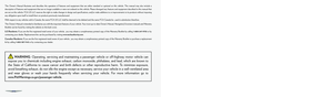 2
2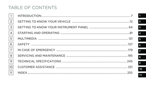 3
3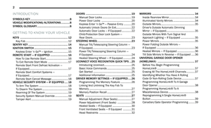 4
4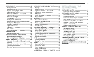 5
5 6
6 7
7 8
8 9
9 10
10 11
11 12
12 13
13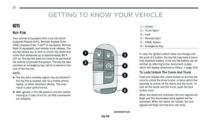 14
14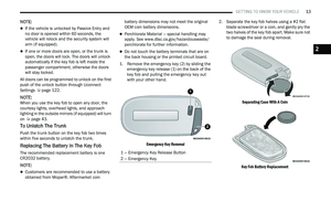 15
15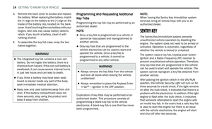 16
16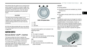 17
17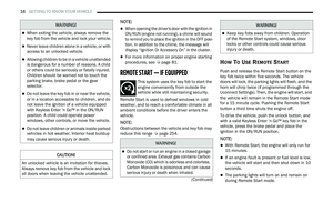 18
18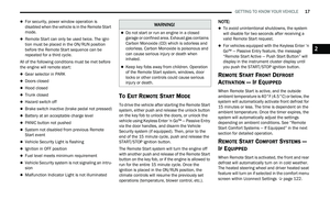 19
19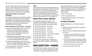 20
20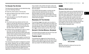 21
21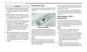 22
22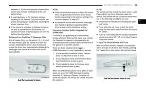 23
23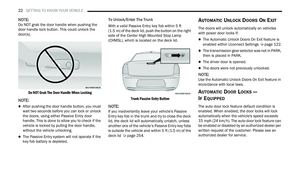 24
24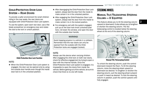 25
25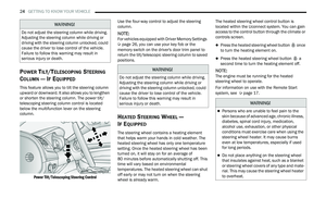 26
26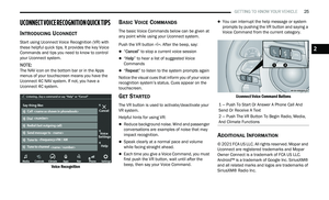 27
27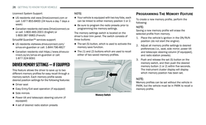 28
28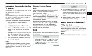 29
29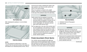 30
30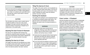 31
31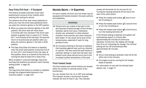 32
32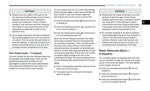 33
33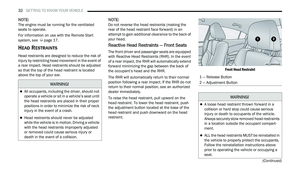 34
34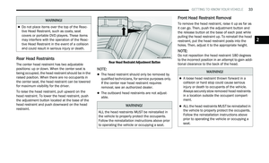 35
35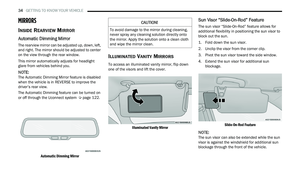 36
36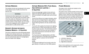 37
37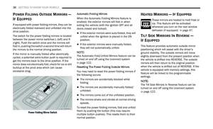 38
38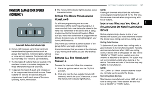 39
39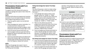 40
40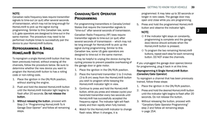 41
41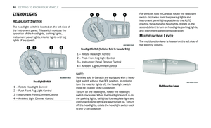 42
42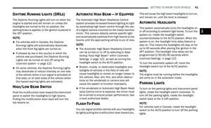 43
43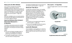 44
44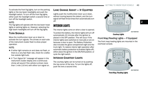 45
45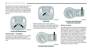 46
46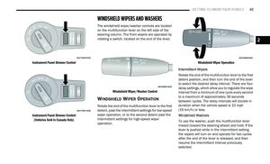 47
47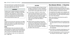 48
48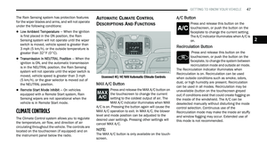 49
49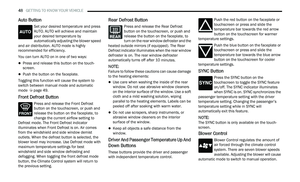 50
50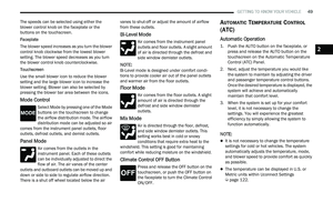 51
51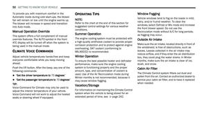 52
52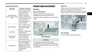 53
53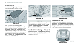 54
54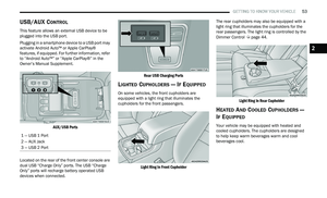 55
55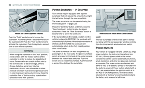 56
56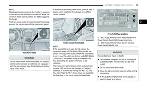 57
57 58
58 59
59 60
60 61
61 62
62 63
63 64
64 65
65 66
66 67
67 68
68 69
69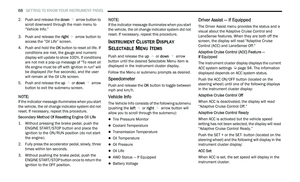 70
70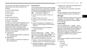 71
71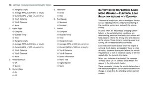 72
72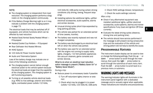 73
73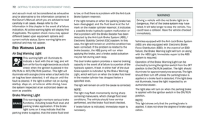 74
74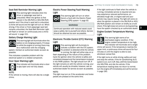 75
75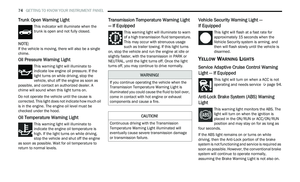 76
76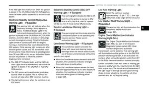 77
77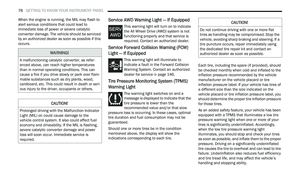 78
78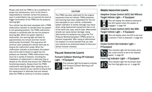 79
79 80
80 81
81 82
82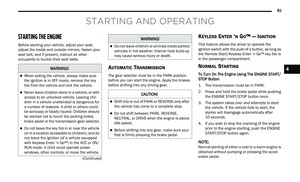 83
83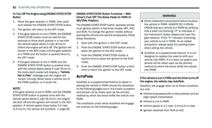 84
84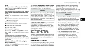 85
85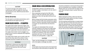 86
86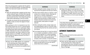 87
87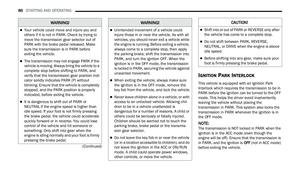 88
88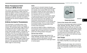 89
89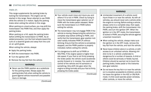 90
90 91
91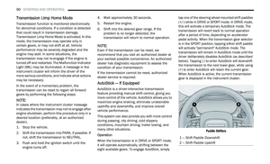 92
92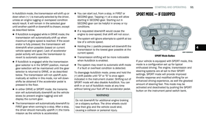 93
93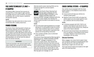 94
94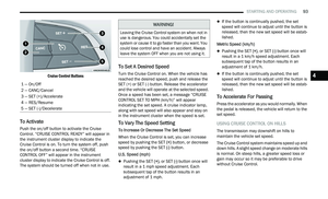 95
95 96
96 97
97 98
98 99
99 100
100 101
101 102
102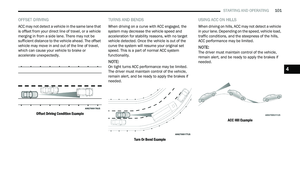 103
103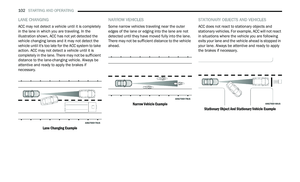 104
104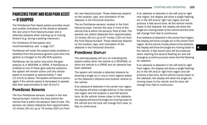 105
105 106
106 107
107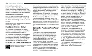 108
108 109
109 110
110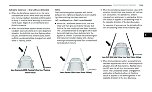 111
111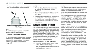 112
112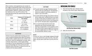 113
113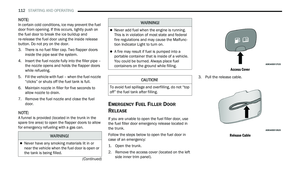 114
114 115
115 116
116 117
117 118
118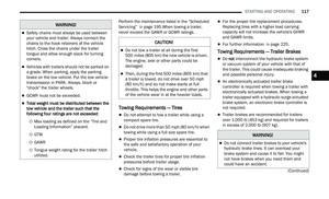 119
119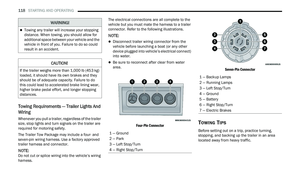 120
120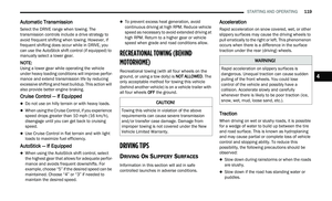 121
121 122
122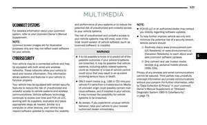 123
123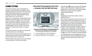 124
124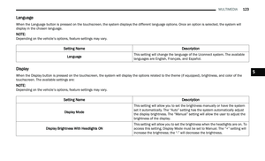 125
125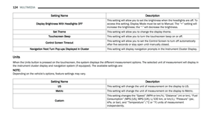 126
126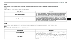 127
127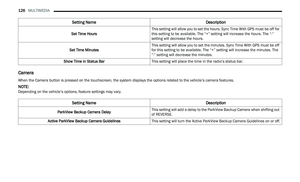 128
128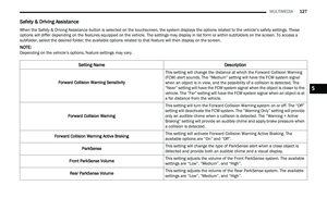 129
129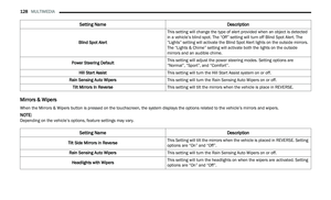 130
130 131
131 132
132 133
133 134
134 135
135 136
136 137
137 138
138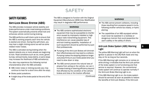 139
139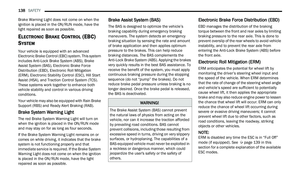 140
140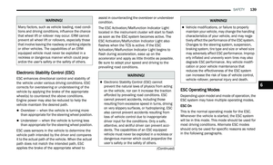 141
141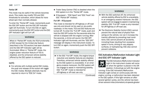 142
142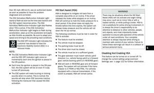 143
143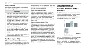 144
144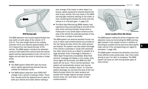 145
145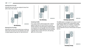 146
146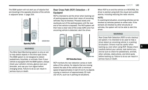 147
147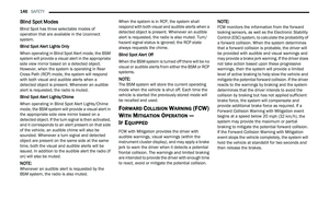 148
148 149
149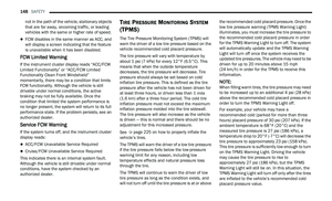 150
150 151
151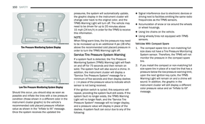 152
152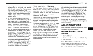 153
153 154
154 155
155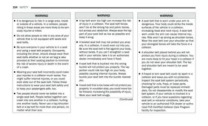 156
156 157
157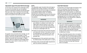 158
158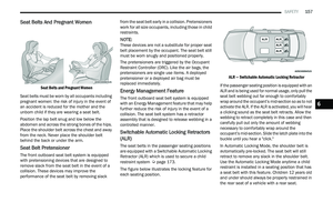 159
159 160
160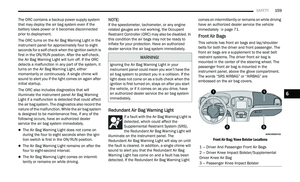 161
161 162
162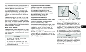 163
163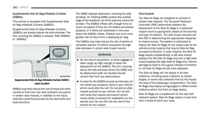 164
164 165
165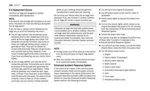 166
166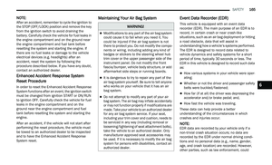 167
167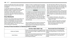 168
168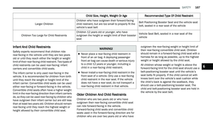 169
169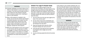 170
170 171
171 172
172 173
173 174
174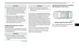 175
175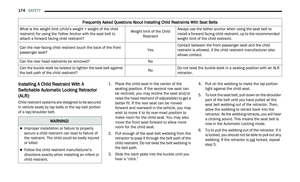 176
176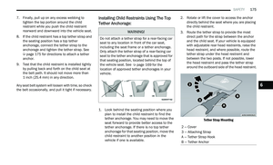 177
177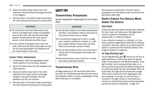 178
178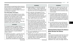 179
179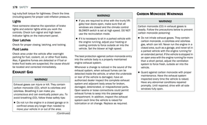 180
180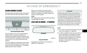 181
181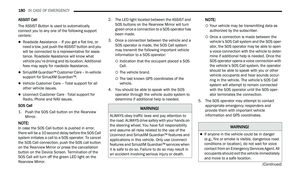 182
182 183
183 184
184 185
185 186
186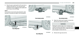 187
187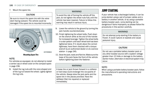 188
188 189
189 190
190 191
191 192
192 193
193 194
194 195
195 196
196 197
197 198
198 199
199 200
200 201
201 202
202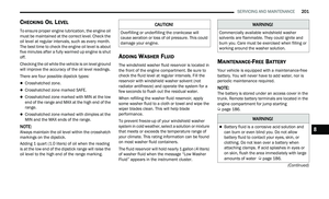 203
203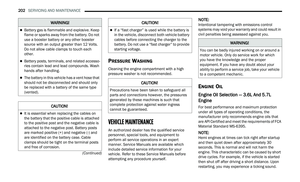 204
204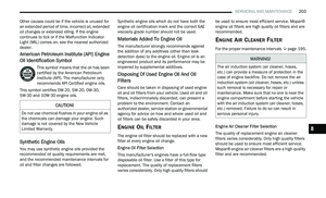 205
205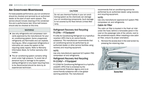 206
206 207
207 208
208 209
209 210
210 211
211 212
212 213
213 214
214 215
215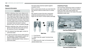 216
216 217
217 218
218 219
219 220
220 221
221 222
222 223
223 224
224 225
225 226
226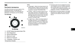 227
227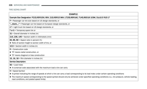 228
228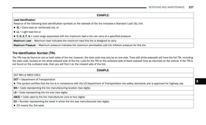 229
229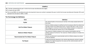 230
230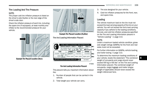 231
231 232
232 233
233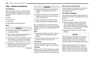 234
234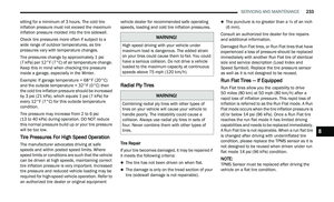 235
235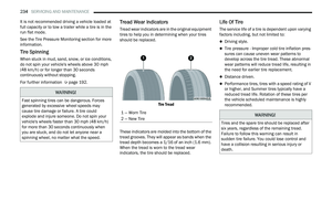 236
236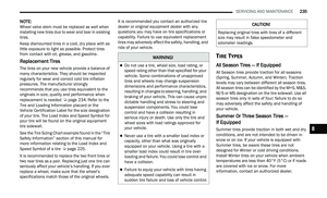 237
237 238
238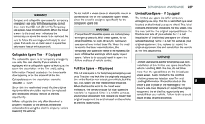 239
239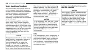 240
240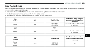 241
241 242
242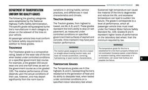 243
243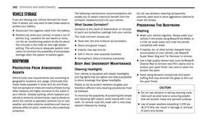 244
244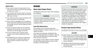 245
245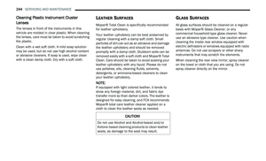 246
246 247
247 248
248 249
249 250
250 251
251 252
252 253
253 254
254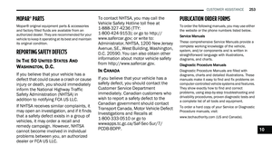 255
255 256
256 257
257 258
258 259
259 260
260 261
261 262
262 263
263 264
264 265
265 266
266 267
267