2021 ALFA ROMEO STELVIO oil
[x] Cancel search: oilPage 6 of 280
4
VEHICLE CHANGES / ALTERATIONS
Accessories Purchased By The Owner
If you decide to install electrical accessories that require a permanent electrical supply (e.g. radio, satellite anti-theft system, etc.) or accessories
that in any case drain the electrical supply after purchasing the vehicle, contact an authorized dealer. Dealer personnel will check whether the
vehicles's electrical system is able to withstand the load required or whether it needs to be integrated with a more powerful battery.
NOTE:
Use caution when adding additional spoilers, alloy wheel rims, or non-standard wheel hubs: they could reduce the ventilation of the brakes and
affect efficiency under sharp and repeated braking, or on long descents. Make sure that nothing obstructs the pedal (mats, etc.).
FCA US LLC shall not be liable for damage caused by the installation of accessories either not supplied or recommended by FCA US LLC and/or not
installed in compliance with the provided instructions.
Installing Electrical/Electronic Devices
FCA US LLC authorizes the installation of transceivers provided that installation is carried out at a specialized center, in compliance with manufac-
turer's specifications.
NOTE:
Local authorities may not allow the vehicle on the road if devices that modify the features of the vehicle have been installed. This also may void
the warranty in relation to faults caused by the change either directly or indirectly related to it.
FCA US LLC shall not be liable for damage caused by the installation of accessories either not supplied or recommended by FCA US LLC and/or not
installed in compliance with the provided instructions.
WARNING!
Any change or alteration of the vehicle might seriously affect its safety and road handling, thus causing accidents, in which the occupants could
even be fatally injured.
21_GU_OM_EN_USC_t.book Page 4
Page 14 of 280

12
JUMP STARTING .................................... 201
Remote Battery Connection Posts......202
Jump Starting Procedure.....................203
Bump Starting ..................................204
ENGINE OVERHEATING ......................... 204 MANUAL PARK RELEASE ...................... 205TOWING A DISABLED VEHICLE ............. 205
Four-Wheel Drive (AWD) Models .........206
TOW EYES .............................................. 206
ENHANCED ACCIDENT RESPONSE
SYSTEM (EARS) ..................................... 207EVENT DATA RECORDER (EDR) ............ 207
SERVICING AND MAINTENANCE
SCHEDULED SERVICING ....................... 208
Periodic Checks ...................................208
Heavy Usage Of The Vehicle ...............208
Maintenance Plan (2.0L Engine) ........209
Maintenance Plan (2.9L Engine) ........212
ENGINE COMPARTMENT....................... 214
Checking Levels — 2.0L Engine .......... 214
Checking Levels — 2.9L Engine .......... 215
Engine Oil ............................................. 215
Engine Coolant Fluid............................216
Washer Fluid For Windshield/
Headlights ............................................ 217 Brake Fluid ...........................................217
Automatic Transmission Activation
System Oil ............................................ 217 Useful Advice For Extending The Life Of
Your Battery..........................................217 Battery ..................................................217
Pressure Washing ................................ 218
BATTERY RECHARGING ......................... 218
Important Notes .................................. 218
VEHICLE MAINTENANCE ........................ 219
Engine Oil ............................................. 219
Engine Oil Filter ................................... 220
Engine Air Cleaner Filter ..................... 220
Air Conditioning System
Maintenance........................................ 220 Lubricating Moving Parts Of The
Bodywork ............................................. 220 Windshield Wiper................................. 221
Exhaust System ................................... 222
Cooling System .................................... 223
Braking System.................................... 224
Automatic Transmission ..................... 225
Replacing The Battery ......................... 225
Fuses .................................................... 225
Bulb Replacement ............................... 229
TIRES ...................................................... 233
Tire Safety Information .................... 233
Tires — General Information .............. 239
Spare Tires — If Equipped .................. 244
Wheel And Wheel Trim Care ............ 245
Tire Types ............................................. 246
Tire Chains and Traction Devices ....... 247
Tire Rotation Recommendations........ 247
DEPARTMENT OF TRANSPORTATION
UNIFORM TIRE QUALITY GRADES ......... 248
Treadwear ............................................ 248
Traction Grades ................................... 248
Temperature Grades ........................... 248
STORING THE VEHICLE ......................... 249 BODYWORK ........................................... 249
Protection Against Atmospheric
Agents .................................................. 249 Corrosion Warranty ............................. 250
Preserving The Bodywork .................. 250
INTERIORS ............................................. 251
Seats And Fabric Parts ....................... 251
Leather Seats ...................................... 251
Plastic And Coated Parts .................... 251
Alcantara Parts — If Equipped ............ 251
Genuine Leather Parts........................ 251
Carbon Fiber Parts .............................. 252
TECHNICAL SPECIFICATIONS
VEHICLE IDENTIFICATION
NUMBER (VIN) ....................................... 253
Vehicle Identification Number............ 253
Vehicle Identification Number
(VIN) Plate ............................................ 253
ENGINE .................................................. 254
POWER SUPPLY ..................................... 255 TRANSMISSION ..................................... 255BRAKES.................................................. 255
SUSPENSION ......................................... 256
STEERING .............................................. 256
DIMENSIONS ......................................... 257
Luggage Compartment Volume ......... 259
WEIGHTS ................................................ 259
21_GU_OM_EN_USC_t.book Page 12
Page 16 of 280
14
SYMBOL GLOSSARY
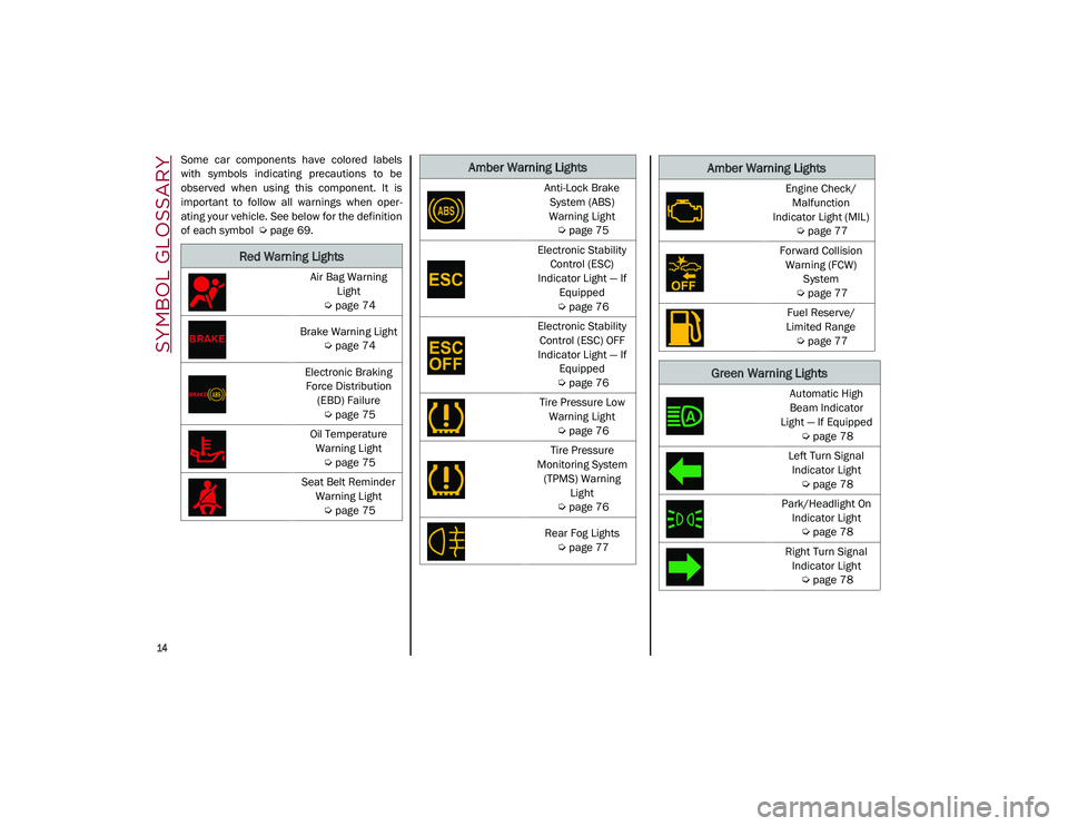
Some car components have colored labels
with symbols indicating precautions to be
observed when using this component. It is
important to follow all warnings when oper-
ating your vehicle. See below for the definition
of each symbol
Ú
page 69.
Red Warning Lights
Air Bag Warning
Light
Ú
page 74
Brake Warning Light
Ú
page 74
Electronic Braking Force Distribution (EBD) Failure
Ú
page 75
Oil Temperature Warning Light
Ú
page 75
Seat Belt Reminder Warning Light
Ú
page 75
Amber Warning Lights
Anti-Lock Brake
System (ABS)
Warning Light
Ú
page 75
Electronic Stability Control (ESC)
Indicator Light — If Equipped
Ú
page 76
Electronic Stability Control (ESC) OFF
Indicator Light — If Equipped
Ú
page 76
Tire Pressure Low Warning Light
Ú
page 76
Tire Pressure
Monitoring System (TPMS) Warning Light
Ú
page 76
Rear Fog Lights
Ú
page 77Engine Check/
Malfunction
Indicator Light (MIL)
Ú
page 77
Forward Collision Warning (FCW) System
Ú
page 77
Fuel Reserve/
Limited Range
Ú
page 77
Green Warning Lights
Automatic High
Beam Indicator
Light — If Equipped
Ú
page 78
Left Turn Signal Indicator Light
Ú
page 78
Park/Headlight On Indicator Light
Ú
page 78
Right Turn Signal Indicator Light
Ú
page 78
Amber Warning Lights
21_GU_OM_EN_USC_t.book Page 14
Page 17 of 280
15
Blue Warning Lights
High Beam Indicator Light — If Equipped
Ú
page 78
Red Symbols
Alfa Steering Torque
(AST) Failure
Ú
page 78
Alternator Failure
Ú
page 78
Automatic
Transmission Failure
Ú
page 78
Driver Attention
Assist (DAA) System Activation
Ú
page 78
Door Open
Ú
page 79
Power Steering Failure
Ú
page 79
Electronic Throttle Control (ETC)
Warning Light
Ú
page 79
Engine Coolant
Temperature Too High
Ú
page 79
Hood Cap Not Properly Shut
Ú
page 79
Insufficient Engine Oil Level
Ú
page 79
Low Engine Oil Pressure
Ú
page 79
Trunk Lid Not
Properly Shut
Ú
page 80
Amber Symbols
Engine Immobilizer
Failure/Break-In Attempt
Ú
page 80
Fuel Cut-Off
Indicator Light
Ú
page 80
Park Sensors
System Failure
Ú
page 80
Red Symbols
Engine Oil Change
Required— If Equipped
Ú
page 80
Engine Oil Pressure Sensor Failure
Ú
page 80
Engine Oil Level Sensor Failure
Ú
page 81
Forward Collision Warning (FCW)
System Failure — If Equipped
Ú
page 81
Stop/Start System Failure
Ú
page 81
Rain Sensor Failure
Ú
page 81
Dusk Sensor Failure
Ú
page 81
Blind Spot
Monitoring System Failure — If Equipped
Ú
page 81
Amber Symbols
21_GU_OM_EN_USC_t.book Page 15
Page 21 of 280
19
Perchlorate Material — special handling
may apply. See
www.dtsc.ca.gov/hazard -
ouswaste/perchlorate
for further informa -
tion.
Do not touch the battery terminals that are
on the back housing or the printed circuit
board.
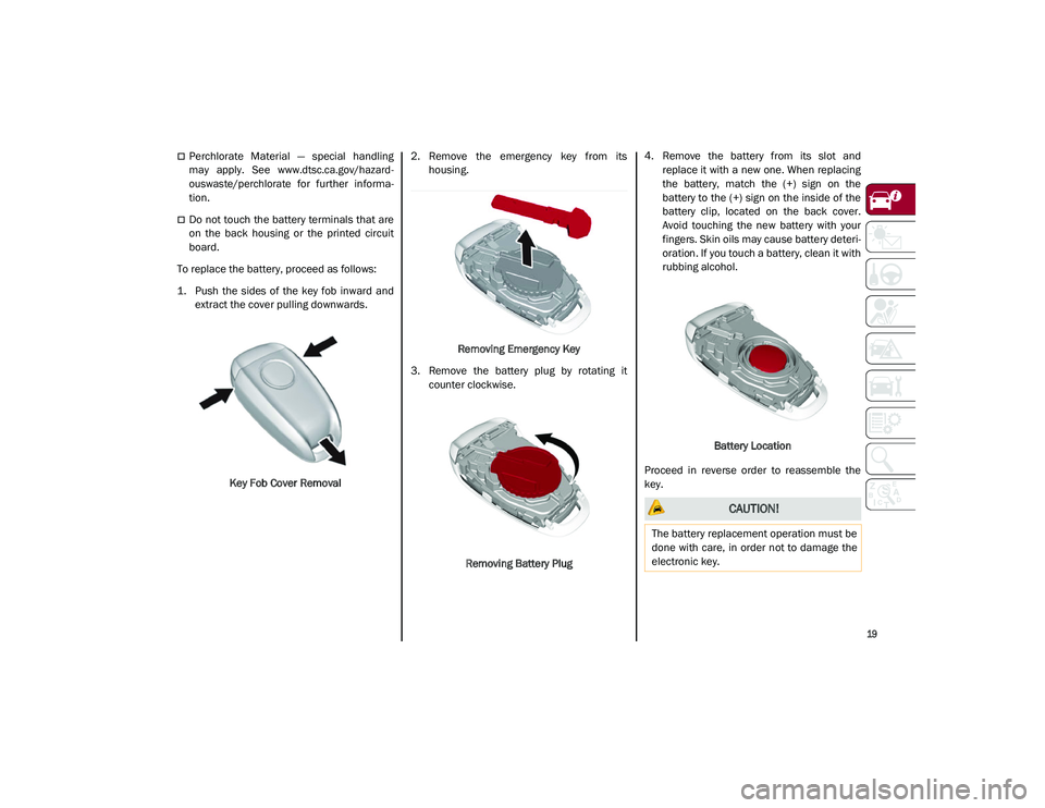
To replace the battery, proceed as follows:
1. Push the sides of the key fob inward and extract the cover pulling downwards.
Key Fob Cover Removal 2. Remove the emergency key from its
housing.
Removing Emergency Key
3. Remove the battery plug by rotating it counter clockwise.
Removing Battery Plug 4. Remove the battery from its slot and
replace it with a new one. When replacing
the battery, match the (+) sign on the
battery to the (+) sign on the inside of the
battery clip, located on the back cover.
Avoid touching the new battery with your
fingers. Skin oils may cause battery deteri -
oration. If you touch a battery, clean it with
rubbing alcohol.
Battery Location
Proceed in reverse order to reassemble the
key.
CAUTION!
The battery replacement operation must be
done with care, in order not to damage the
electronic key.
21_GU_OM_EN_USC_t.book Page 19
Page 70 of 280
GETTING TO KNOW YOUR INSTRUMENT PANEL
68
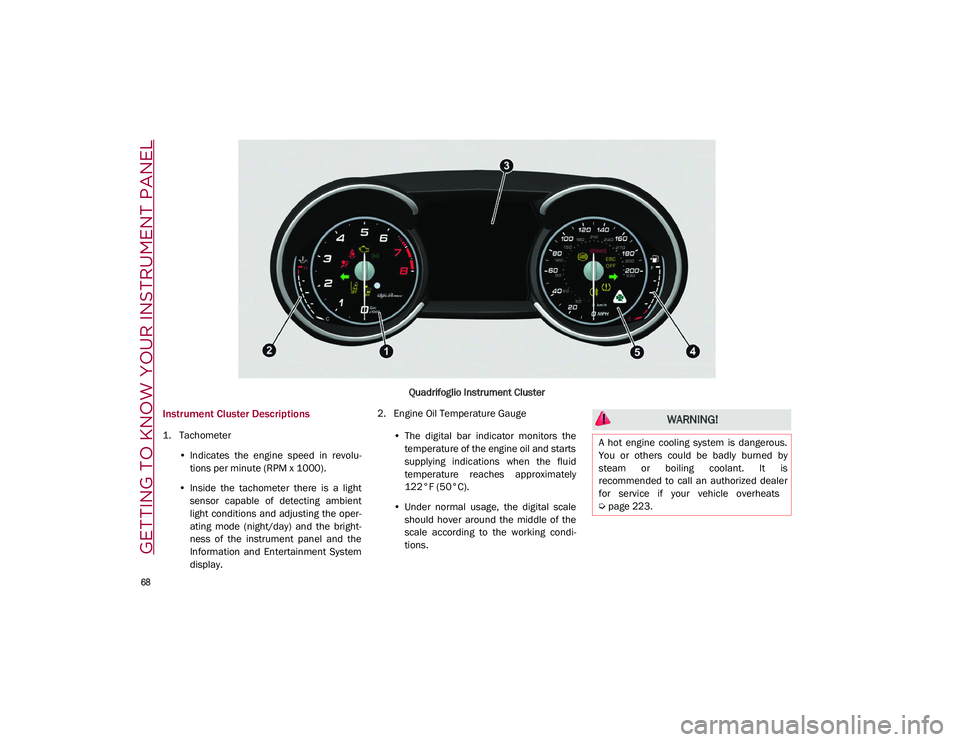
Quadrifoglio Instrument Cluster
Instrument Cluster Descriptions
1. Tachometer•Indicates the engine speed in revolu-
tions per minute (RPM x 1000).
• Inside the tachometer there is a light
sensor capable of detecting ambient
light conditions and adjusting the oper-
ating mode (night/day) and the bright-
ness of the instrument panel and the
Information and Entertainment System display. 2. Engine Oil Temperature Gauge
•The digital bar indicator monitors the
temperature of the engine oil and starts
supplying indic ations when the fluid
temperature reaches approximately
122°F (
50°C).
• Under normal usage, the digital scale
should hover around the middle of the
scale according to the working condi-
tions.
WARNING!
A hot engine cooling system is dangerous.
You or others could be badly burned by
steam or boiling coolant. It is
recommended to call an authorized dealer
for service if your vehicle overheats
Ú
page 223.
21_GU_OM_EN_USC_t.book Page 68
Page 74 of 280
GETTING TO KNOW YOUR INSTRUMENT PANEL
72
Normal and Advanced Efficiency
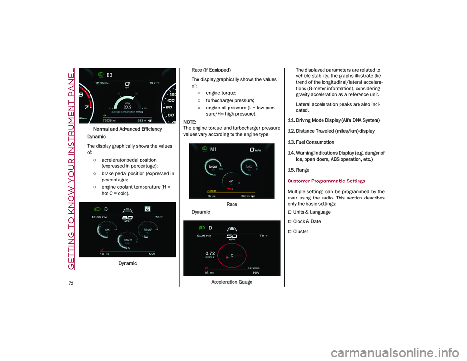
Dynamic
The display graphically shows the values
of: ○ accelerator pedal position (expressed in percentage);
○ brake pedal position (expressed in percentage);
○ engine coolant temperature (H = hot C = cold).
Dynamic Race (If Equipped)
The display graphically shows the values
of:
○ engine torque;
○ turbocharger pressure;
○ engine oil pressure (L = low pres -
sure/H= high pressure).
NOTE:
The engine torque and turbocharger pressure
values vary according to the engine type.
Race
Dynamic
Acceleration Gauge The displayed parameters are related to
vehicle stability, the graphs illustrate the
trend of the longitudinal/lateral accelera
-
tions (G-meter information), considering
gravity acceleration as a reference unit.
Lateral acceleration peaks are also indi -
cated.
11. Driving Mode Display (Alfa DNA System)
12. Distance Traveled (miles/km) display
13. Fuel Consumption
14. Warning Indications Display (e.g. danger of ice, open doors, ABS operation, etc.)
15. Range
Customer Programmable Settings
Multiple settings can be programmed by the
user using the radio. This section describes
only the basic settings:
Units & Language
Clock & Date
Cluster
21_GU_OM_EN_USC_t.book Page 72
Page 77 of 280
75
Vehicles equipped with the Anti-Lock Brake
System (ABS) are also equipped with Elec-
tronic Brake Force Distribution (EBD). In the
event of an EBD failure, the Brake Warning
Light will turn on along with the ABS Light.
Immediate repair to the ABS system is
required.
Operation of the Brake Warning Light can be
checked by turning the ignition switch from the
OFF position to the ON/RUN position. The light
should illuminate for approximately two
seconds. The light should then turn off unless
the parking brake is applied or a brake fault is
detected. If the light does not illuminate, have
the light inspected by an authorized dealer.
The light also will turn on when the parking
brake is applied with the ignition switch in the
ON/RUN position.
NOTE:
This light shows only that the parking brake is
applied. It does not show the degree of brake
application.
Seat Belt Reminder Warning Light
When the ignition is first placed in
the ON/RUN position, if the driver’s
seat belt is unbuckled, a chime will
sound and the light will turn on.
When driving, if the driver or front passenger
seat belt remains unbuckled, the Seat Belt
Reminder Light will flash or remain on contin -
uously and a chime will sound
Ú
page 163.
Electronic Brake Force Distribution (EBD)
Failure
The simultaneous turning on of the
BRAKE (red) and (amber) warning
lights with the engine on indicates
either a failure of the EBD system or
that the system is not available. In this case,
the rear wheels may suddenly lock and the
vehicle may swerve when braking abruptly.
Drive very carefully to the nearest authorized
dealer to have the system inspected immedi -
ately.
Oil Temperature Warning Light
This telltale indicates engine oil
temperature is high.
Stop the vehicle and shut off the engine as
soon as possible. If the problem persists,
contact an authorized dealer.
Amber Warning Lights
Anti-Lock Brake System (ABS) Warning Light
This light monitors the ABS. The light
will turn on when the ignition is
placed in the ON/RUN position and
may stay on for as long as four
seconds.
If the ABS light remains on or turns on while
driving, then the Anti-Lock portion of the brake
system is not functioning and service is
If the warning light does not turn on when
the ignition device is moved to ON or if it
stays on when driving (together with the
message on the display), there might be a
fault in the restraint systems; in this case,
the air bags or pretensioners may not
deploy in the event of an accident or, in a
lower number of cases, they could deploy
erroneously. Before proceeding, contact
an authorized dealer to have the system
checked immediately.
WARNING! (Continued)
WARNING!
The fault of the warning light is signaled by
the turning on of the icon on the instru -
ment panel. In this case, the warning light
may not indicate any faults with the
restraint systems. Before proceeding,
contact an authorized dealer to have the
system checked immediately.
If the warning light does not turn on when
the ignition device is moved to ON or if it
stays on when driving (together with the
message on the display), there might be a
fault in the restraint systems; in this case,
the air bags or pretensioners may not
deploy in the event of an accident or, in a
lower number of cases, they could deploy
erroneously. Before proceeding, contact
an authorized dealer to have the system
checked immediately.
21_GU_OM_EN_USC_t.book Page 75