2021 ALFA ROMEO STELVIO warning light
[x] Cancel search: warning lightPage 152 of 280
SAFETY
150
For the operation of the DAA, LDW, LKA, HAS,
TJA, ACC, ISC, or TSR systems, see
Ú
page 86.
NOTE:
When driving on two-way roads where there is
no lane dividing center line (e.g. on unpaved
roads), the use of the ABSA, HAS, TJA, and LKA
systems is strongly discouraged as the system
could detect the entire road as single-lane
dividing lines.
NOTE:
The driving assistance systems are designed
to aid in driving the car. The driver must always
maintain a sufficient level of attention to the
traffic and road conditions and control the
trajectory of the car.
Blind Spot Monitoring (BSM) System — If
Equipped
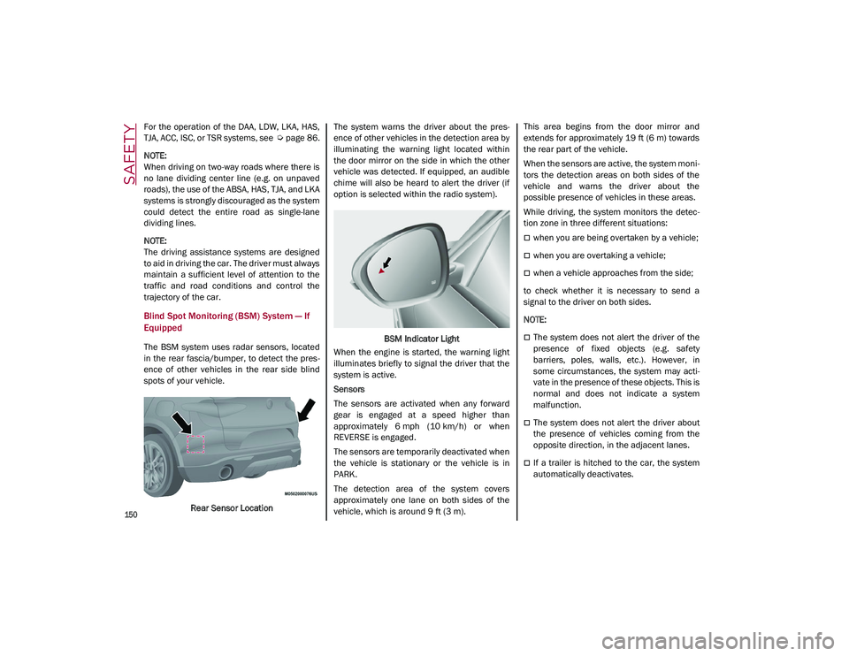
The BSM system uses radar sensors, located
in the rear fascia/bumper, to detect the pres -
ence of other vehicles in the rear side blind
spots of your vehicle.
Rear Sensor Location The system warns the driver about the pres
-
ence of other vehicles in the detection area by
illuminating the warning light located within
the door mirror on the side in which the other
vehicle was detected. If equipped, an audible
chime will also be heard to alert the driver (if
option is selected within the radio system).
BSM Indicator Light
When the engine is started, the warning light
illuminates briefly to signal the driver that the
system is active.
Sensors
The sensors are activated when any forward
gear is engaged at a speed higher than
approximately 6 mph (10 km/h) or when
REVERSE is engaged.
The sensors are temporarily deactivated when
the vehicle is stationary or the vehicle is in
PARK.
The detection area of the system covers
approximately one lane on both sides of the
vehicle, which is around 9 ft (3 m). This area begins from the door mirror and
extends for approximately 19 ft (6 m) towards
the rear part of the vehicle.
When the sensors are active, the system moni
-
tors the detection areas on both sides of the
vehicle and warns the driver about the
possible presence of vehicles in these areas.
While driving, the system monitors the detec -
tion zone in three different situations:
when you are being overtaken by a vehicle;
when you are overtaking a vehicle;
when a vehicle approaches from the side;
to check whether it is necessary to send a
signal to the driver on both sides.
NOTE:
The system does not alert the driver of the
presence of fixed objects (e.g. safety
barriers, poles, walls, etc.). However, in
some circumstances, the system may acti -
vate in the presence of these objects. This is
normal and does not indicate a system
malfunction.
The system does not alert the driver about
the presence of vehicles coming from the
opposite direction, in the adjacent lanes.
If a trailer is hitched to the car, the system
automatically deactivates.
21_GU_OM_EN_USC_t.book Page 150
Page 153 of 280
151
NOTE:
For the system to operate properly, the rear
fascia/bumper area where the radar
sensors are located must stay free from
snow, ice and dirt gathered from the road
surface.
Do not cover the rear fascia/bumper area
where the radar sensors are located with
any object (e.g. adhesives, bike rack, etc.).
If you wish to install a rear tow eye after
purchasing the vehicle, you will need to
deactivate the system via the radio system.
To access the function, select the following
items in sequence on the main menu:a. “Driver Assistance”
b. “Blind Spot Alert” Rear View
The system detects vehicles coming from the
rear part of your vehicle on both sides and
entering the rear detection area with a differ
-
ence in speed of less than 25 mph (40 km/h)
in relation to your vehicle.
Overtaking Vehicles
If another vehicle is overtaken slowly, with a
difference in speed of less than approximately
15 mph (25 km/h) and the vehicle stays in the
blind spot for approximately 1.5 seconds, the
warning light on the door mirror of the corre -
sponding side illuminates.
If the difference in speed between the two
vehicles is greater than approximately 15 mph
(25 km/h), the warning light does not illumi -
nate.
Rear Cross Path Detection (RCP) System
The Rear Cross Path Detection (RCP) system
assists the driver during reverse maneuvers in
the case of reduced visibility.
The RCP system monitors the rear detection
areas on both sides of the vehicle to detect
objects moving toward the sides of the vehicle,
with a minimum speed between approximately
1 mph (1 km/h) and 2 mph (3 km/h) and objects moving at a maximum speed of
21 mph (35 km/h), in areas such as parking
lots. The system activation is signaled to the driver
by an audible warning.
NOTE:
If the sensors are covered by objects or
vehicles, the system may not work as
intended.
For the system to operate correctly, the rear
fascia/bumper area where the radar
sensors are located must stay free from
snow, ice and dirt gathered from the road
surface.
Do not cover the rear fascia/bumper area
where the radar sensors are located with
any object (e.g. adhesives, bike rack, etc.).
WARNING!
The Blind Spot Monitoring system is only an
aid to help detect objects in the blind spot
zones. The BSM system is not designed to
detect pedestrians, bicyclists, or animals.
Even if your vehicle is equipped with the
BSM system, always check your vehicle’s
mirrors, glance over your shoulder, and use
your turn signal before changing lanes.
Failure to do so can result in serious injury
or death.
WARNING!
Rear Cross Path Detection (RCP) is not a
back up aid system. It is intended to be
used to help a driver detect an oncoming
vehicle in a parking lot situation. Drivers
must be careful when backing up, even
when using RCP. Always check carefully
behind your vehicle, look behind you, and
be sure to check for pedestrians, animals,
other vehicles, obstructions, and blind
spots before backing up. Failure to do so
can result in serious injury or death.
21_GU_OM_EN_USC_t.book Page 151
Page 154 of 280
SAFETY
152
Operating Mode
The system may be activated/deactivated via
the radio system. To access the function,
select the following items on the main menu in
sequence:
1. “Driving Assistance”
2. “Blind Spot Alert”
“Blind Spot Alert”, “Visual” Mode
When the system is enabled, the warning light
within the door mirror on the side of the
detected object illuminates.
The visual warning on the mirror will blink if the
driver activates the turn signals, indicating a
lane change.
The warning light will be constant if the driver
stays in the same lane.
“Blind Spot Alert” Function Deactivation
When the system is deactivated (“Blind Spot
Alert” mode off), the BSM or RCP systems will
not emit an audible or a visual warning.
The BSM system will store the operating mode
that was active when the engine was stopped.
Each time the engine is started, the operating
mode stored previously will be recalled and
used
Ú
page 268.
Active Blind Spot Assist (ABSA) System — If
Equipped
The ABSA system is to help avoid/limit lateral
collisions with cars coming from adjacent lanes changing the vehicle’s trajectory in order
to try to keep it in the detected lane.
The system warns the driver about the pres
-
ence of other vehicles in the detection area by
illuminating the warning light located within
the door mirror on the side in which the other
vehicle was detected and by means of an
acoustic signal and/or vibration on the
steering wheel and/or counter-steering torque
on the steering wheel (if the respective item on
the “Driver Assistance” menu is set up and
then “Safety” is selected on the radio system).
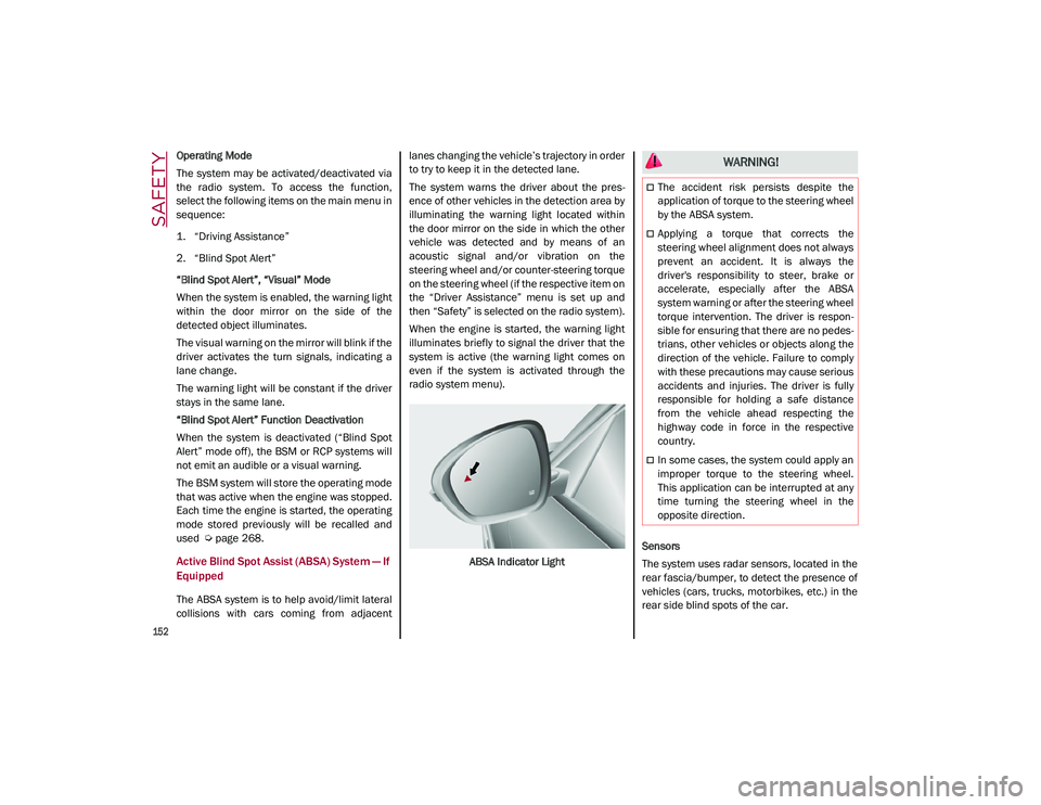
When the engine is started, the warning light
illuminates briefly to signal the driver that the
system is active (the warning light comes on
even if the system is activated through the
radio system menu).
ABSA Indicator Light Sensors
The system uses radar sensors, located in the
rear fascia/bumper, to detect the presence of
vehicles (cars, trucks, motorbikes, etc.) in the
rear side blind spots of the car.
WARNING!
The accident risk persists despite the
application of torque to the steering wheel
by the ABSA system.
Applying a torque that corrects the
steering wheel alignment does not always
prevent an accident. It is always the
driver's responsibility to steer, brake or
accelerate, especially after the ABSA
system warning or after the steering wheel
torque intervention. The driver is respon
-
sible for ensuring that there are no pedes -
trians, other vehicles or objects along the
direction of the vehicle. Failure to comply
with these precautions may cause serious
accidents and injuries. The driver is fully
responsible for holding a safe distance
from the vehicle ahead respecting the
highway code in force in the respective
country.
In some cases, the system could apply an
improper torque to the steering wheel.
This application can be interrupted at any
time turning the steering wheel in the
opposite direction.
21_GU_OM_EN_USC_t.book Page 152
Page 159 of 280
157
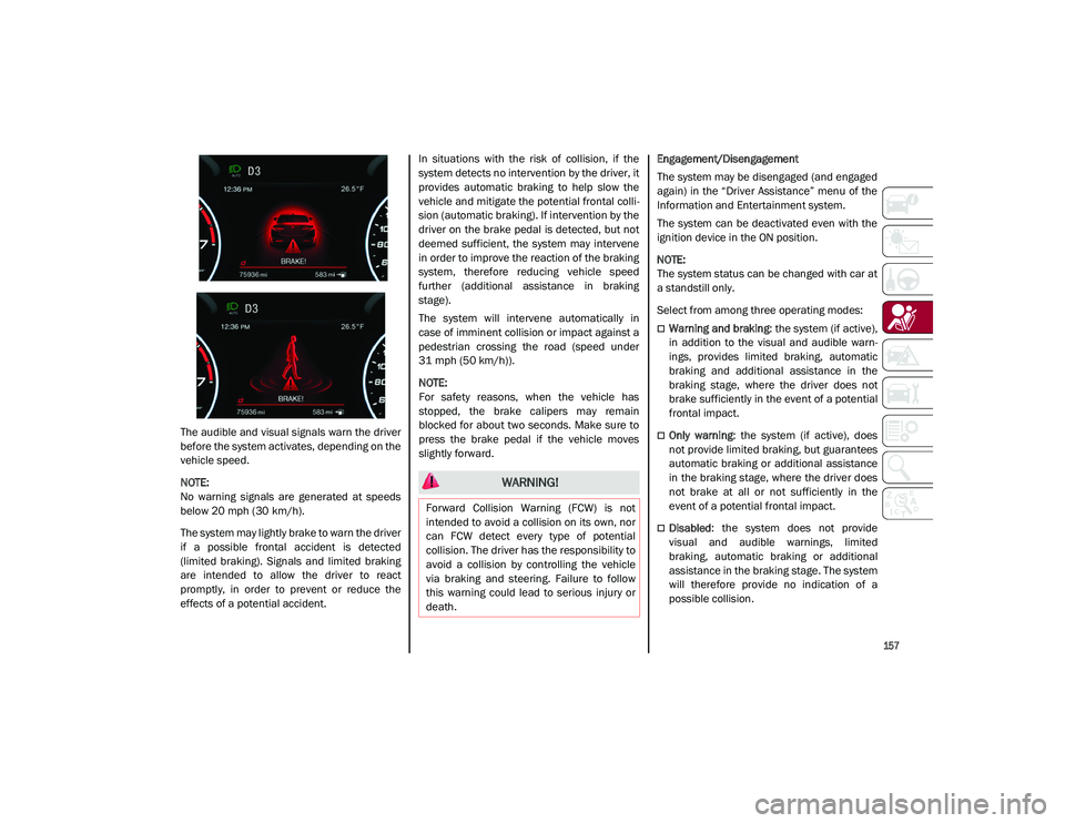
The audible and visual signals warn the driver
before the system activates, depending on the
vehicle speed.
NOTE:
No warning signals are generated at speeds
below 20 mph (30 km/h).The system may lightly brake to warn the driver
if a possible frontal accident is detected
(limited braking). Signals and limited braking
are intended to allow the driver to react
promptly, in order to prevent or reduce the
effects of a potential accident. In situations with the risk of collision, if the
system detects no intervention by the driver, it
provides automatic braking to help slow the
vehicle and mitigate the potential frontal colli
-
sion (automatic braking). If intervention by the
driver on the brake pedal is detected, but not
deemed sufficient, the system may intervene
in order to improve the reaction of the braking
system, therefore reducing vehicle speed
further (additional assistance in braking
stage).
The system will intervene automatically in
case of imminent collision or impact against a
pedestrian crossing the road (speed under
31 mph (50 km/h)).
NOTE:
For safety reasons, when the vehicle has
stopped, the brake calipers may remain
blocked for about two seconds. Make sure to
press the brake pedal if the vehicle moves
slightly forward. Engagement/Disengagement
The system may be disengaged (and engaged
again) in the “Driver Assistance” menu of the
Information and Entertainment system.
The system can be deactivated even with the
ignition device in the ON position.
NOTE:
The system status can be changed with car at
a standstill only.
Select from among three operating modes:
Warning and braking
: the system (if active),
in addition to the visual and audible warn -
ings, provides limited braking, automatic
braking and additional assistance in the
braking stage, where the driver does not
brake sufficiently in the event of a potential
frontal impact.
Only warning : the system (if active), does
not provide limited braking, but guarantees
automatic braking or additional assistance
in the braking stage, where the driver does
not brake at all or not sufficiently in the
event of a potential frontal impact.
Disabled : the system does not provide
visual and audible warnings, limited
braking, automatic braking or additional
assistance in the braking stage. The system
will therefore provide no indication of a
possible collision.
WARNING!
Forward Collision Warning (FCW) is not
intended to avoid a collision on its own, nor
can FCW detect every type of potential
collision. The driver has the responsibility to
avoid a collision by controlling the vehicle
via braking and steering. Failure to follow
this warning could lead to serious injury or
death.
21_GU_OM_EN_USC_t.book Page 157
Page 160 of 280
SAFETY
158
Activation/Deactivation
The Forward Collision Warning system is acti-
vated whenever the engine is started regard -
less of what is shown on the radio system.
Following a deactivation, the system will not
warn the driver about the possible collision
with a preceding vehicle, regardless of the
setting selected in the radio system.
NOTE:
Each time the engine is started, the system is
activated regardless of what setting was
selected when the engine was turned off.
This function is not active at a speed lower
than 4 mph (7 km/h) or higher than 124 mph
(200 km/h).
The system is active:
Each time the engine is started
When feature is selected within the radio
system
When the ignition is in the ON position
When the vehicle speed is between 2 mph
(4 km/h) and 124 mph (200 km/h)
When the front seat belts are fastened
The "Alfa DNA Pro" selector is not in RACE
position (if equipped)
NOTE:
If the seat belts of the front seats are not
correctly fastened, the system will not inter -vene on the braking system (only audible and
visual signals will be provided).
Changing The System Sensitivity
The sensitivity of the system can be changed
through the Information and Entertainment
system menu, choosing from one of the
following three options: "Near", "Medium" or
"Far". Refer to the description in the Informa
-
tion and Entertainment system Supplement
for how to change the settings.
The default setting is "Medium". With this
setting, the system warns the driver of a
possible collision with the vehicle in front
when that vehicle is at a standard distance,
between that of the other two settings.
With the system sensitivity set to "Far", the
system will warn the driver of a possible colli -
sion with the vehicle in front when that vehicle
is at a greater distance, thus providing the
possibility of acting on the brakes more lightly
and gradually. This setting provides the driver
with the maximum possible reaction time to
prevent a potential collision.
With the option set to "Near", the system will
alert the driver of a possible collision with the
vehicle in front when that vehicle is close. This
setting offers the driver a lower reaction time
compared to the "Medium" and "Far" settings,
in the event of a potential collision, but
permits more dynamic driving of the vehicle.
The system sensitivity setting is kept in the
memory when the engine is turned off. System Limited Operation Warning
If a dedicated message is displayed, a condi
-
tion limiting the system operation may have
occurred. The possible reasons of this limita -
tion are something is blocking the camera
view or a fault.
If an obstruction is signaled, clean the area of
the radar on the front fascia/bumper, and the
camera area on the windshield.
If a fault in the system is occurring, it will still
be possible to drive the vehicle normally, but
automatic braking will not be available in the
event of an impending collision.
When the conditions limiting the system func -
tions end, this will go back to normal and
complete operation. Should the fault persist,
contact an authorized dealer.
System Failure Signaling
If the system turns off and a dedicated
message is shown on the display, it means
that there is a fault with the system.
In this case, it is still possible to drive the
vehicle, but you are advised to contact an
authorized dealer as soon as possible.
Radar Indication Not Available
If conditions are such that the radar cannot
detect obstacles correctly, the system is deac -
tivated and a dedicated message appears on
the display. This generally occurs in the event
of poor visibility, such as when it is snowing or
raining heavily.
21_GU_OM_EN_USC_t.book Page 158
Page 163 of 280
161
Tire Pressure Monitoring System (TPMS)
The vehicle is equipped with a Tire Pressure
Monitoring System (TPMS) that sends the
inflation pressure information of each tire to
the control unit, and will signal the driver in the
event of insufficient tire pressure.
The TPMS uses wireless technology with wheel
rim mounted electronic sensors to monitor tire
pressure levels. Sensors, mounted to each
wheel as part of the valve stem, transmit tire
pressure readings to the receiver module.
Tire pressure will vary with temperature by
approximately 1 psi (7 kPa) for every 12°F
(6.5°C). This means that when the outside
temperature decreases, the tire pressure will
also decrease. Tire pressure should always be
set based on cold inflation tire pressure. This
is defined as the tire pressure after the vehicle
has not been driven for at least three hours, or
driven less than 1 mile (1.6 km) after a three
hour period. The cold tire inflation pressure
must not exceed the maximum inflation pres-
sure molded into the tire sidewall. The tire
pressure will also increase as the vehicle is
driven. This is normal, and there should be no
adjustment for this increased pressure.
See
Ú
page 233 for information on how to
properly inflate the vehicle’s tires.
The TPMS will signal the driver if pressure falls
below the warning limit for any reason,
including the effects of low temperature and
normal loss of pressure from the tire. The TPMS will stop indicating insufficient tire
pressure when pressure is equal to or greater
than the prescribed cold inflation level. There
-
fore, if insufficient tire pressure is indicated by
the ( ) warning light displaying in the instru -
ment cluster, increase the inflation pressure
up to the prescribed cold inflation value.
The system will automatically update, and the
TPMS Warning Light will turn off once the
system receives the updated tire pressures.
The vehicle may need to be driven for up to
20 minutes above 15 mph (24 km/h) in order
for the TPMS to receive this information.
NOTE:
The TPMS cannot indicate sudden tire pres -
sure drops (e.g. if a tire bursts). In this case,
proceed with caution and avoid abrupt
steering.
Operating Example
For example, your vehicle may have a recom -
mended cold (parked for more than three
hours) placard pressure of 33 psi (227 kPa). If
the ambient temperature is 68°F (20°C), and
the measured tire pressure is 28 psi (193 kPa),
a temperature drop to 20°F (-7°C) will
decrease the tire pressure to approximately
24 psi (165 kPa). This tire pressure is low
enough to turn on the “Tire Pressure Monitoring
Warning Light.” Driving the vehicle may cause
the tire pressure to rise to approximately 28 psi
(193 kPa), but the TPMS Warning Light will still
be on. In this situation, the TPMS Warning Light
WARNING!
The system has not been designed to
prevent impacts and cannot detect
possible conditions leading to an accident
in advance. Failure to take into account
this warning may lead to serious or fatal
injuries.
The system may activate, assessing the
trajectory of the vehicle, for the presence
of reflecting metal objects different from
other vehicles, such as safety barriers,
road signs, barriers before parking lots,
tollgates, level crossings, gates, railways,
objects near road constructions sites or
higher than the vehicle (e.g. a fly-over). In
the same way, the system may intervene
inside multi-story parking lots or tunnels,
or due to a glare on the road surface.
These possible activations are a conse -
quence of the real driving scenario
coverage by the system and must not be
regarded as faults.
The system has been designed for road
use only. If the vehicle is driven on a track,
the system must be deactivated to avoid
unnecessary warnings. Automatic deacti -
vation is signaled by the dedicated
warning light/symbol switching on in the
instrument panel
Ú
page 74.
21_GU_OM_EN_USC_t.book Page 161
Page 164 of 280
SAFETY
162
will turn off only after the tires are inflated to the
vehicle’s recommended cold placard pressure
value.Insufficient Tire Pressure Indication
If an insufficient pressure value is detected on
one or more tires, the warning light in the
instrument cluster will display alongside the
dedicated messages, the system will highlight
the tire or tires with insufficient pressure
graphically, and an acoustic signal will be
emitted.
In this case, stop the vehicle, check the infla
-
tion pressure of each tire, and inflate the
necessary tire or tires to the correct cold infla -
tion pressure value, shown on the display or in
the dedicated TPMS menu.
TPMS Temporarily Disabled:
TPMS Check Message
When a system fault is detected, the TPMS
Warning Light will flash on and off for 75 seconds,
and then remain on solid. The system fault will
also sound a chime. If the ignition is cycled, this
sequence will repeat, provided that the system
fault still exists. The TPMS Warning Light will turn
off when the fault condition no longer exists. A
system fault can occur due to any of the
following:
Jamming due to electronic devices or
driving next to facilities emitting the same
radio frequencies as the TPMS sensors.
Installing some form of aftermarket window
tinting that affects radio wave signals.
Packed snow or ice around the wheels or
wheel housings.
Using tire chains on the vehicle.
Using wheels/tires not equipped with TPMS
sensors.
After the punctured tire has been repaired
with the original tire sealant contained in the
Tire Kit, the previous condition must be
restored so that the warning light is off
during normal driving.
TPMS Deactivation
The TPMS can be deactivated by replacing all
four wheel and tire assemblies (road tires)
with wheel and tire assemblies that do not
have TPMS sensors, such as when installing
winter wheel and tire assemblies on your
vehicle.
To deactivate the TPMS, first replace all four
wheel and tire assemblies (road tires) with tires
not equipped with Tire Pressure Monitoring
System (TPMS) sensors. Then, drive the vehicle
for 20 minutes above 15 mph (24 km/h). The
TPMS will chime, the TPMS Warning Light will
flash on and off for 75 seconds and then
remain on. The instrument cluster will display
the “SERVICE TPM SYSTEM” message and then
display dashes (--) in place of the pressure
values.
Beginning with the next ignition switch cycle,
the TPMS will no longer chime or display the
“SERVICE TPM SYSTEM” message in the
instrument cluster. Instead, dashes (--) will
remain in place of the pressure values.
CAUTION!
The TPMS has been optimized for the orig -
inal equipment tires and wheels. TPMS
pressures and warning have been estab -
lished for the tire size equipped on your
vehicle. Undesirable system operation or
sensor damage may result when using
replacement equipment that is not of the
same size, type, and/or style. The TPMS
sensor is not designed for use on after -
market wheels and may contribute to a
poor overall system performance or
sensor damage. Customers are encour -
aged to use OEM wheels to assure proper
TPMS feature operation.
Using aftermarket tire sealants may cause
the Tire Pressure Monitoring System
(TPMS) sensor to become inoperable.
After using an aftermarket tire sealant it is
recommended that you take your vehicle
to an authorized dealer to have your
sensor function checked.
After inspecting or adjusting the tire pres -
sure always reinstall the valve stem cap.
This will prevent moisture and dirt from
entering the valve stem, which could
damage the TPMS sensor.
21_GU_OM_EN_USC_t.book Page 162
Page 165 of 280
163
To reactivate the TPMS, replace all four wheel
and tire assemblies (road tires) with tires
equipped with TPMS sensors. Then, drive the
vehicle for up to 20 minutes above 15 mph
(24 km/h). The TPMS will chime, the TPMS
Warning Light will flash on and off for 75
seconds and then turn off. The instrument
cluster will display the “SERVICE TPM
SYSTEM” message and then display pressure
values in place of the dashes. On the next igni-
tion switch cycle the “SERVICE TPM SYSTEM”
message will no longer be displayed, as long
as no system fault exists.
NOTE:
The TPMS is not intended to replace normal
tire care and maintenance, or to provide
warning of a tire failure or condition.
The TPMS should not be used as a tire pres -
sure gauge while adjusting your tire pres -
sure.
Driving on a significantly underinflated tire
will cause the tire to overheat, and can lead
to tire failure. Underinflation also reduces
fuel efficiency and tire tread life, and may
affect the vehicle’s handling and stopping
ability.
The TPMS is not a substitute for proper tire
maintenance, and it is the driver’s responsi -
bility to maintain correct tire pressure using
an accurate tire pressure gauge, even if underinflation has not reached the level to
trigger illumination of the TPMS Warning
Light.
Seasonal temperature changes will affect
tire pressure, and the TPMS will monitor the
actual tire pressure in the tire
Ú
page 268.
OCCUPANT RESTRAINT
SYSTEMS
Some of the most important safety features in
your vehicle are the restraint systems:
Occupant Restraint Systems Features
Seat Belt Systems
Supplemental Restraint Systems (SRS) Air
Bags
Child Restraints
Some of the safety features described in this
section may be standard equipment on some
models, or may be optional equipment on
others. If you are not sure, ask an authorized
dealer.
Important Safety Precautions
Please pay close attention to the information
in this section. It tells you how to use your
restraint system properly, to keep you and
your passengers as safe as possible. Here are some simple steps you can take to
minimize the risk of harm from a deploying air
bag:
1. Children 12 years old and under should
always ride buckled up in the rear seat of
a vehicle with a rear seat.
2. A child who is not big enough to wear the vehicle seat belt properly must be secured
in the appropriate child restraint or
belt-positioning booster seat in a rear
seating position
Ú
page 178.
3. If a child from 2 to 12 years old (not in a rear-facing child restraint) must ride in the
front passenger seat, move the seat as far
back as possible and use the proper child
restraint
Ú
page 178.
4. Never allow children to slide the shoulder belt behind them or under their arm.
5. You should read the instructions provided with your child restraint to make sure that
you are using it properly.
6. All occupants should always wear their lap and shoulder belts properly.
7. The driver and front passenger seats should be moved back as far as practical
to allow the front air bags room to inflate.
8. Do not lean against the door or window. If your vehicle has side air bags, and deploy -
ment occurs, the side air bags will inflate
21_GU_OM_EN_USC_t.book Page 163