2021 ALFA ROMEO STELVIO lock
[x] Cancel search: lockPage 57 of 280
55
Humidity Sensor
The Humidity Sensor helps prevent the
windows from fogging up. The AUTO function
(indicator illuminated) must be on for the
Humidity Sensor to function.
When outside temperature is low, the system
may turn the compressor on and turn air recir-
culation off for safer driving.
Stop/Start
The Stop/Start system shuts off the engine
when the vehicle speed is 0 mph (0 km/h), as
a fuel conservation measure.
In order to maintain comfort in the cabin, the
Stop/Start feature will not activate if any of the
following conditions exist:
The Climate Control system is in AUTO mode
(indicator illuminated), and the vehicle has
yet to reach the set temperature
The Climate Control system is in LO
maximum cooling
The Climate Control system is in HI
maximum heating
The Climate Control system is in the
MAX-DEF status
When the Stop/Start system is active, the
engine will restart if the inside temperature
changes significantly, or if the LO setting, or
MAX-DEF setting, is activated. With Stop/Start system on (engine is OFF), air
flow is reduced to keep the compartment
comfort conditions for longer.
Until the temperature drastically changes
within the cabin, the climate control system
will continue to maintain the temperature
while the engine is off. By deactivating the
Stop/Start system with the button (located
by the headlight switch), the climate control
system operates normally according to the
settings.
NOTE:
In harsh climate conditions, limit the use of
the Stop/Start system to prevent the
compressor from continuously switching on
and off. This will cause rapid misting of the
windows and the accumulation of humidity
in the passenger compartment.
When the Stop/Start system is on, the
climate control system will always take air in
from outside, reducing the probability of the
windows fogging up.
System Maintenance
In winter months, the Climate Control system
must be turned on at least once a month for
approximately 10 minutes.
Have the system inspected at an authorized
dealer before the summer.
INTERIOR STORAGE AND
EQUIPMENT
Glove Compartment
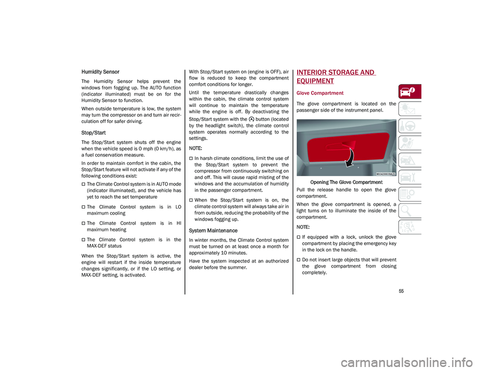
The glove compartment is located on the
passenger side of the instrument panel.
Opening The Glove Compartment
Pull the release handle to open the glove
compartment.
When the glove compartment is opened, a
light turns on to illuminate the inside of the
compartment.
NOTE:
If equipped with a lock, unlock the glove
compartment by placing the emergency key
in the lock on the handle.
Do not insert large objects that will prevent
the glove compartment from closing
completely.
21_GU_OM_EN_USC_t.book Page 55
Page 60 of 280
GETTING TO KNOW YOUR VEHICLE
58
Your mobile phone must be designed for Qi
wireless charging.
NOTE:
Do not place the key fob or any other type of
metal/magnetized object inside the mobile
phone housing or near the wireless
charging pad.
Be sure to place the mobile device correctly
(display facing upward) on the wireless
charging pad.
The ignition must be in the ON/RUN position
in order for the phone to charge.
To avoid interference with the key fob
search, the wireless charging pad will stop
charging when any door is opened.The following messages will display in the
radio system:
“Your phone is being charged” — The phone
has begun to charge.
“Phone Fully Charged” — The phone has
completed charging its battery.
“Foreign Object Detected” — The phone is
not enabled for wireless charging or an
object that is not permitted has been placed
on the wireless charging pad.
“Unavailable System” — There is a malfunc
-
tion with the wireless charging pad.
The driver can deactivate these messages
through the radio system. Refer to the Infor -
mation and Entertainment System Owner’s
Manual Supplement for further information.
POWER WINDOWS
Power Window Controls
The power window switches work with the igni -
tion in the ACC or ON/RUN position and for
three minutes after the ignition has been
placed in the OFF position. When one of the
front doors is opened, this operation is
disabled.
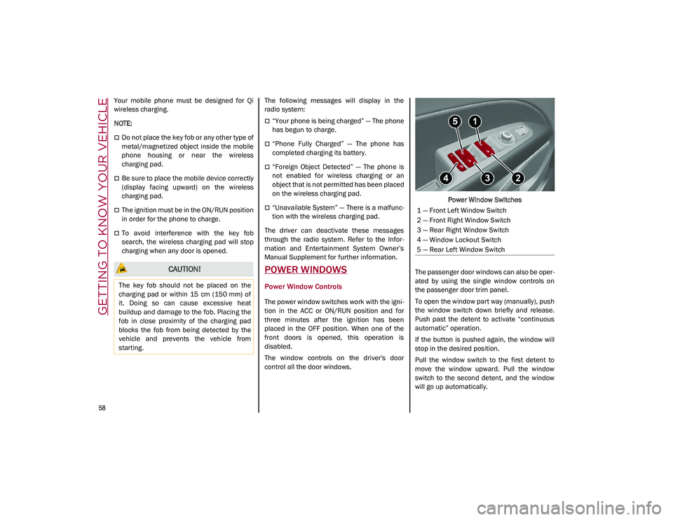
The window controls on the driver's door
control all the door windows. Power Window Switches
The passenger door windows can also be oper -
ated by using the single window controls on
the passenger door trim panel.
To open the window part way (manually), push
the window switch down briefly and release.
Push past the detent to activate “continuous
automatic” operation.
If the button is pushed again, the window will
stop in the desired position.
Pull the window switch to the first detent to
move the window upward. Pull the window
switch to the second detent, and the window
will go up automatically.
CAUTION!
The key fob should not be placed on the
charging pad or within 15 cm (150 mm) of
it. Doing so can cause excessive heat
buildup and damage to the fob. Placing the
fob in close proximity of the charging pad
blocks the fob from being detected by the
vehicle and prevents the vehicle from
starting.
1 — Front Left Window Switch
2 — Front Right Window Switch
3 — Rear Right Window Switch
4 — Window Lockout Switch
5 — Rear Left Window Switch
21_GU_OM_EN_USC_t.book Page 58
Page 62 of 280
GETTING TO KNOW YOUR VEHICLE
60
The sunroof has three preset positions:
Fully closed
Comfort (intermediate opening)
Fully open
NOTE:
You cannot have the sunshade closed when
the sunroof is open.
Opening And Closing The Sunroof
To open the sunroof’s front panel, push the
open/close button toward the rear of the
vehicle to open to the comfort position (half
way). Pushing the button a second time will
open to the fully open position.
To close the sunroof, push the open/close
button toward the front of the vehicle. The roof
will close completely.
The automatic motion can be interrupted in
any position by pushing the open/close button
again.
Venting Sunroof
To bring the roof into vent position, push and
release the vent button.
This type of vent opening can be activated
regardless of the position of the sunroof.
When starting with the roof in the closed posi -
tion, pushing the vent button automatically
causes the sunroof to open to the vent posi -
tion. If the roof is already open, the button
must be held until the roof reaches the
vent-opening position.
Pushing the vent button again during auto -
matic movement of the roof will stop it.
Sunshade Operation
The sunshade is power operated.
Push the Power Shade open/close button
toward the rear of the vehicle to open the sun
shade.
Push the Power Shade open/close button
toward the front of the vehicle to close the sun
shade.
The automatic motion can be interrupted in
any position by pushing the Power Shade
open/close button again.
Pinch Protect Feature
The sunroof has an anti-pinch safety system
capable of detecting the presence of an
obstacle during the closing movement. If an
obstacle is detected, the system intervenes
and the movement of the sunroof is immedi -
ately reversed.
Re-Initialization Procedure
Automatic operation of the sunroof must be
re-initialized in case of faulty sunroof opera -
tion. It may also be necessary to initialize the
sunroof after the vehicle’s battery has been
disconnected and then reconnected.
NOTE:
The anti-pinch safety device is deactivated
during the re-initialization procedure.
WARNING!
Never leave children unattended in a
vehicle, or with access to an unlocked
vehicle. Never leave the key fob in or near
the vehicle, or in a location accessible to chil -
dren. Do not leave the ignition of a vehicle
equipped with keyless ignition in the ON/
RUN mode. Occupants, particularly unat -
tended children, can become entrapped by
the power sunroof while operating the power
sunroof switch. Such entrapment may result
in serious injury or death.
In a collision, there is a greater risk of
being thrown from a vehicle with an open
sunroof. You could also be seriously
injured or killed. Always fasten your seat
belt properly and make sure all passen -
gers are also properly secured.
Do not allow small children to operate the
sunroof. Never allow your fingers, other
body parts, or any object, to project
through the sunroof opening. Injury may
result.
CAUTION!
Do not open the sun roof if a roof rack or
crossbars are fitted. Do not open the sun
roof if there is snow or ice on it: you may
damage it.
21_GU_OM_EN_USC_t.book Page 60
Page 64 of 280
GETTING TO KNOW YOUR VEHICLE
62
Closing The Hood
To close, lower the hood to approximately
16 inches (40 cm) from the engine compart-
ment then let it drop. Make sure that the hood
is completely closed and fully latched.
NOTE:
Since the hood is equipped with a double
locking system, one for each side, you must
check that it is closed on each side.
POWER LIFTGATE
Unlocking of the liftgate is electrically oper -
ated and is deactivated when the vehicle is in
motion.
If anything obstructs the power liftgate while it
is closing or opening, the liftgate will automat -
ically reverse to the closed or open position,
provided it meets sufficient resistance.
Opening
The liftgate may be released in several ways:
Pressing the liftgate release button on the
key fob twice within five seconds
Pushing the external liftgate release switch
(when the liftgate is unlocked)
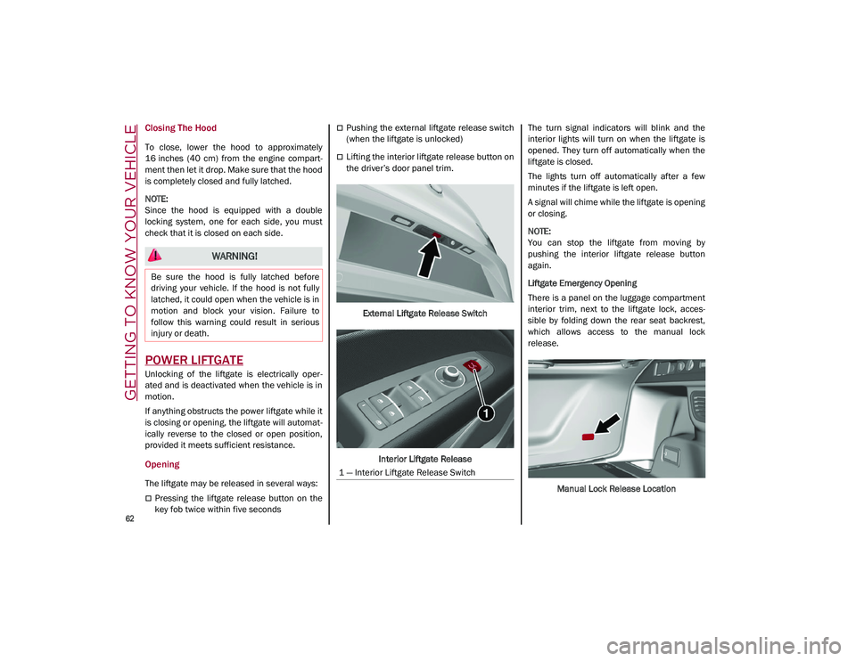
Lifting the interior liftgate release button on
the driver’s door panel trim.
External Liftgate Release Switch
Interior Liftgate Release The turn signal indicators will blink and the
interior lights will turn on when the liftgate is
opened. They turn off automatically when the
liftgate is closed.
The lights turn off automatically after a few
minutes if the liftgate is left open.
A signal will chime while the liftgate is opening
or closing.
NOTE:
You can stop the liftgate from moving by
pushing the interior liftgate release button
again.
Liftgate Emergency Opening
There is a panel on the luggage compartment
interior trim, next to the liftgate lock, acces
-
sible by folding down the rear seat backrest,
which allows access to the manual lock
release.
Manual Lock Release Location
WARNING!
Be sure the hood is fully latched before
driving your vehicle. If the hood is not fully
latched, it could open when the vehicle is in
motion and block your vision. Failure to
follow this warning could result in serious
injury or death.
1 — Interior Liftgate Release Switch
21_GU_OM_EN_USC_t.book Page 62
Page 65 of 280
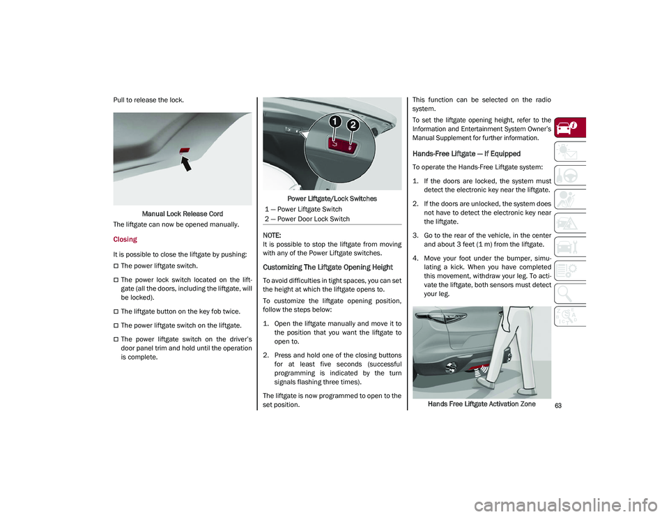
63
Pull to release the lock.Manual Lock Release Cord
The liftgate can now be opened manually.
Closing
It is possible to close the liftgate by pushing:
The power liftgate switch.
The power lock switch located on the lift -
gate (all the doors, including the liftgate, will
be locked).
The liftgate button on the key fob twice.
The power liftgate switch on the liftgate.
The power liftgate switch on the driver’s
door panel trim and hold until the operation
is complete. Power Liftgate/Lock Switches
NOTE:
It is possible to stop the liftgate from moving
with any of the Power Liftgate switches.
Customizing The Liftgate Opening Height
To avoid difficulties in tight spaces, you can set
the height at which the liftgate opens to.
To customize the liftgate opening position,
follow the steps below:
1. Open the liftgate manually and move it to the position that you want the liftgate to
open to.
2. Press and hold one of the closing buttons for at least five seconds (successful
programming is indicated by the turn
signals flashing three times).
The liftgate is now programmed to open to the
set position. This function can be selected on the radio
system.
To set the liftgate opening height, refer to the
Information and Entertainment System Owner’s
Manual Supplement for further information.
Hands-Free Liftgate — If Equipped
To operate the Hands-Free Liftgate system:
1. If the doors are locked, the system must
detect the electronic key near the liftgate.
2. If the doors are unlocked, the system does not have to detect the electronic key near
the liftgate.
3. Go to the rear of the vehicle, in the center and about 3 feet (1 m) from the liftgate.
4. Move your foot under the bumper, simu -
lating a kick. When you have completed
this movement, withdraw your leg. To acti -
vate the liftgate, both sensors must detect
your leg.
Hands Free Liftgate Activation Zone
1 — Power Liftgate Switch
2 — Power Door Lock Switch
21_GU_OM_EN_USC_t.book Page 63
Page 66 of 280
GETTING TO KNOW YOUR VEHICLE
64
(Continued)
If it is closed, the Hands-Free Liftgate unlocks
and opens completely, and with another
movement of the foot, it stops. A further move-
ment of the foot reverses the direction and
closes the liftgate completely, if you do not
stop it again.
If it is open, with a movement of the foot, the
Hands-Free Liftgate closes completely, and
with another movement of the foot, it stops. If
the liftgate is stopped, another movement of
the foot will reverse the direction and open it
completely.
NOTE:
To conserve the battery charge, avoid
performing this operation repeatedly with the
engine off.
You can activate/deactivate the Hands-Free
Liftgate on the radio system by pushing the
MENU button to select the Main menu, and
selecting the following items:
1. “Settings.”
2. “Doors And Locks.”
3. “Automatic Liftgate Opening.”
Liftgate Initialization
NOTE:
Automatic operation of the liftgate must be
initialized again in case of faulty liftgate opera -
tion. Proceed as follows:
1. Close all the doors and the liftgate.
2. Push the lock button on the key fob.
3. Push the unlock button on the key fob.
Cargo Area Features
Retractable Cargo Area Cover
The Retractable Cargo Area Cover can be
rolled up and removed.
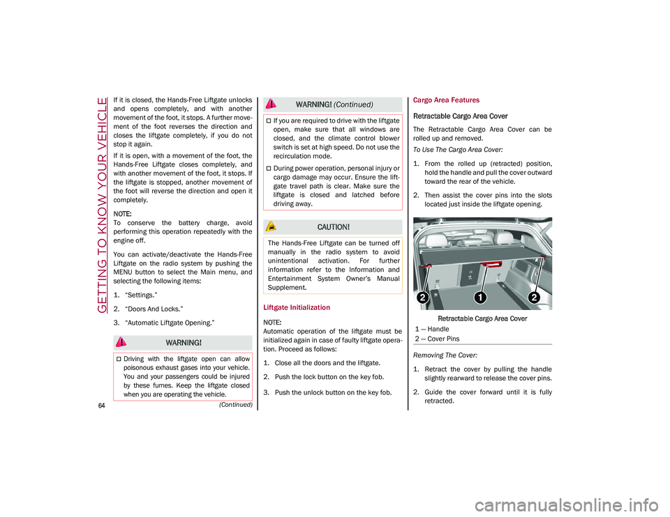
To Use The Cargo Area Cover:
1. From the rolled up (retracted) position, hold the handle and pull the cover outward
toward the rear of the vehicle.
2. Then assist the cover pins into the slots located just inside the liftgate opening.
Retractable Cargo Area Cover
Removing The Cover:
1. Retract the cover by pulling the handle slightly rearward to release the cover pins.
2. Guide the cover forward until it is fully retracted.
WARNING!
Driving with the liftgate open can allow
poisonous exhaust gases into your vehicle.
You and your passengers could be injured
by these fumes. Keep the liftgate closed
when you are operating the vehicle.
If you are required to drive with the liftgate
open, make sure that all windows are
closed, and the climate control blower
switch is set at high speed. Do not use the
recirculation mode.
During power operation, personal injury or
cargo damage may occur. Ensure the lift -
gate travel path is clear. Make sure the
liftgate is closed and latched before
driving away.
CAUTION!
The Hands-Free Liftgate can be turned off
manually in the radio system to avoid
unintentional activation. For further
information refer to the Information and
Entertainment System Owner’s Manual
Supplement.
WARNING! (Continued)
1 — Handle
2 — Cover Pins
21_GU_OM_EN_USC_t.book Page 64
Page 74 of 280
GETTING TO KNOW YOUR INSTRUMENT PANEL
72
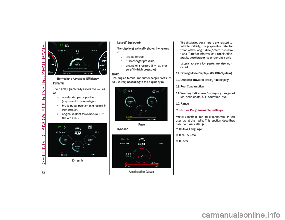
Normal and Advanced Efficiency
Dynamic
The display graphically shows the values
of: ○ accelerator pedal position (expressed in percentage);
○ brake pedal position (expressed in percentage);
○ engine coolant temperature (H = hot C = cold).
Dynamic Race (If Equipped)
The display graphically shows the values
of:
○ engine torque;
○ turbocharger pressure;
○ engine oil pressure (L = low pres -
sure/H= high pressure).
NOTE:
The engine torque and turbocharger pressure
values vary according to the engine type.
Race
Dynamic
Acceleration Gauge The displayed parameters are related to
vehicle stability, the graphs illustrate the
trend of the longitudinal/lateral accelera
-
tions (G-meter information), considering
gravity acceleration as a reference unit.
Lateral acceleration peaks are also indi -
cated.
11. Driving Mode Display (Alfa DNA System)
12. Distance Traveled (miles/km) display
13. Fuel Consumption
14. Warning Indications Display (e.g. danger of ice, open doors, ABS operation, etc.)
15. Range
Customer Programmable Settings
Multiple settings can be programmed by the
user using the radio. This section describes
only the basic settings:
Units & Language
Clock & Date
Cluster
21_GU_OM_EN_USC_t.book Page 72
Page 75 of 280
73
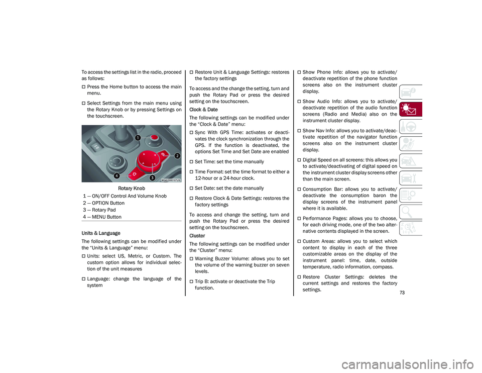
To access the settings list in the radio, proceed
as follows:
Press the Home button to access the main
menu.
Select Settings from the main menu using
the Rotary Knob or by pressing Settings on
the touchscreen.Rotary Knob
Units & Language
The following settings can be modified under
the “Units & Language” menu:
Units: select US, Metric, or Custom. The
custom option allows for individual selec -
tion of the unit measures
Language: change the language of the
system
Restore Unit & Language Settings: restores
the factory settings
To access and the change the setting, turn and
push the Rotary Pad or press the desired
setting on the touchscreen.
Clock & Date
The following settings can be modified under
the “Clock & Date” menu:
Sync With GPS Time: activates or deacti -
vates the clock synchronization through the
GPS. If the function is deactivated, the
options Set Time and Set Date are enabled
Set Time: set the time manually
Time Format: set the time format to either a
12-hour or a 24-hour clock.
Set Date: set the date manually
Restore Clock & Date Settings: restores the
factory settings
To access and change the setting, turn and
push the Rotary Pad or press the desired
setting on the touchscreen.
Cluster
The following settings can be modified under
the “Cluster” menu:
Warning Buzzer Volume: allows you to set
the volume of the warning buzzer on seven
levels.
Trip B: activate or deactivate the Trip
function.
Show Phone Info: allows you to activate/
deactivate repetition of the phone function
screens also on the instrument cluster
display.
Show Audio Info: allows you to activate/
deactivate repetition of the audio function
screens (Radio and Media) also on the
instrument cluster display.
Show Nav Info: allows you to activate/deac -
tivate repetition of the navigator function
screens also on the instrument cluster
display.
Digital Speed on all screens: this allows you
to activate/deactivating of digital speed on
the instrument cluster display screens other
than the main screen.
Consumption Bar: allows you to activate/
deactivate the consumption baron the
display screens of the instrument panel
where it is available.
Performance Pages: allows you to choose,
for each driving mode, one of the two alter -
native contents displayed in the screen.
Custom Areas: allows you to select which
content to display in each of the three
customizable areas on the display of the
instrument panel: time, date, outside
temperature, radio information, compass.
Restore Cluster Settings: deletes the
current settings and restores the factory
settings.
1 — ON/OFF Control And Volume Knob
2 — OPTION Button
3 — Rotary Pad
4 — MENU Button
21_GU_OM_EN_USC_t.book Page 73