2021 ALFA ROMEO STELVIO tire pressure
[x] Cancel search: tire pressurePage 202 of 280
IN CASE OF EMERGENCY
200
To use the Tire Service Kit, proceed as follows:
1. Apply the Electric Park Brake.
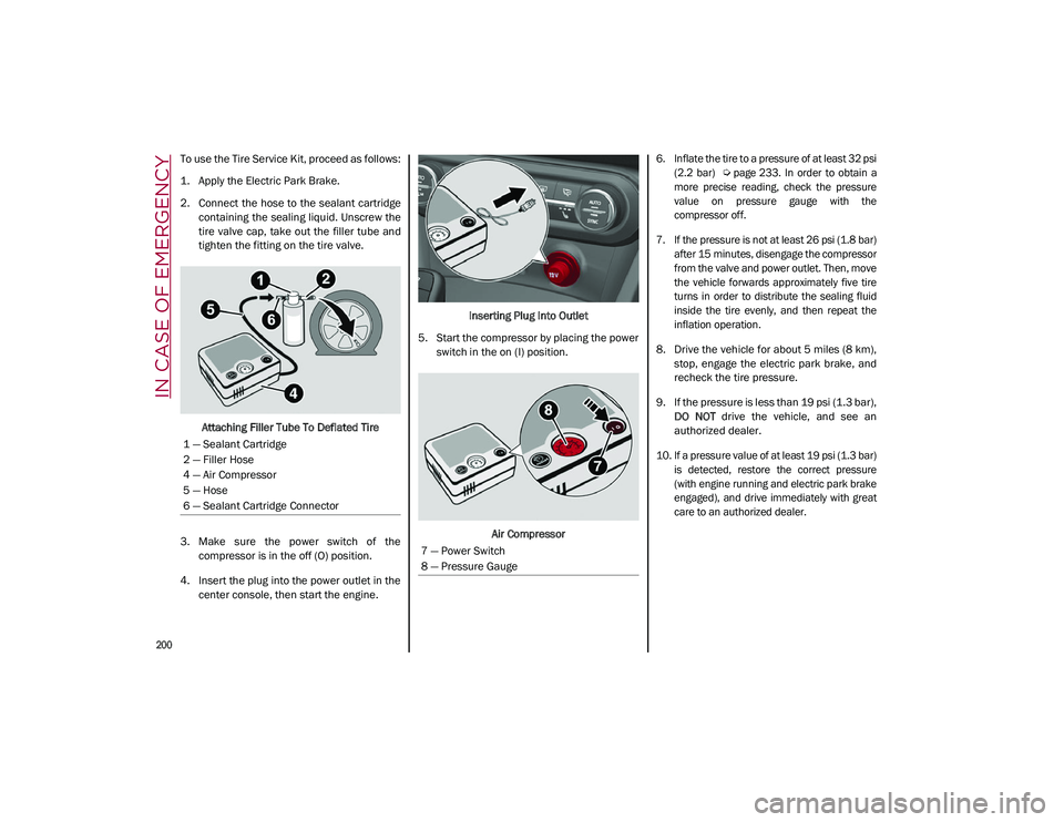
2. Connect the hose to the sealant cartridgecontaining the sealing liquid. Unscrew the
tire valve cap, take out the filler tube and
tighten the fitting on the tire valve.
Attaching Filler Tube To Deflated Tire
3. Make sure the power switch of the compressor is in the off (O) position.
4. Insert the plug into the power outlet in the center console, then start the engine. Inserting Plug Into Outlet
5. Start the compressor by placing the power switch in the on (I) position.
Air Compressor
6. Inflate the tire to a pressure of at least 32 psi
(2.2 bar)
Ú page 233. In order to obtain a
more precise reading, check the pressure
value on pressure gauge with the
compressor off.
7. If the pressure is not at least 26 psi (1.8 bar) after 15 minutes, disengage the compressor
from the valve and power outlet. Then, move
the vehicle forwards approximately five tire
turns in order to distribute the sealing fluid
inside the tire evenly, and then repeat the
inflation operation.
8. Drive the vehicle for about 5 miles (8 km), stop, engage the electric park brake, and
recheck the tire pressure.
9. If the pressure is less than 19 psi (1.3 bar), DO NOT drive the vehicle, and see an
authorized dealer.
10. If a pressure value of at least 19 psi (1.3 bar) is detected, restore the correct pressure
(with engine running and electric park brake
engaged), and drive immediately with great
care to an authorized dealer.
1 — Sealant Cartridge
2 — Filler Hose
4 — Air Compressor
5 — Hose
6 — Sealant Cartridge Connector
7 — Power Switch
8 — Pressure Gauge
21_GU_OM_EN_USC_t.book Page 200
Page 203 of 280
201
11. Apply the adhesive label from the sealantbottle where it can be easily seen by the
driver as a reminder that the tire has been
treated with a Tire Service Kit, as well as
not to exceed the speed restriction for the
treated tire.
NOTE:
Only use original sealant cartridges, which can
be purchased at an authorized dealer.
Checking And Restoring Tire Pressure
The compressor can also be used to check
and, if necessary, restore the tire pressure.
Proceed as follows:
1. Make sure that the power switch is in the
O (off) position.
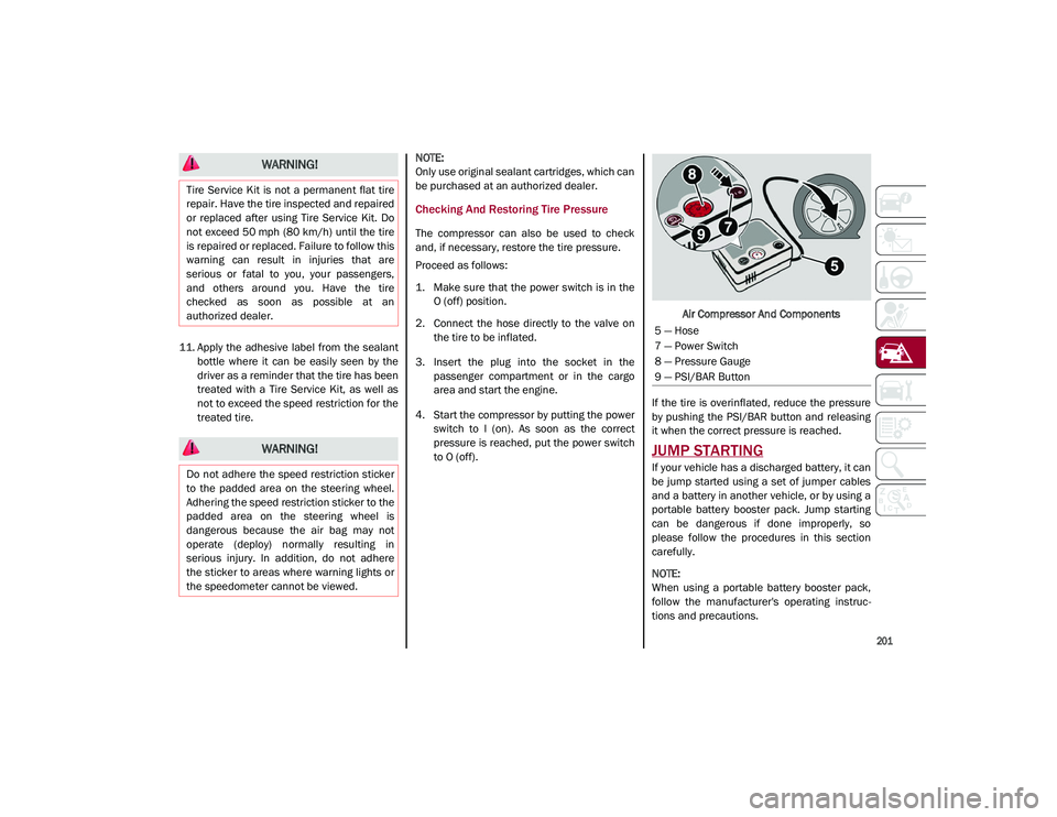
2. Connect the hose directly to the valve on the tire to be inflated.
3. Insert the plug into the socket in the passenger compartment or in the cargo
area and start the engine.
4. Start the compressor by putting the power switch to I (on). As soon as the correct
pressure is reached, put the power switch
to O (off). Air Compressor And Components
If the tire is overinflated, reduce the pressure
by pushing the PSI/BAR button and releasing
it when the correct pressure is reached.
JUMP STARTING
If your vehicle has a discharged battery, it can
be jump started using a set of jumper cables
and a battery in another vehicle, or by using a
portable battery booster pack. Jump starting
can be dangerous if done improperly, so
please follow the procedures in this section
carefully.
NOTE:
When using a portable battery booster pack,
follow the manufacturer's operating instruc -
tions and precautions.
WARNING!
Tire Service Kit is not a permanent flat tire
repair. Have the tire inspected and repaired
or replaced after using Tire Service Kit. Do
not exceed 50 mph (80 km/h) until the tire
is repaired or replaced. Failure to follow this
warning can result in injuries that are
serious or fatal to you, your passengers,
and others around you. Have the tire
checked as soon as possible at an
authorized dealer.
WARNING!
Do not adhere the speed restriction sticker
to the padded area on the steering wheel.
Adhering the speed restriction sticker to the
padded area on the steering wheel is
dangerous because the air bag may not
operate (deploy) normally resulting in
serious injury. In addition, do not adhere
the sticker to areas where warning lights or
the speedometer cannot be viewed.
5 — Hose
7 — Power Switch
8 — Pressure Gauge
9 — PSI/BAR Button
21_GU_OM_EN_USC_t.book Page 201
Page 210 of 280
208
SERVICING AND MAINTENANCE
Correct servicing permits the performance of
the vehicle to be maintained over time, as well
as limited running costs and safeguarding the
efficiency of the safety systems.
SCHEDULED SERVICING
Correct servicing is crucial for guaranteeing a
long life for the vehicle under the best condi-
tions.
For this reason, Alfa Romeo has planned a
series of checks and services for your vehicle
at fixed intervals based on distance and time,
as described in the Scheduled Servicing Plan.
Before each service, it is always necessary to
carefully follow the instructions in the Sched -
uled Servicing Plan (e.g. periodically check
level of fluids, tire pressure, etc.).
Scheduled Servicing is offered by an autho -
rized dealer according to a set time schedule.
If, during each operation, in addition to the
ones scheduled, the need arises for further
replacements or repairs, these may be carried
out with the owner’s explicit consent only.
NOTE:
Scheduled Servicing intervals are required by
the manufacturer. Failure to have them
carried out may invalidate the New Vehicle
Limited Warranty.
You are advised to inform an authorized
dealer of any small operating irregularities
without waiting for the next service.
Periodic Checks
Every month or every 620 miles (1,000 km) or
before long trips check and, if necessary, top
off:
Engine coolant level.
Brake fluid level (if insufficient, see an
authorized dealer as soon as possible).
Windshield washer fluid level.
Tire inflation pressure and condition.
Operation of lighting system (headlights,
direction indicators, hazard warning lights,
etc.).
Operation of windshield washing/wiping
system and positioning/wear of wiper
blades.
Inspect the CV/Universal joints.
Oil consumption of the engine depends on
conditions and driving style. For this reason,
the engine oil level must be checked every
1,860 miles (3,000 km), and top off if neces -
sary; for further information
Ú
page 215.
Heavy Usage Of The Vehicle
If the vehicle is used under one of the following
conditions:
Dusty roads.
Short, repeated journeys less than 4 miles
(7 km) at sub-zero outside temperatures.
Engine often idling or driving long distances
at low speeds or long periods of inactivity.
In the event of a long period of inactivity.
The following checks must be carried out more
often than indicated in the Scheduled
Servicing Plan:
Check cleanliness of hood and liftgate
locks, cleanliness and lubrication of
linkage.
Visually inspect conditions of: engine, trans -
mission, pipes and hoses (exhaust/fuel
system/brakes) and rubber elements
(sleeves/bushes, etc.).
Check battery charge and battery fluid level
(electrolyte).
Visually inspect conditions of the accessory
drive belts.
Check and, if necessary, change engine oil
and replace oil filter.
Check and, if necessary, replace cabin air
filter.
Check and, if necessary, replace air cleaner.
Severe Duty All Models
Change engine oil at 4,000 miles (6,500 km)
if the vehicle is operated in a dusty and
off-road environment or is operated predomi -
nately at idle or only very low engine RPM. This
type of vehicle use is considered Severe Duty.
21_GU_OM_EN_USC_t.book Page 208
Page 211 of 280
209
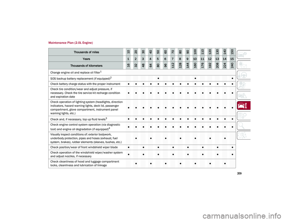
Maintenance Plan (2.0L Engine)
Thousands of miles102030405060708090100110120130140150
Years123456789101112131415
Thousands of kilometers163248648096112128144160176192208224240
Change engine oil and replace oil filter1
SOS backup battery replacement (if equipped)
2●●●
Check battery charge status with the proper instrument
●●●●●●●●●●●●●●●
Check tire condition/wear and adjust pressure, if
necessary. Check the tire service kit recharge condition
and expiration date
●●●●●●●●●●●●●●●
Check operation of lighting system (headlights, direction
indicators, hazard warning lights, deck lid, passenger
compartment, glove compartment, instrument panel
warning lights, etc.)
●●●●●●●●●●●●●●●
Check and, if necessary, top up fluid levels
3●●●●●●●●●●●●●●●
Check engine control system operation (via diagnostic
tool) and engine oil degradation (if equipped)
4●●●●●●●●●●●●●●●
Visually inspect conditions of: exterior bodywork,
underbody protection, pipes and hoses (exhaust, fuel
system, brakes), rubber elements (sleeves, bushes, etc.)
●●●●●●●
Check position/wear of front windshield wiper blade●●●●●●●●
Check operation of the windshield wiper/washer system
and adjust nozzles, if necessary
●●●●●●●●
Check cleanliness of hood and luggage compartment
locks, cleanliness and lubrication of linkage
●●●●●●●
21_GU_OM_EN_USC_t.book Page 209
Page 214 of 280
SERVICING AND MAINTENANCE
212
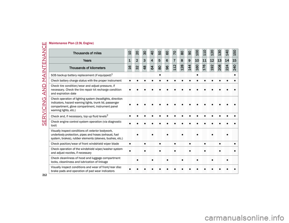
Maintenance Plan (2.9L Engine)
Thousands of miles102030405060708090100110120130140150
Years123456789101112131415
Thousands of kilometers163248648096112128144160176192208224240
SOS backup battery replacement (if equipped)1●●●
Check battery charge status with the proper instrument
●●●●●●●●●●●●●●●
Check tire condition/wear and adjust pressure, if
necessary. Check the tire repair kit recharge condition
and expiration date
●●●●●●●●●●●●●●●
Check operation of lighting system (headlights, direction
indicators, hazard warning lights, trunk lid, passenger
compartment, glove compartment, instrument panel
warning lights, etc.)
●●●●●●●●●●●●●●●
Check and, if necessary, top up fluid levels
2●●●●●●●●●●●●●●●
Check engine control system operation (via diagnostic
tool)
●●●●●●●●●●●●●●●
Visually inspect conditions of: exterior bodywork,
underbody protection, pipes and hoses (exhaust, fuel
system, brakes), rubber elements (sleeves, bushes, etc.)
●●●●●●●
Check position/wear of front windshield wiper blade●●●●●●●●
Check operation of the windshield wiper/washer system
and adjust nozzles, if necessary
●●●●●●●●
Check cleanliness of hood and luggage compartment
locks, cleanliness and lubrication of linkage
●●●●●●●
Visually inspect conditions and wear of front/rear disc
brake pads and operation of pad wear indicators●●●●●●●●●●●●●●●
21_GU_OM_EN_USC_t.book Page 212
Page 235 of 280
233
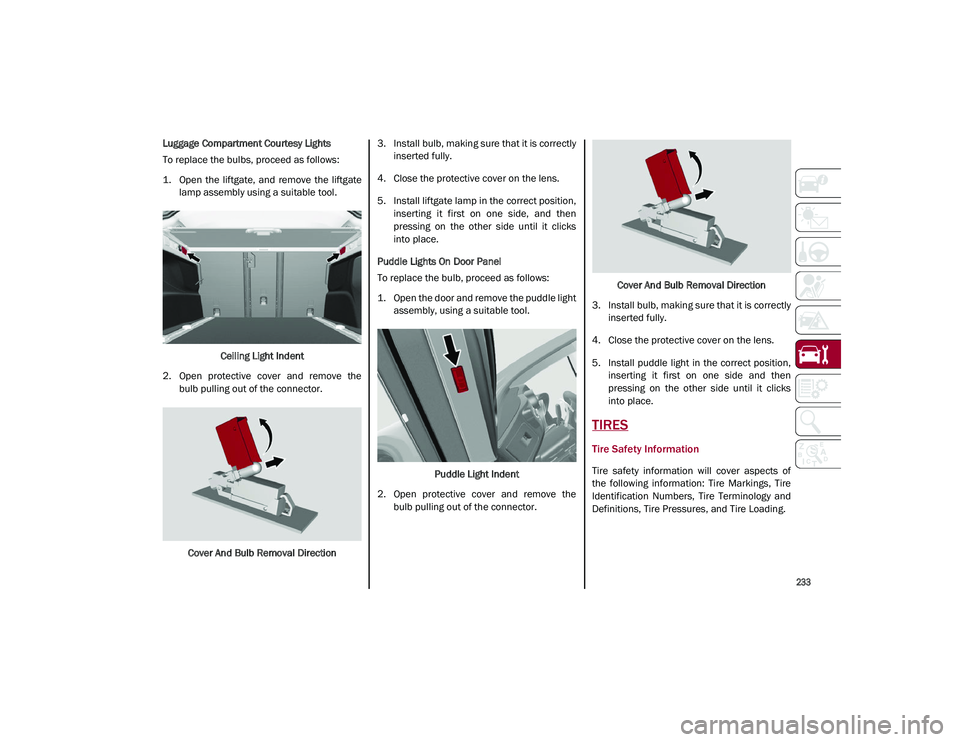
Luggage Compartment Courtesy Lights
To replace the bulbs, proceed as follows:
1. Open the liftgate, and remove the liftgatelamp assembly using a suitable tool.
Ceiling Light Indent
2. Open protective cover and remove the bulb pulling out of the connector.
Cover And Bulb Removal Direction 3. Install bulb, making sure that it is correctly
inserted fully.
4. Close the protective cover on the lens.
5. Install liftgate lamp in the correct position, inserting it first on one side, and then
pressing on the other side until it clicks
into place.
Puddle Lights On Door Panel
To replace the bulb, proceed as follows:
1. Open the door and remove the puddle light assembly, using a suitable tool.
Puddle Light Indent
2. Open protective cover and remove the bulb pulling out of the connector. Cover And Bulb Removal Direction
3. Install bulb, making sure that it is correctly inserted fully.
4. Close the protective cover on the lens.
5. Install puddle light in the correct position, inserting it first on one side and then
pressing on the other side until it clicks
into place.
TIRES
Tire Safety Information
Tire safety information will cover aspects of
the following information: Tire Markings, Tire
Identification Numbers, Tire Terminology and
Definitions, Tire Pressures, and Tire Loading.
21_GU_OM_EN_USC_t.book Page 233
Page 236 of 280
SERVICING AND MAINTENANCE
234
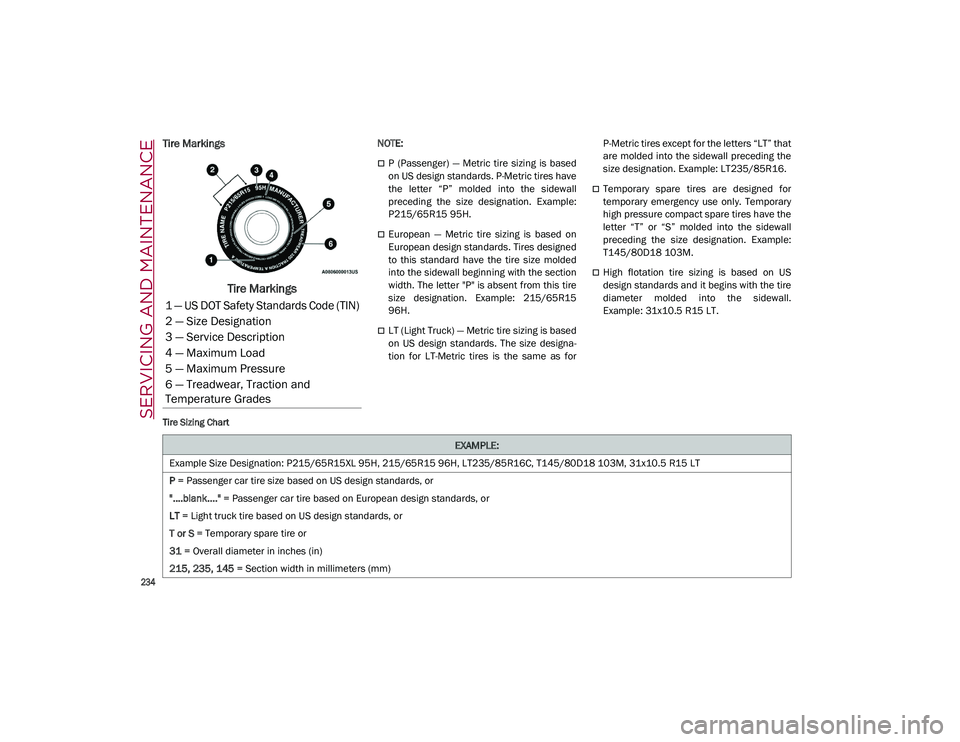
Tire Markings
Tire Markings
NOTE:
P (Passenger) — Metric tire sizing is based
on US design standards. P-Metric tires have
the letter “P” molded into the sidewall
preceding the size designation. Example:
P215/65R15 95H.
European — Metric tire sizing is based on
European design standards. Tires designed
to this standard have the tire size molded
into the sidewall beginning with the section
width. The letter "P" is absent from this tire
size designation. Example: 215/65R15
96H.
LT (Light Truck) — Metric tire sizing is based
on US design standards. The size designa-
tion for LT-Metric tires is the same as for P-Metric tires except for the letters “LT” that
are molded into the sidewall preceding the
size designation. Example: LT235/85R16.
Temporary spare tires are designed for
temporary emergency use only. Temporary
high pressure compact spare tires have the
letter “T” or “S” molded into the sidewall
preceding the size designation. Example:
T145/80D18 103M.
High flotation tire sizing is based on US
design standards and it begins with the tire
diameter molded into the sidewall.
Example: 31x10.5 R15 LT.
Tire Sizing Chart
1 — US DOT Safety Standards Code (TIN)
2 — Size Designation
3 — Service Description
4 — Maximum Load
5 — Maximum Pressure
6 — Treadwear, Traction and
Temperature Grades
EXAMPLE:
Example Size Designation: P215/65R15XL 95H, 215/65R15 96H, LT235/85R16C, T145/80D18 103M, 31x10.5 R15 LT
P = Passenger car tire size based on US design standards, or
"....blank...." = Passenger car tire based on European design standards, or
LT = Light truck tire based on US design standards, or
T or S = Temporary spare tire or
31 = Overall diameter in inches (in)
215, 235, 145 = Section width in millimeters (mm)
21_GU_OM_EN_USC_t.book Page 234
Page 237 of 280
235
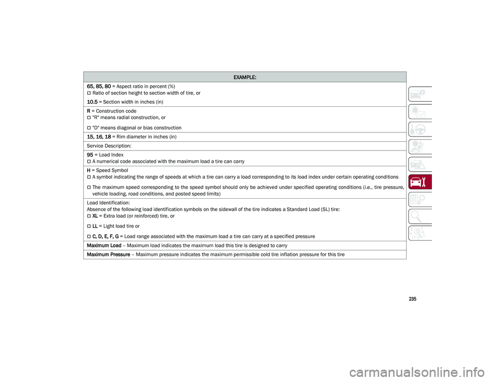
65, 85, 80 = Aspect ratio in percent (%)
Ratio of section height to section width of tire, or
10.5 = Section width in inches (in)
R = Construction code
"R" means radial construction, or
"D" means diagonal or bias construction
15, 16, 18 = Rim diameter in inches (in)
Service Description:
95 = Load Index
A numerical code associated with the maximum load a tire can carry
H = Speed Symbol
A symbol indicating the range of speeds at which a tire can carry a load corresponding to its load index under certain operating conditions
The maximum speed corresponding to the speed symbol should only be achieved under specified operating conditions (i.e., tire pressure,
vehicle loading, road conditions, and posted speed limits)
Load Identification:
Absence of the following load identification symbols on the sidewall of the tire indicates a Standard Load (SL) tire:
XL = Extra load (or reinforced) tire, or
LL = Light load tire or
C, D, E, F, G = Load range associated with the maximum load a tire can carry at a specified pressure
Maximum Load – Maximum load indicates the maximum load this tire is designed to carry
Maximum Pressure – Maximum pressure indicates the maximum permissible cold tire inflation pressure for this tire
EXAMPLE:
21_GU_OM_EN_USC_t.book Page 235