2021 ALFA ROMEO STELVIO tire pressure
[x] Cancel search: tire pressurePage 151 of 280
149
Panic Brake Assist (PBA) System
The PBA system is designed to improve the
vehicle’s braking capacity during emergency
braking.
The system detects emergency braking by
monitoring the speed and force with which the
brake pedal is pressed, and consequently
applies the optimal brake pressure. This can
reduce the braking distance: the PBA system
therefore complements the ABS.
Maximum assistance from the PBA system is
obtained by pressing the brake pedal very
quickly. In addition, the brake pedal should be
pressed continuously during braking, avoiding
intermittent presses, to get the most out of thesystem. Do not reduce pressure on the brake
pedal until braking is no longer necessary.
The PBA system is deactivated when the brake
pedal is released.Traction Control System (TCS)
The TCS automatically operates in the event of
slipping, loss of grip on wet roads (hydro
-
planing), and acceleration on one or both drive
wheels on roads that are slippery, snowy, icy,
etc. Depending on the slipping conditions, two
different control systems are activated:
If the slipping involves both drive wheels,
the system intervenes, reducing the power
transmitted by the engine.
If the slipping only involves one of the drive
wheels, the Brake Limited Differential (BLD)
function is activated, automatically braking the wheel which is slipping (the behavior of
a self-locking differential is simulated). This
will increase the engine torque transferred
to the wheel which isn't slipping.
System Intervention
The intervention of the system is indicated by
the flashing of the ESC warning light on the
instrument panel, to inform the driver that the
vehicle stability and grip are critical.
AUXILIARY DRIVING SYSTEMS
The following auxiliary driving systems are
available in this vehicle:
Blind Spot Monitoring (BSM) — if equipped
Active Blind Spot Assist (ABSA) — if
equipped
Forward Collision Warning Plus (FCW+)
Tire Pressure Monitoring System (TPMS)
The vehicle may also be fitted with the
following driving assistance systems:
Driver Attention Assist (DAA)
Lane Departure Warning (LDW)
Lane Keeping Assist (LKA)
Highway Assist System (HAS)
Traffic Jam Assist (TJA)
Adaptive Cruise Control (ACC)
Intelligent Speed Control (ISC)
Traffic Sign Recognition (TSR)
WARNING!
There may be situations where the Hill Start
Assist (HSA) will not activate and slight
rolling may occur, such as on minor hills or
with a loaded vehicle, or while pulling a
trailer. HSA is not a substitute for active
driving involvement. It is always the driver’s
responsibility to be attentive to distance to
other vehicles, people, and objects, and
most importantly brake operation to ensure
safe operation of the vehicle under all road
conditions. Your complete attention is
always required while driving to maintain
safe control of your vehicle. Failure to follow
these warnings can result in a collision or
serious personal injury.
WARNING!
The Panic Brake Assist (PBA) cannot
prevent the natural laws of physics from
acting on the vehicle, nor can it increase
the traction afforded by prevailing road
conditions. PBA cannot prevent collisions,
including those resulting from excessive
speed in turns, driving on very slippery
surfaces, or hydroplaning. The capabilities
of a PBA-equipped vehicle must never be
exploited in a reckless or dangerous
manner, which could jeopardize the user's
safety or the safety of others.
21_GU_OM_EN_USC_t.book Page 149
Page 163 of 280
161
Tire Pressure Monitoring System (TPMS)
The vehicle is equipped with a Tire Pressure
Monitoring System (TPMS) that sends the
inflation pressure information of each tire to
the control unit, and will signal the driver in the
event of insufficient tire pressure.
The TPMS uses wireless technology with wheel
rim mounted electronic sensors to monitor tire
pressure levels. Sensors, mounted to each
wheel as part of the valve stem, transmit tire
pressure readings to the receiver module.
Tire pressure will vary with temperature by
approximately 1 psi (7 kPa) for every 12°F
(6.5°C). This means that when the outside
temperature decreases, the tire pressure will
also decrease. Tire pressure should always be
set based on cold inflation tire pressure. This
is defined as the tire pressure after the vehicle
has not been driven for at least three hours, or
driven less than 1 mile (1.6 km) after a three
hour period. The cold tire inflation pressure
must not exceed the maximum inflation pres-
sure molded into the tire sidewall. The tire
pressure will also increase as the vehicle is
driven. This is normal, and there should be no
adjustment for this increased pressure.
See
Ú
page 233 for information on how to
properly inflate the vehicle’s tires.
The TPMS will signal the driver if pressure falls
below the warning limit for any reason,
including the effects of low temperature and
normal loss of pressure from the tire. The TPMS will stop indicating insufficient tire
pressure when pressure is equal to or greater
than the prescribed cold inflation level. There
-
fore, if insufficient tire pressure is indicated by
the ( ) warning light displaying in the instru -
ment cluster, increase the inflation pressure
up to the prescribed cold inflation value.
The system will automatically update, and the
TPMS Warning Light will turn off once the
system receives the updated tire pressures.
The vehicle may need to be driven for up to
20 minutes above 15 mph (24 km/h) in order
for the TPMS to receive this information.
NOTE:
The TPMS cannot indicate sudden tire pres -
sure drops (e.g. if a tire bursts). In this case,
proceed with caution and avoid abrupt
steering.
Operating Example
For example, your vehicle may have a recom -
mended cold (parked for more than three
hours) placard pressure of 33 psi (227 kPa). If
the ambient temperature is 68°F (20°C), and
the measured tire pressure is 28 psi (193 kPa),
a temperature drop to 20°F (-7°C) will
decrease the tire pressure to approximately
24 psi (165 kPa). This tire pressure is low
enough to turn on the “Tire Pressure Monitoring
Warning Light.” Driving the vehicle may cause
the tire pressure to rise to approximately 28 psi
(193 kPa), but the TPMS Warning Light will still
be on. In this situation, the TPMS Warning Light
WARNING!
The system has not been designed to
prevent impacts and cannot detect
possible conditions leading to an accident
in advance. Failure to take into account
this warning may lead to serious or fatal
injuries.
The system may activate, assessing the
trajectory of the vehicle, for the presence
of reflecting metal objects different from
other vehicles, such as safety barriers,
road signs, barriers before parking lots,
tollgates, level crossings, gates, railways,
objects near road constructions sites or
higher than the vehicle (e.g. a fly-over). In
the same way, the system may intervene
inside multi-story parking lots or tunnels,
or due to a glare on the road surface.
These possible activations are a conse -
quence of the real driving scenario
coverage by the system and must not be
regarded as faults.
The system has been designed for road
use only. If the vehicle is driven on a track,
the system must be deactivated to avoid
unnecessary warnings. Automatic deacti -
vation is signaled by the dedicated
warning light/symbol switching on in the
instrument panel
Ú
page 74.
21_GU_OM_EN_USC_t.book Page 161
Page 164 of 280
SAFETY
162
will turn off only after the tires are inflated to the
vehicle’s recommended cold placard pressure
value.Insufficient Tire Pressure Indication
If an insufficient pressure value is detected on
one or more tires, the warning light in the
instrument cluster will display alongside the
dedicated messages, the system will highlight
the tire or tires with insufficient pressure
graphically, and an acoustic signal will be
emitted.
In this case, stop the vehicle, check the infla
-
tion pressure of each tire, and inflate the
necessary tire or tires to the correct cold infla -
tion pressure value, shown on the display or in
the dedicated TPMS menu.
TPMS Temporarily Disabled:
TPMS Check Message
When a system fault is detected, the TPMS
Warning Light will flash on and off for 75 seconds,
and then remain on solid. The system fault will
also sound a chime. If the ignition is cycled, this
sequence will repeat, provided that the system
fault still exists. The TPMS Warning Light will turn
off when the fault condition no longer exists. A
system fault can occur due to any of the
following:
Jamming due to electronic devices or
driving next to facilities emitting the same
radio frequencies as the TPMS sensors.
Installing some form of aftermarket window
tinting that affects radio wave signals.
Packed snow or ice around the wheels or
wheel housings.
Using tire chains on the vehicle.
Using wheels/tires not equipped with TPMS
sensors.
After the punctured tire has been repaired
with the original tire sealant contained in the
Tire Kit, the previous condition must be
restored so that the warning light is off
during normal driving.
TPMS Deactivation
The TPMS can be deactivated by replacing all
four wheel and tire assemblies (road tires)
with wheel and tire assemblies that do not
have TPMS sensors, such as when installing
winter wheel and tire assemblies on your
vehicle.
To deactivate the TPMS, first replace all four
wheel and tire assemblies (road tires) with tires
not equipped with Tire Pressure Monitoring
System (TPMS) sensors. Then, drive the vehicle
for 20 minutes above 15 mph (24 km/h). The
TPMS will chime, the TPMS Warning Light will
flash on and off for 75 seconds and then
remain on. The instrument cluster will display
the “SERVICE TPM SYSTEM” message and then
display dashes (--) in place of the pressure
values.
Beginning with the next ignition switch cycle,
the TPMS will no longer chime or display the
“SERVICE TPM SYSTEM” message in the
instrument cluster. Instead, dashes (--) will
remain in place of the pressure values.
CAUTION!
The TPMS has been optimized for the orig -
inal equipment tires and wheels. TPMS
pressures and warning have been estab -
lished for the tire size equipped on your
vehicle. Undesirable system operation or
sensor damage may result when using
replacement equipment that is not of the
same size, type, and/or style. The TPMS
sensor is not designed for use on after -
market wheels and may contribute to a
poor overall system performance or
sensor damage. Customers are encour -
aged to use OEM wheels to assure proper
TPMS feature operation.
Using aftermarket tire sealants may cause
the Tire Pressure Monitoring System
(TPMS) sensor to become inoperable.
After using an aftermarket tire sealant it is
recommended that you take your vehicle
to an authorized dealer to have your
sensor function checked.
After inspecting or adjusting the tire pres -
sure always reinstall the valve stem cap.
This will prevent moisture and dirt from
entering the valve stem, which could
damage the TPMS sensor.
21_GU_OM_EN_USC_t.book Page 162
Page 165 of 280
163
To reactivate the TPMS, replace all four wheel
and tire assemblies (road tires) with tires
equipped with TPMS sensors. Then, drive the
vehicle for up to 20 minutes above 15 mph
(24 km/h). The TPMS will chime, the TPMS
Warning Light will flash on and off for 75
seconds and then turn off. The instrument
cluster will display the “SERVICE TPM
SYSTEM” message and then display pressure
values in place of the dashes. On the next igni-
tion switch cycle the “SERVICE TPM SYSTEM”
message will no longer be displayed, as long
as no system fault exists.
NOTE:
The TPMS is not intended to replace normal
tire care and maintenance, or to provide
warning of a tire failure or condition.
The TPMS should not be used as a tire pres -
sure gauge while adjusting your tire pres -
sure.
Driving on a significantly underinflated tire
will cause the tire to overheat, and can lead
to tire failure. Underinflation also reduces
fuel efficiency and tire tread life, and may
affect the vehicle’s handling and stopping
ability.
The TPMS is not a substitute for proper tire
maintenance, and it is the driver’s responsi -
bility to maintain correct tire pressure using
an accurate tire pressure gauge, even if underinflation has not reached the level to
trigger illumination of the TPMS Warning
Light.
Seasonal temperature changes will affect
tire pressure, and the TPMS will monitor the
actual tire pressure in the tire
Ú
page 268.
OCCUPANT RESTRAINT
SYSTEMS
Some of the most important safety features in
your vehicle are the restraint systems:
Occupant Restraint Systems Features
Seat Belt Systems
Supplemental Restraint Systems (SRS) Air
Bags
Child Restraints
Some of the safety features described in this
section may be standard equipment on some
models, or may be optional equipment on
others. If you are not sure, ask an authorized
dealer.
Important Safety Precautions
Please pay close attention to the information
in this section. It tells you how to use your
restraint system properly, to keep you and
your passengers as safe as possible. Here are some simple steps you can take to
minimize the risk of harm from a deploying air
bag:
1. Children 12 years old and under should
always ride buckled up in the rear seat of
a vehicle with a rear seat.
2. A child who is not big enough to wear the vehicle seat belt properly must be secured
in the appropriate child restraint or
belt-positioning booster seat in a rear
seating position
Ú
page 178.
3. If a child from 2 to 12 years old (not in a rear-facing child restraint) must ride in the
front passenger seat, move the seat as far
back as possible and use the proper child
restraint
Ú
page 178.
4. Never allow children to slide the shoulder belt behind them or under their arm.
5. You should read the instructions provided with your child restraint to make sure that
you are using it properly.
6. All occupants should always wear their lap and shoulder belts properly.
7. The driver and front passenger seats should be moved back as far as practical
to allow the front air bags room to inflate.
8. Do not lean against the door or window. If your vehicle has side air bags, and deploy -
ment occurs, the side air bags will inflate
21_GU_OM_EN_USC_t.book Page 163
Page 192 of 280
SAFETY
190
(Continued)
(Continued)
Periodic Safety Checks You Should Make
Outside The Vehicle
Tires
Examine tires for excessive tread wear and
uneven wear patterns. Check for stones, nails,
glass, or other objects lodged in the tread or
sidewall. Inspect the tread for cuts and cracks.
Inspect sidewalls for cuts, cracks, and bulges.
Check the wheel nuts for tightness. Check the
tires (including spare) for proper cold inflation
pressure.
Lights
Have someone observe the operation of brake
lights and exterior lights while you work the controls. Check turn signal and high beam
indicator lights on the instrument panel.
Door Latches
Check for proper closing, latching, and locking.
Fluid Leaks
Check area under the vehicle after overnight
parking for fuel, coolant, oil, or other fluid
leaks. Also, if gasoline fumes are detected or if
fuel, or brake fluid leaks are suspected, the
cause should be located and corrected imme
-
diately.
Exhaust Gas
ONLY use the driver’s side floor mat on the
driver’s side floor area. To check for inter -
ference, with the vehicle properly parked
with the engine off, fully depress the
accelerator, the brake, and the clutch
pedal (if present) to check for interfer -
ence. If your floor mat interferes with the
operation of any pedal, or is not secure to
the floor, remove the floor mat from the
vehicle and place the floor mat in your
trunk.
ONLY use the passenger’s side floor mat
on the passenger’s side floor area.
ALWAYS make sure objects cannot fall or
slide into the driver’s side floor area when
the vehicle is moving. Objects can become
trapped under accelerator, brake, or
clutch pedals and could cause a loss of
vehicle control.
NEVER place any objects under the floor
mat (e.g., towels, keys, etc.). These
objects could change the position of the
floor mat and may cause interference with
the accelerator, brake, or clutch pedals.
WARNING! (Continued)
If the vehicle carpet has been removed
and re-installed, always properly attach
carpet to the floor and check the floor mat
fasteners are secure to the vehicle carpet.
Fully depress each pedal to check for
interference with the accelerator, brake,
or clutch pedals then re-install the floor
mats.
It is recommended to only use mild soap
and water to clean your floor mats. After
cleaning, always check your floor mat has
been properly installed and is secured to
your vehicle using the floor mat fasteners
by lightly pulling mat.
WARNING! (Continued)
WARNING!
Exhaust gases can injure or kill. They
contain carbon monoxide (CO), which is
colorless and odorless. Breathing it can
make you unconscious and can eventually
poison you. To avoid breathing (CO), follow
these safety tips:
Do not run the engine in a closed garage
or in confined areas any longer than
needed to move your vehicle in or out of
the area.
If you are required to drive with the trunk/lift -
gate/rear doors open, make sure that all
windows are closed and the climate control
BLOWER switch is set at high speed. DO NOT
use the recirculation mode.
21_GU_OM_EN_USC_t.book Page 190
Page 199 of 280

197
13. Rotate the extension lever clockwise untilthe round pin on the jack engages in the
hole in the lifting block located about
6 inches (15 cm) from the outside edge of
the body. The lifting points are marked by
triangles visible on the plastic body
panel.
Jacking Point Indicators
14. Raise the vehicle by turning the jack screw clockwise, using the swivel wrench. Raise
the vehicle only until the tire just clears the
surface and enough clearance is obtained
to install the compact spare tire. Minimum
tire lift provides maximum stability. 15. Remove the five wheel bolts and take the
wheel off.
16. Make sure the contact surfaces between compact spare tire and hub are clean so
that the fastening bolts will not come
loose.
17. Fit the compact spare tire by inserting the first wheel bolt for two threads into the
hole closest to the valve.
18. Take the wheel wrench and tighten the wheel bolts.
19. Inflate the compact spare tire by removing the cap from its inflation valve and
screwing on the compressor inflation hose
fitting. 20. Make sure that the switch on the
compressor is in the (off) O position, open
the liftgate and insert the plug into the
power socket in the cargo area, or on the
center console and start the engine. Place
the on/off switch in the (on) I position.
Attaching Compressor To Tire
21. Inflate the compact spare tire to a pres -
sure of 43.5 psi (3 bar).
NOTE:
If spare tire is overinflated, be sure to lower
the psi in the tire to the recommended amount
by using the deflation button on the air
compressor.
22. Operate the wheel wrench on the jack to lower the vehicle.
CAUTION!
Do not attempt to raise the vehicle by
jacking on locations other than those
indicated in the Jacking Instructions for this
vehicle.
WARNING!
Raising the vehicle higher than necessary
can make the vehicle less stable. It could
slip off the jack and hurt someone near it.
Raise the vehicle only enough to remove
the tire.
CAUTION!
Be sure to mount the spare tire with the
valve stem facing outward. The vehicle
could be damaged if the spare tire is
mounted incorrectly.
6 — Air Compressor
7 — Pressure Gauge
8 — Power Button
21_GU_OM_EN_USC_t.book Page 197
Page 200 of 280
IN CASE OF EMERGENCY
198
23. Remove the jack.
24. Use the wheel wrench to fully tighten thebolts, passing alternately from one bolt to
the diagonally opposite one.
To obtain a more accurate reading, it is advis -
able to check the pressure of the compact
spare tire on the pressure gauge with the
compressor off.
NOTE:
Do not stow the deflated tire in the compact
spare tire location.
The compressor was designed for inflating the
compact spare tire. Do not use it for inflating
mattresses, rafts, etc.
NOTE:
Spare tires are intended for temporary use
only.
Have the full-sized tire repaired or replaced, as
soon as possible.
TIRE SERVICE KIT — IF
EQUIPPED
Description
If a tire is punctured, you can make an emer -
gency repair using the Tire Service Kit located
in the rear storage area under the load plat -
form.
1. Stop the vehicle in a position where you can repair the tire safely. You should be as
far as possible from the side of the road,
and in a position that is not dangerous for
oncoming traffic. Turn on the Hazard
Warning Flashers, remove the safety
triangle from the luggage compartment,
and place it at a suitable distance from the
vehicle to make other drivers aware of
your presence.
2. Verify that the valve stem (on the wheel with the deflated tire) is in a position that
is near to the ground. This will allow the tire repair kit hoses to reach the valve stem
and keep the tire service kit flat on the
ground.
3. Place the gear selector in PARK (P).
4. Apply the electric park brake and turn the engine OFF.
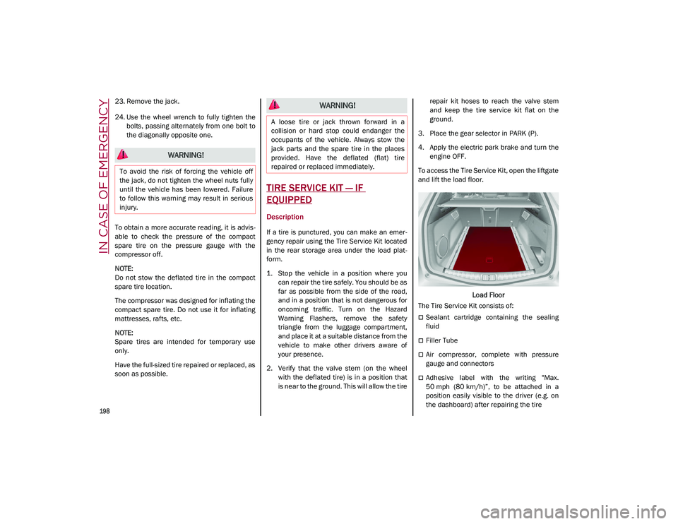
To access the Tire Service Kit, open the liftgate
and lift the load floor.
Load Floor
The Tire Service Kit consists of:
Sealant cartridge containing the sealing
fluid
Filler Tube
Air compressor, complete with pressure
gauge and connectors
Adhesive label with the writing "Max.
50 mph (80 km/h)”, to be attached in a
position easily visible to the driver (e.g. on
the dashboard) after repairing the tire
WARNING!
To avoid the risk of forcing the vehicle off
the jack, do not tighten the wheel nuts fully
until the vehicle has been lowered. Failure
to follow this warning may result in serious
injury.
WARNING!
A loose tire or jack thrown forward in a
collision or hard stop could endanger the
occupants of the vehicle. Always stow the
jack parts and the spare tire in the places
provided. Have the deflated (flat) tire
repaired or replaced immediately.
21_GU_OM_EN_USC_t.book Page 198
Page 201 of 280
199
(Continued)
An instruction pamphlet for reference in
prompt and correct use of the Tire Service
Kit, which must be then given to the
personnel dealing with the sealant-treated
tire
A pair of protective gloves
Some adapters, for inflating different
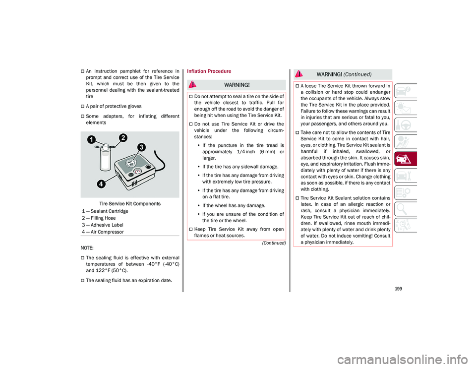
elementsTire Service Kit Components
NOTE:
The sealing fluid is effective with external
temperatures of between -40°F (-40°C)
and 122°F (50°C).
The sealing fluid has an expiration date.
Inflation Procedure
1 — Sealant Cartridge
2 — Filling Hose
3 — Adhesive Label
4 — Air Compressor
WARNING!
Do not attempt to seal a tire on the side of
the vehicle closest to traffic. Pull far
enough off the road to avoid the danger of
being hit when using the Tire Service Kit.
Do not use Tire Service Kit or drive the
vehicle under the following circum -
stances:
• If the puncture in the tire tread is
approximately 1/4 inch (6 mm) or
larger.
• If the tire has any sidewall damage.
• If the tire has any damage from driving
with extremely low tire pressure.
• If the tire has any damage from driving
on a flat tire.
• If the wheel has any damage.
• If you are unsure of the condition of
the tire or the wheel.
Keep Tire Service Kit away from open
flames or heat sources.
A loose Tire Service Kit thrown forward in
a collision or hard stop could endanger
the occupants of the vehicle. Always stow
the Tire Service Kit in the place provided.
Failure to follow these warnings can result
in injuries that are serious or fatal to you,
your passengers, and others around you.
Take care not to allow the contents of Tire
Service Kit to come in contact with hair,
eyes, or clothing. Tire Service Kit sealant is
harmful if inhaled, swallowed, or
absorbed through the skin. It causes skin,
eye, and respiratory irritation. Flush imme -
diately with plenty of water if there is any
contact with eyes or skin. Change clothing
as soon as possible, if there is any contact
with clothing.
Tire Service Kit Sealant solution contains
latex. In case of an allergic reaction or
rash, consult a physician immediately.
Keep Tire Service Kit out of reach of chil -
dren. If swallowed, rinse mouth immedi -
ately with plenty of water and drink plenty
of water. Do not induce vomiting! Consult
a physician immediately.
WARNING! (Continued)
21_GU_OM_EN_USC_t.book Page 199