2021 ALFA ROMEO STELVIO fuel
[x] Cancel search: fuelPage 57 of 280
55
Humidity Sensor
The Humidity Sensor helps prevent the
windows from fogging up. The AUTO function
(indicator illuminated) must be on for the
Humidity Sensor to function.
When outside temperature is low, the system
may turn the compressor on and turn air recir-
culation off for safer driving.
Stop/Start
The Stop/Start system shuts off the engine
when the vehicle speed is 0 mph (0 km/h), as
a fuel conservation measure.
In order to maintain comfort in the cabin, the
Stop/Start feature will not activate if any of the
following conditions exist:
The Climate Control system is in AUTO mode
(indicator illuminated), and the vehicle has
yet to reach the set temperature
The Climate Control system is in LO
maximum cooling
The Climate Control system is in HI
maximum heating
The Climate Control system is in the
MAX-DEF status
When the Stop/Start system is active, the
engine will restart if the inside temperature
changes significantly, or if the LO setting, or
MAX-DEF setting, is activated. With Stop/Start system on (engine is OFF), air
flow is reduced to keep the compartment
comfort conditions for longer.
Until the temperature drastically changes
within the cabin, the climate control system
will continue to maintain the temperature
while the engine is off. By deactivating the
Stop/Start system with the button (located
by the headlight switch), the climate control
system operates normally according to the
settings.
NOTE:
In harsh climate conditions, limit the use of
the Stop/Start system to prevent the
compressor from continuously switching on
and off. This will cause rapid misting of the
windows and the accumulation of humidity
in the passenger compartment.
When the Stop/Start system is on, the
climate control system will always take air in
from outside, reducing the probability of the
windows fogging up.
System Maintenance
In winter months, the Climate Control system
must be turned on at least once a month for
approximately 10 minutes.
Have the system inspected at an authorized
dealer before the summer.
INTERIOR STORAGE AND
EQUIPMENT
Glove Compartment
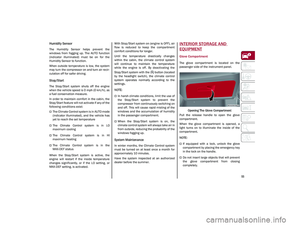
The glove compartment is located on the
passenger side of the instrument panel.
Opening The Glove Compartment
Pull the release handle to open the glove
compartment.
When the glove compartment is opened, a
light turns on to illuminate the inside of the
compartment.
NOTE:
If equipped with a lock, unlock the glove
compartment by placing the emergency key
in the lock on the handle.
Do not insert large objects that will prevent
the glove compartment from closing
completely.
21_GU_OM_EN_USC_t.book Page 55
Page 71 of 280
69
3. Instrument Cluster Display•The instrument cluster display features
a driver interactive display
Ú
page 69.
4. Fuel Gauge •The digital bar gauge shows the amount
of fuel in the tank.
• The fuel reserve/limited range
warning light turns on, a message is
displayed and there is an acoustic
signal when about 2.4 gallons (9 liters)
of fuel are left in the tank.
• The fuel pump symbol points to the
side of the vehicle where the fuel door is
located.
• P
roceeding further, the second white
notch will go off and the last one will become red, together with the indica-
tion "E" present at the bottom of the
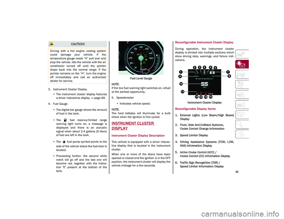
tank. Fuel
Level Gauge
NOTE:
If the low fuel warning light switches on, refuel
at the earliest opportunity.
5. Speedometer •Indicates vehicle speed.
NOTE:
The hard telltales will illuminate for a bulb
check when the ignition is first cycled.
INSTRUMENT CLUSTER
DISPLAY
Instrument Cluster Display Description
This vehicle is equipped with a driver interac -
tive display that is located in the instrument
cluster.
When one or more of the doors have been
opened or closed and the ignition is in the OFF
position, the instrument cluster will display the
vehicle mileage for a few seconds.
Reconfigurable Instrument Cluster Display
During operation, the instrument cluster
display is divided into multiple sections which
show driving data, warnings, and failure indi -
cations.
Instrument Cluster Display
Reconfigurable Display Items
1. External Lights (Low Beam/High Beam)Display
2. Front, Side Anti-Collision Systems, Cruise Control Change Information
3. Speed Limiter Display
4. Driving Assistance Systems (FCW, LDW, HAS) Information Display
5. Active Cruise Control (ACC) / Cruise Control (CC) Information Display
6. Traffic Sign Recognition (TSR) / Speed Limiter Information Display
CAUTION!
Driving with a hot engine cooling system
could damage your vehicle. If the
temperature gauge reads “H” pull over and
stop the vehicle. Idle the vehicle with the air
conditioner turned off until the pointer
drops back into the normal range. If the
pointer remains on the “H”, turn the engine
off immediately and call an authorized
dealer for service.
21_GU_OM_EN_USC_t.book Page 69
Page 72 of 280
GETTING TO KNOW YOUR INSTRUMENT PANEL
70
7. Traffic Sign Recognition (TSR) InformationDisplay
8. Time
9. External Temperature
10. Main Display: Vehicle Speed Display, Trip Computer Information, etc...
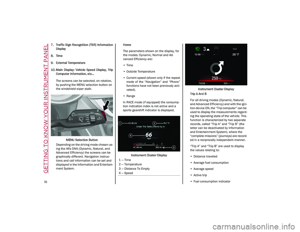
The screens can be selected, on rotation,
by pushing the MENU selection button on
the windshield wiper stalk.
MENU Selection Button
Depending on the driving mode chosen us -
ing the Alfa DNA (Dynamic, Natural, and
Advanced Efficiency) the screens can be
graphically different. Navigation instruc -
tions and call information can be set and
displayed in the Information and Entertain -
ment System. Home
The parameters shown on the display, for
the modes: Dynamic, Normal and Ad
-
vanced Efficiency are:
• Time
• Outside Temperature
• Current speed (shown only if the repeat
mode of the “Navigation” and “Phone”
functions have not been previously acti-
vated).
• Range
In RACE mode (if equipped) the consump -
tion indication index is not active and a
sports gearshift indicator is displayed.
Instrument Cluster Display Instrument Cluster Display
Trip A And B
For all driving modes (Dynamic, Natural,
and Advanced Efficiency) and with the igni -
tion device ON, the “Trip computer” can be
used to display the measurements regard -
ing the operating state of the vehicle. This
function is characterized by two separate
records, called “Trip A” and “Trip B” (the
latter can be deactivated by Information
and Entertainment System), where the
“complete missions” (journeys) are record -
ed in a reciprocally independent manner.
“Trip A” and “Trip B” are used to display
the values relating to:
• Distance traveled
• Average fuel consumption
• Average speed
• Active trip
• Fuel consumption indicator
1 — Time
2 — Temperature
3 — Distance To Empty
4 — Speed
21_GU_OM_EN_USC_t.book Page 70
Page 73 of 280
71
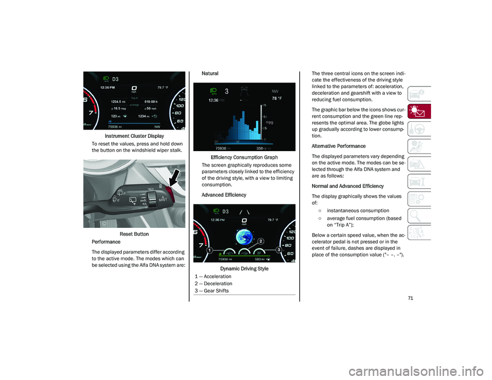
Instrument Cluster Display
To reset the values, press and hold down
the button on the windshield wiper stalk.
Reset Button
Performance
The displayed parameters differ according
to the active mode. The modes which can
be selected using the Alfa DNA system are: Natural
Efficiency Consumption Graph
The screen graphically reproduces some
parameters closely linked to the efficiency
of the driving style, with a view to limiting
consumption.
Advanced Efficiency
Dynamic Driving Style The three central icons on the screen indi
-
cate the effectiveness of the driving style
linked to the parameters of: acceleration,
deceleration and gearshift with a view to
reducing fuel consumption.
The graphic bar below the icons shows cur -
rent consumption and the green line rep -
resents the optimal area. The globe lights
up gradually according to lower consump -
tion.
Alternative Performance
The displayed parameters vary depending
on the active mode. The modes can be se -
lected through the Alfa DNA system and
are as follows:
Normal and Advanced Efficiency
The display graphically shows the values
of:
○ instantaneous consumption
○ average fuel consumption (based on “Trip A”);
Below a certain speed value, when the ac -
celerator pedal is not pressed or in the
event of failure, dashes are displayed in
place of the consumption value ("– –. –").
1 — Acceleration
2 — Deceleration
3 — Gear Shifts
21_GU_OM_EN_USC_t.book Page 71
Page 74 of 280
GETTING TO KNOW YOUR INSTRUMENT PANEL
72
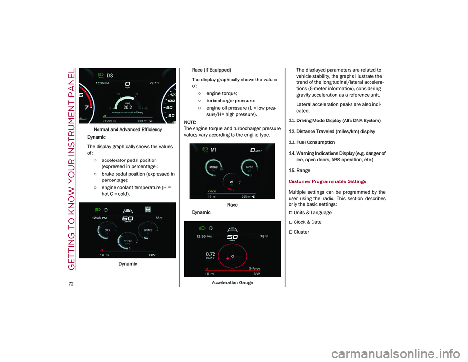
Normal and Advanced Efficiency
Dynamic
The display graphically shows the values
of: ○ accelerator pedal position (expressed in percentage);
○ brake pedal position (expressed in percentage);
○ engine coolant temperature (H = hot C = cold).
Dynamic Race (If Equipped)
The display graphically shows the values
of:
○ engine torque;
○ turbocharger pressure;
○ engine oil pressure (L = low pres -
sure/H= high pressure).
NOTE:
The engine torque and turbocharger pressure
values vary according to the engine type.
Race
Dynamic
Acceleration Gauge The displayed parameters are related to
vehicle stability, the graphs illustrate the
trend of the longitudinal/lateral accelera
-
tions (G-meter information), considering
gravity acceleration as a reference unit.
Lateral acceleration peaks are also indi -
cated.
11. Driving Mode Display (Alfa DNA System)
12. Distance Traveled (miles/km) display
13. Fuel Consumption
14. Warning Indications Display (e.g. danger of ice, open doors, ABS operation, etc.)
15. Range
Customer Programmable Settings
Multiple settings can be programmed by the
user using the radio. This section describes
only the basic settings:
Units & Language
Clock & Date
Cluster
21_GU_OM_EN_USC_t.book Page 72
Page 78 of 280
GETTING TO KNOW YOUR INSTRUMENT PANEL
76
required. However, the conventional brake
system will continue to operate normally if the
brake indicator light is not on.
If the ABS light is on, the brake system should
be serviced as soon as possible to restore the
benefits of Anti-Lock Brakes. If the ABS light
does not turn on when the ignition is placed in
the ON/RUN position, have the light inspected
by an authorized dealer.
Electronic Stability Control (ESC) Indicator
Light — If Equipped
When the ignition is cycled to ON, the
indicator light illuminates, but
should turn off as soon as the engine
is started.
ESC System Intervention : Intervention by the
system is indicated by the flashing of the indi -
cator light: it indicates that the vehicle is in crit -
ical stability and grip conditions.
ESC System Failure : If the indicator light does
not turn off, or if it stays on with the engine
running, a failure was found in the ESC
system.
Hill Start Assist System Failure : The illumina-
tion of the indicator light indicates a Hill Start
Assist system failure.
In these cases, contact an authorized dealer
as soon as possible.
Electronic Stability Control (ESC) OFF
Indicator Light — If Equipped
When the ignition is cycled to ON, the
indicator light illuminates, but
should turn off as soon as the engine
is started.
The indicator light illuminates to indicate that
some active safety systems have been
partially or totally deactivated
Ú
page 145.
When the active safety systems are reacti -
vated, the indicator light turns off.
Tire Pressure Low Warning Light
The indicator light will illuminate to
indicate that the tire pressure is
lower than the recommended value
and/or that slow pressure loss is
occurring. In these cases, optimal tire duration
and fuel consumption may not be guaranteed.
In any situation in which the message on the
display is “See Manual”
Ú
page 161.
Tire Pressure Monitoring System (TPMS)
Warning Light
The warning light switches on and a
message is displayed to indicate
that the tire pressure is lower than
the recommended value and/or that
slow pressure loss is occurring. In these cases,
optimal tire duration and fuel consumption
may not be guaranteed. Should one or more tires be in the condition
mentioned above, the display will show the
indications corresponding to each tire.
Each tire, including the spare (if provided),
should be checked monthly when cold and
inflated to the inflation pressure recom
-
mended by the vehicle manufacturer on the
vehicle placard or tire inflation pressure label.
If your vehicle has tires of a different size than
the size indicated on the vehicle placard or tire
inflation pressure label, you should determine
the proper tire inflation pressure for those
tires.
As an added safety feature, your vehicle has
been equipped with a TPMS that illuminates a
low tire pressure telltale when one or more of
your tires is significantly underinflated. Accord -
ingly, when the low tire pressure telltale illumi -
nates, you should stop and check your tires as
soon as possible, and inflate them to the
proper pressure. Driving on a significantly
underinflated tire causes the tire to overheat
and can lead to tire failure. Under inflation
CAUTION!
Do not continue driving with one or more
flat tires as handling may be compromised.
Stop the vehicle, avoiding sharp braking
and steering. If a tire puncture occurs,
repair immediately using the dedicated tire
repair kit and contact an authorized dealer
as soon as possible.
21_GU_OM_EN_USC_t.book Page 76
Page 79 of 280
77
also reduces fuel efficiency and tire tread life,
and may affect the vehicle’s handling and
stopping ability.
Please note that the TPMS is not a substitute
for proper tire maintenance, and it is the
driver’s responsibility to maintain correct tire
pressure, even if under inflation has not
reached the level to trigger illumination of the
TPMS low tire pressure telltale.
Your vehicle has also been equipped with a
TPMS malfunction indicator to indicate when
the system is not operating properly. The
TPMS malfunction indicator is combined with
the low tire pressure telltale. When the system
detects a malfunction, the telltale will flash for
approximately one minute and then remain
continuously illuminated. This sequence will
continue upon subsequent vehicle start-ups
as long as the malfunction exists. When the
malfunction indicator is illuminated, the
system may not be able to detect or signal low
tire pressure as intended. TPMS malfunctions
may occur for a variety of reasons, including
the installation of replacement or alternate
tires or wheels on the vehicle that prevent the
TPMS from functioning properly. Always check
the TPMS malfunction telltale after replacing
one or more tires or wheels on your vehicle to
ensure that the replacement or alternate tires
and wheels allow the TPMS to continue to
function properly.
Rear Fog Lights
The indicator illuminates when the
rear fog light is activated.
Engine Check/Malfunction Indicator Light
(MIL)
In normal conditions, when the igni-
tion is cycled to ON, the indicator
light illuminates, but it should turn
off as soon as the engine is started.
The operation of the indicator light may be
checked by the traffic police using specific
devices. Comply with the laws and regulations
of the country where you are driving. Under these conditions, the vehicle can
continue traveling at moderate speed but
without demanding excessive effort from the
engine or high speed. Prolonged use of the
vehicle with the indicator light on constantly
may cause damage. Contact an authorized
dealer as soon as possible.
Forward Collision Warning (FCW) System
This indicator light informs the driver
that the frontal collision alarm func
-
tion is not enabled.
Drive carefully and contact an authorized
dealer as soon as possible.
Fuel Reserve/Limited Range
The indicator light (or the symbol in
the display) illuminates when about
2.4 gallons (9 liters) of fuel is left in
the tank.
WARNING!
The TPMS has been optimized for the
original equipment tires and wheels. TPMS
pressures and warning have been
established for the tire size equipped on
your vehicle. Undesirable system operation
or sensor damage may result when using
replacement equipment that is not of the
same size, type, and/or style. Aftermarket
wheels can cause sensor damage. Using
aftermarket tire sealants may cause the
Tire Pressure Monitoring System (TPMS)
sensor to become inoperable. After using
an aftermarket tire sealant it is
recommended that you take your vehicle to
an authorized dealership to have your
sensor function checked.
CAUTION!
If, turning the ignition device to ON, the
warning light does not turn on or if it
turns on steadily or flashing when traveling
(on some versions together with the
message on the display), contact an
authorized dealer as soon as possible.
21_GU_OM_EN_USC_t.book Page 77
Page 82 of 280
GETTING TO KNOW YOUR INSTRUMENT PANEL
80
the oil level can be checked on the display
upon entering the vehicle and also by acti-
vating the “Oil level” function on the Informa -
tion and Entertainment System.
Contact an authorized dealer as soon as
possible.
Trunk Lid Not Properly Shut
The telltale turns on when the trunk
lid is not properly closed, along with
the icon, an image of the vehicle with
an open trunk lid appears on the
display.
A buzzer is heard when the trunk lid is open
and the vehicle is moving.
Close the trunk lid properly.
Amber Symbols
Engine Immobilizer Failure/Break-In
Attempt
Engine Immobilizer System Failure
The telltale will illuminate to report a
failure of the Engine Immobilizer
system. Break-In Attempt
The telltale will illuminate
when the ignition is cycled to ON position, to
indicate a possible break-in attempt detected
by the alarm system.
Electronic Key Not Recognized The telltale will
illuminate when the engine is started and the
electronic key is not recognized by the system.
Alarm System Failure The telltale will illumi -
nate to report an alarm system failure.
Contact an authorized dealer as soon as
possible.
Fuel Cut-Off Indicator Light
The telltale will illuminate after an
accident has occurred and the
system has shut the fuel off.
For reactivating the fuel cut-off system
Ú
page 163. If it is not possible to restore the
fuel supply, contact an authorized dealer.
Park Sensors System Failure
The telltale will illuminate when the
system has failed or is not available.
Contact an authorized dealer to have
the system checked.
Engine Oil Change Required — If Equipped
The telltale is illuminated only for a
limited time.
NOTE:
After the first indication, each time the engine
is started the symbol will continue to illumi
-
nate as described above until the oil is
changed.
If the telltale flashes, this does not mean that
there is a fault on the vehicle, rather it simply
reports that it is now necessary to change the oil
as a result of regular use of the vehicle. The dete -
rioration of engine oil is accelerated by using the
vehicle for short drives, preventing the engine
from reaching operating temperature.
Contact an authorized dealer as soon as
possible.Engine Oil Pressure Sensor Failure
The telltale will illuminate in the
event of engine oil pressure sensor
failure.
Contact an authorized dealer as soon as
possible.
CAUTION!
If the LOW ENGINE OIL PRESSURE symbol
switches on when driving, stop the engine
immediately and contact an authorized
dealer.
CAUTION!
Deteriorated engine oil should be replaced as
soon as possible after the symbol is switched
on, and never more than 500 miles (805 km)
after it first switches on. Failure to observe the
above may result in severe damage to the
engine and invalidate the New Vehicle Limited
Warranty. When this symbol comes on, it does
not mean that the level of engine oil is low, so if
it flashes you do not need to top up the engine
oil.
21_GU_OM_EN_USC_t.book Page 80