2021 ALFA ROMEO STELVIO change time
[x] Cancel search: change timePage 92 of 280
STARTING AND OPERATING
90
For the first 1,500 miles (2,414 km):
Do not participate in track events, sport
driving schools, or similar activities during
the first 1,500 miles (2,414 km).
NOTE:
Monitor engine oil with every refueling and add
if necessary. Oil and fuel consumption may be
higher through the first oil change interval.
ELECTRIC PARK BRAKE (EPB)
The EPB features a switch located on the
center console, a caliper with motor for each
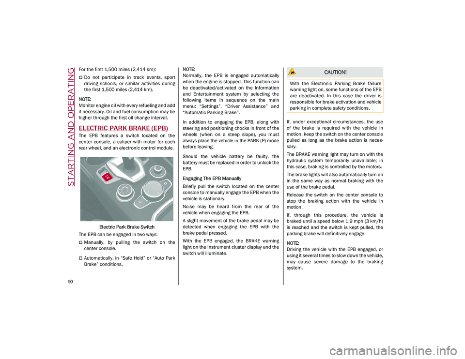
rear wheel, and an electronic control module.
Electric Park Brake Switch
The EPB can be engaged in two ways:
Manually, by pulling the switch on the
center console.
Automatically, in “Safe Hold” or “Auto Park
Brake” conditions.
NOTE:
Normally, the EPB is engaged automatically
when the engine is stopped. This function can
be deactivated/activated on the Information
and Entertainment system by selecting the
following items in sequence on the main
menu: “Settings”, “Driver Assistance” and
“Automatic Parking Brake”.
In addition to engaging the EPB, along with
steering and positioning chocks in front of the
wheels (when on a steep slope), you must
always place the vehicle in the PARK (P) mode
before leaving.
Should the vehicle battery be faulty, the
battery must be replaced in order to unlock the
EPB.
Engaging The EPB Manually
Briefly pull the switch located on the center
console to manually engage the EPB when the
vehicle is stationary.
Noise may be heard from the rear of the
vehicle when engaging the EPB.
A slight movement of the brake pedal may be
detected when engaging the EPB with the
brake pedal pressed.
With the EPB engaged, the BRAKE warning
light on the instrument cluster display and the
switch will illuminate.
If, under exceptional circumstances, the use
of the brake is required with the vehicle in
motion, keep the switch on the center console
pulled as long as the brake action is neces
-
sary.
The BRAKE warning light may turn on with the
hydraulic system temporarily unavailable; in
this case, braking is controlled by the motors.
The brake lights will also automatically turn on
in the same way as normal braking with the
use of the brake pedal.
Release the switch on the center console to
stop the braking action with the vehicle in
motion.
If, through this procedure, the vehicle is
braked until a speed below 1.9 mph (3 km/h)
is reached and the switch is kept pulled, the
parking brake will definitively engage.
NOTE:
Driving the vehicle with the EPB engaged, or
using it several times to slow down the vehicle,
may cause severe damage to the braking
system.
CAUTION!
With the Electronic Parking Brake failure
warning light on, some functions of the EPB
are deactivated. In this case the driver is
responsible for brake activation and vehicle
parking in complete safety conditions.
21_GU_OM_EN_USC_t.book Page 90
Page 108 of 280
STARTING AND OPERATING
106
To Accelerate For Passing
Press the accelerator as you would normally.
When the pedal is released, the vehicle will
return to the set speed.
Using Cruise Control On Hills
The transmission may downshift on hills to
maintain the vehicle set speed.
NOTE:
The Cruise Control system maintains speed up
and down hills. A slight speed change on
moderate hills is normal.
On steep hills, a greater speed loss or gain
may occur so it may be preferable to drive
without Cruise Control.
To Resume Speed
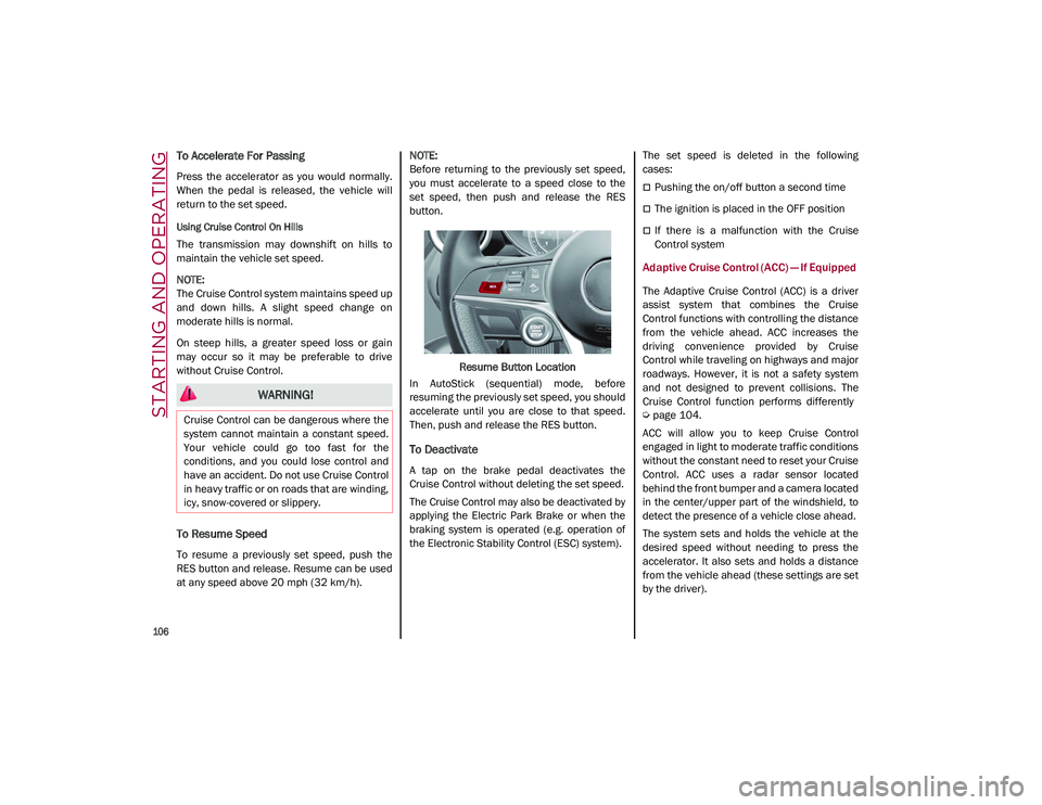
To resume a previously set speed, push the
RES button and release. Resume can be used
at any speed above 20 mph (32 km/h).
NOTE:
Before returning to the previously set speed,
you must accelerate to a speed close to the
set speed, then push and release the RES
button.
Resume Button Location
In AutoStick (sequential) mode, before
resuming the previously set speed, you should
accelerate until you are close to that speed.
Then, push and release the RES button.
To Deactivate
A tap on the brake pedal deactivates the
Cruise Control without deleting the set speed.
The Cruise Control may also be deactivated by
applying the Electric Park Brake or when the
braking system is operated (e.g. operation of
the Electronic Stability Control (ESC) system). The set speed is deleted in the following
cases:
Pushing the on/off button a second time
The ignition is placed in the OFF position
If there is a malfunction with the Cruise
Control system
Adaptive Cruise Control (ACC) — If Equipped
The Adaptive Cruise Control (ACC) is a driver
assist system that combines the Cruise
Control functions with controlling the distance
from the vehicle ahead. ACC increases the
driving convenience provided by Cruise
Control while traveling on highways and major
roadways. However, it is not a safety system
and not designed to prevent collisions. The
Cruise Control function performs differently
Ú
page 104.
ACC will allow you to keep Cruise Control
engaged in light to moderate traffic conditions
without the constant need to reset your Cruise
Control. ACC uses a radar sensor located
behind the front bumper and a camera located
in the center/upper part of the windshield, to
detect the presence of a vehicle close ahead.
The system sets and holds the vehicle at the
desired speed without needing to press the
accelerator. It also sets and holds a distance
from the vehicle ahead (these settings are set
by the driver).
WARNING!
Cruise Control can be dangerous where the
system cannot maintain a constant speed.
Your vehicle could go too fast for the
conditions, and you could lose control and
have an accident. Do not use Cruise Control
in heavy traffic or on roads that are winding,
icy, snow-covered or slippery.
21_GU_OM_EN_USC_t.book Page 106
Page 112 of 280
STARTING AND OPERATING
110
(Continued)
Setting The Distance Between Vehicles
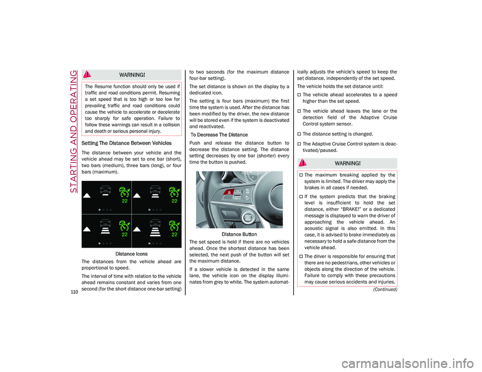
The distance between your vehicle and the
vehicle ahead may be set to one bar (short),
two bars (medium), three bars (long), or four
bars (maximum).Distance Icons
The distances from the vehicle ahead are
proportional to speed.
The interval of time with relation to the vehicle
ahead remains constant and varies from one
second (for the short distance one-bar setting) to two seconds (for the maximum distance
four-bar setting).
The set distance is shown on the display by a
dedicated icon.
The setting is four bars (maximum) the first
time the system is used. After the distance has
been modified by the driver, the new distance
will be stored even if the system is deactivated
and reactivated.
To Decrease The Distance
Push and release the distance button to
decrease the distance setting. The distance
setting decreases by one bar (shorter) every
time the button is pushed.
Distance Button
The set speed is held if there are no vehicles
ahead. Once the shortest distance has been
selected, the next push of the button will set
the maximum distance.
If a slower vehicle is detected in the same
lane, the vehicle icon on the display illumi -
nates from grey to white. The system automat -ically adjusts the vehicle’s speed to keep the
set distance, independently of the set speed.
The vehicle holds the set distance until:
The vehicle ahead accelerates to a speed
higher than the set speed.
The vehicle ahead leaves the lane or the
detection field of the Adaptive Cruise
Control system sensor.
The distance setting is changed.
The Adaptive Cruise Control system is deac
-
tivated/paused.
WARNING!
The Resume function should only be used if
traffic and road conditions permit. Resuming
a set speed that is too high or too low for
prevailing traffic and road conditions could
cause the vehicle to accelerate or decelerate
too sharply for safe operation. Failure to
follow these warnings can result in a collision
and death or serious personal injury.
WARNING!
The maximum breaking applied by the
system is limited. The driver may apply the
brakes in all cases if needed.
If the system predicts that the braking
level is insufficient to hold the set
distance, either “BRAKE!” or a dedicated
message is displayed to warn the driver of
approaching the vehicle ahead. An
acoustic signal is also emitted. In this
case, it is advised to brake immediately as
necessary to hold a safe distance from the
vehicle ahead.
The driver is responsible for ensuring that
there are no pedestrians, other vehicles or
objects along the direction of the vehicle.
Failure to comply with these precautions
may cause serious accidents and injuries.
21_GU_OM_EN_USC_t.book Page 110
Page 120 of 280
STARTING AND OPERATING
118
Automatic Deactivation
System operation will be temporarily disabled
under the following conditions:
When traveling around narrow bends
If the lane boundaries are not detected
One of the two lines is interrupted
The sun is low and reflects on the radar
camera
If the turn signals are activated
If the driver intentionally changes lanes
without using the turn signal
If manual steering begins
If the driver’s hands are removed from the
steering wheel
When there is no surrounding traffic and
there are no horizontal lane boundaries
If the system is not functioning properly
If lateral acceleration is high
NOTE:
When TJA is turned off, the symbol in the
instrument cluster display will turn red, and
then grey.
A sensor in the steering wheel detects
whether the driver’s hands are placed on
the steering wheel. When the automatic suspension conditions
are over, the TJA system will be automatically
reactivated.
Operation
The TJA system can only operate when the
driver’s hands are on the steering wheel.
If the system detects that the driver’s hands
have been removed from the steering wheel, a
message will appear in the instrument cluster
display to alert the driver to place their hands
back on the wheel.
NOTE:
If the vehicle begins to cross the lane
boundary, the steering wheel will vibrate
and a dedicated screen will appear in the
instrument cluster display.
The TJA system may take up to five seconds
to become active once all conditions are
met.
The following conditions must be met in order
to activate the system:
The TJA system must be enabled
The Adaptive Cruise Control (ACC) system
must be turned on
The right and left lane boundaries must be
recognized by the system
The vehicle must be traveling at a speed
between 0 and 37 mph (0 and 60 km/h)
The camera, radar, and radio system must
be functioning properly
The road lane width must be between 8.5 ft
and 13.7 ft (2.6 m and 4.2 m)
The turn signals must be turned off
The TJA system must be functioning prop -
erly
If the ACC speed is set to 37 mph (60 km/h)
or less, traveling downhill may increase the
vehicle speed. The system will remain inac -
tive until the speed returns to 37 mph
(60 km/h) or less.
Indications On The Display
The TJA system status is indicated by the color
of the symbol in the instrument cluster display.
The system uses sensors in the steering wheel
to detect if the driver’s hands are present. If
the driver’s hands are removed, a series of
warnings will appear in the instrument cluster
display to alert the driver to reposition their
hands on the steering wheel. Acoustic signals
will also be emitted.
If the driver’s hands are not returned to the
steering wheel after a period of time, the
system will be disabled.
21_GU_OM_EN_USC_t.book Page 118
Page 131 of 280
129
Turning Lane Keeping Assist On Or Off
The system is activated/deactivated by pressing
the button at the end of the multifunction lever.
Each time the engine is started, the system main-
tains the operating mode that was selected when
it was previously turned off.
Activation/Deactivation Button
Activation Conditions
Once the activation button is pushed, the
system becomes active only if the following
conditions are met:
The car speed is higher than 37 mph
(60 km/h). (The system is deactivated at
speeds equal to or higher than 110 mph
(180 km/h))
The lane limit lines are visible at least on
one side
There are suitable visibility conditions
The road is straight or with wide radius
bends
A suitable distance is kept from the vehicle
in front
The turn signal (to indicate leaving the lane)
is not active
Lane Keeping Assist Warning Message
The Lane Keeping Assist system also advises
the driver when the car changes lanes by
showing symbols and messages on the instru -
ment cluster display.
The message at the top of the display remains
active only until the main reconfigurable area
of the display is activated by pressing the TRIP
button located on the end of the windshield
wiper lever
Ú
page 69.
After activating the main reconfigurable area,
the Lane Keeping Assist system messages will
be shown in the instrument cluster display.
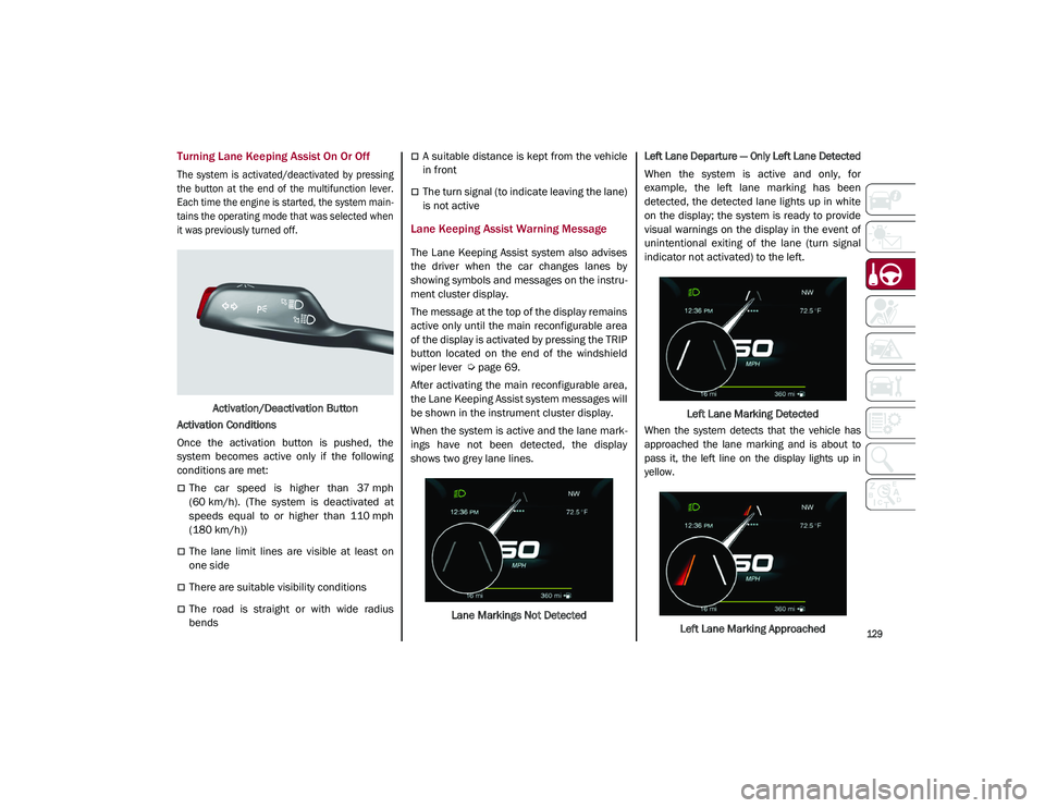
When the system is active and the lane mark -
ings have not been detected, the display
shows two grey lane lines.
Lane Markings Not Detected
Left Lane Departure — Only Left Lane Detected
When the system is active and only, for
example, the left lane marking has been
detected, the detected lane lights up in white
on the display; the system is ready to provide
visual warnings on the display in the event of
unintentional exiting of the lane (turn signal
indicator not activated) to the left.
Left Lane Marking Detected
When the system detects that the vehicle has
approached the lane marking and is about to
pass it, the left line on the display lights up in
yellow.
Left Lane Marking Approached
21_GU_OM_EN_USC_t.book Page 129
Page 138 of 280
STARTING AND OPERATING
136
Gross Vehicle Weight Rating (GVWR)
The GVWR is the total permissible weight of
your vehicle including driver, passengers,
vehicle, options and cargo. The label also
specifies maximum capacities of front and
rear axle systems (GAWR). Total load must be
limited so GVWR and front and rear GAWR are
not exceeded.
Payload
The payload of a vehicle is defined as the
allowable load weight a truck can carry,
including the weight of the driver, all passen-
gers, options and cargo.
Gross Axle Weight Rating (GAWR)
The GAWR is the maximum permissible load
on the front and rear axles. The load must be
distributed in the cargo area so that the GAWR
of each axle is not exceeded.
Each axle GAWR is determined by the compo -
nents in the system with the lowest load
carrying capacity (axle, springs, tires or
wheels). Heavier axles or suspension compo -
nents sometimes specified by purchasers for
increased durability do not necessarily
increase the vehicle's GVWR.
Tire Size
The tire size on the Vehicle Certification Label
represents the actual tire size on your vehicle.
Replacement tires must be equal to the load
capacity of this tire size.
Rim Size
This is the rim size that is appropriate for the
tire size listed.
Inflation Pressure
This is the cold tire inflation pressure for your
vehicle for all loading conditions up to full
GAWR.
Curb Weight
The curb weight of a vehicle is defined as the
total weight of the vehicle with all fluids,
including vehicle fuel, at full capacity condi -
tions, and with no occupants or cargo loaded
into the vehicle. The front and rear curb weight
values are determined by weighing your
vehicle on a commercial scale before any
occupants or cargo are added.
Loading
The actual total weight and the weight of the
front and rear of your vehicle at the ground can
best be determined by weighing it when it is
loaded and ready for operation.
The entire vehicle should first be weighed on a
commercial scale to ensure that the GVWR
has not been exceeded. The weight on the
front and rear of the vehicle should then be
determined separately to be sure that the load
is properly distributed over the front and rear
axle. Weighing the vehicle may show that the
GAWR of either the front or rear axles has
been exceeded but the total load is within the specified GVWR. If so, weight must be shifted
from front to rear or rear to front as appro
-
priate until the specified weight limitations are
met. Store the heavier items down low and be
sure that the weight is distributed equally.
Stow all loose items securely before driving.
Improper weight distributions can have an
adverse effect on the way your vehicle steers
and handles and the way the brakes operate.
TRAILER TOWING
In this section you will find safety tips and
information on limits to the type of towing you
can reasonably do with your vehicle. Before
towing a trailer, carefully review this informa -
tion to tow your load as efficiently and safely
as possible.
To maintain the New Vehicle Limited Warranty
coverage, follow the requirements and recom -
mendations in this manual concerning vehi -
cles used for trailer towing.
CAUTION!
Do not load your vehicle any heavier than
the GVWR or the maximum front and rear
GAWR. If you do, parts on your vehicle can
break, or it can change the way your vehicle
handles. This could cause you to lose
control. Also overloading can shorten the
life of your vehicle.
21_GU_OM_EN_USC_t.book Page 136
Page 154 of 280
SAFETY
152
Operating Mode
The system may be activated/deactivated via
the radio system. To access the function,
select the following items on the main menu in
sequence:
1. “Driving Assistance”
2. “Blind Spot Alert”
“Blind Spot Alert”, “Visual” Mode
When the system is enabled, the warning light
within the door mirror on the side of the
detected object illuminates.
The visual warning on the mirror will blink if the
driver activates the turn signals, indicating a
lane change.
The warning light will be constant if the driver
stays in the same lane.
“Blind Spot Alert” Function Deactivation
When the system is deactivated (“Blind Spot
Alert” mode off), the BSM or RCP systems will
not emit an audible or a visual warning.
The BSM system will store the operating mode
that was active when the engine was stopped.
Each time the engine is started, the operating
mode stored previously will be recalled and
used
Ú
page 268.
Active Blind Spot Assist (ABSA) System — If
Equipped
The ABSA system is to help avoid/limit lateral
collisions with cars coming from adjacent lanes changing the vehicle’s trajectory in order
to try to keep it in the detected lane.
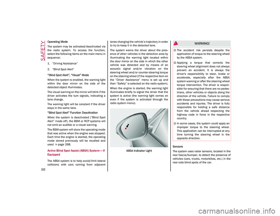
The system warns the driver about the pres
-
ence of other vehicles in the detection area by
illuminating the warning light located within
the door mirror on the side in which the other
vehicle was detected and by means of an
acoustic signal and/or vibration on the
steering wheel and/or counter-steering torque
on the steering wheel (if the respective item on
the “Driver Assistance” menu is set up and
then “Safety” is selected on the radio system).
When the engine is started, the warning light
illuminates briefly to signal the driver that the
system is active (the warning light comes on
even if the system is activated through the
radio system menu).
ABSA Indicator Light Sensors
The system uses radar sensors, located in the
rear fascia/bumper, to detect the presence of
vehicles (cars, trucks, motorbikes, etc.) in the
rear side blind spots of the car.
WARNING!
The accident risk persists despite the
application of torque to the steering wheel
by the ABSA system.
Applying a torque that corrects the
steering wheel alignment does not always
prevent an accident. It is always the
driver's responsibility to steer, brake or
accelerate, especially after the ABSA
system warning or after the steering wheel
torque intervention. The driver is respon
-
sible for ensuring that there are no pedes -
trians, other vehicles or objects along the
direction of the vehicle. Failure to comply
with these precautions may cause serious
accidents and injuries. The driver is fully
responsible for holding a safe distance
from the vehicle ahead respecting the
highway code in force in the respective
country.
In some cases, the system could apply an
improper torque to the steering wheel.
This application can be interrupted at any
time turning the steering wheel in the
opposite direction.
21_GU_OM_EN_USC_t.book Page 152
Page 156 of 280
SAFETY
154
The application of torque, as well as of the
vibration, is suppressed/inhibited if:
The torque given by the driver of the
steering wheel is high
Lateral acceleration is high
The trailer is connected to the correct
control module
At least one hand is not detected on the
steering wheel for longer than a specific
time
The turn signal is turned off
NOTE:
The steering wheel torque is not applied if the
system is unable to detect a lane and if the
direction indicator for the appropriate side has
not been switched on.
The steering wheel detects the presence of
the driver’s hands by a capacitive sensor
installed in the steering wheel and by the
applied torque measured on the steering
column.
System availability
Aggressive driving of the car, or driving on the
median lines, will prevent the correct opera -
tion of the system. In case of intervention of the stability and
braking systems (FCW, ESC, ABS) they will
prevent the system from operating.
Lane change will disable the system for a
certain period of time.
The road must also comply with some specific
characteristics, such as:
Maximum/minimum lane width.
Clearly identified and defined double yellow
lines and, for a limited period of time, a lane
with a single demarcation line.
NOTE:
In some cases, for a limited period of time, the
system may be activated by a lane with a
single median line.
In cases of good road surface conditions, the
system could correctly recognize other types
of valid lane markings (e.g. road edges, side -
walks, etc.).
Hands Presence On The Steering Wheel
Detection
The system is able to detect the presence of
the driver’s hands on the steering wheel.
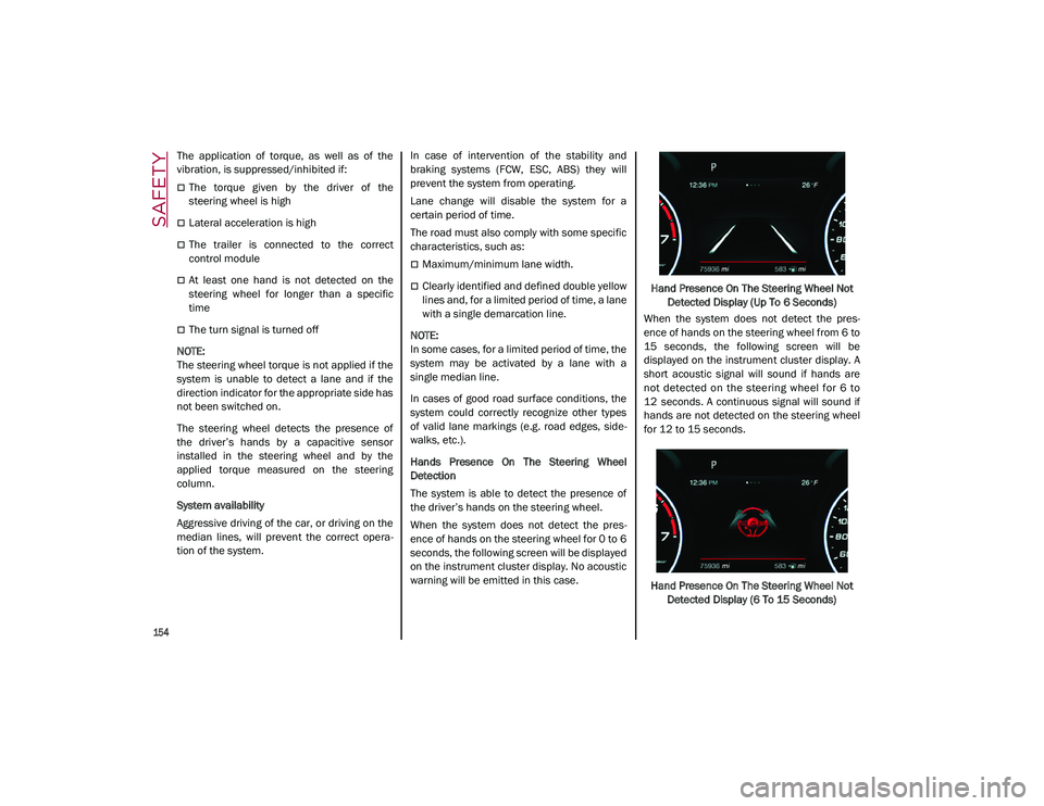
When the system does not detect the pres -
ence of hands on the steering wheel for 0 to 6
seconds, the following screen will be displayed
on the instrument cluster display. No acoustic
warning will be emitted in this case. Hand Presence On The Steering Wheel Not
Detected Display (Up To 6 Seconds)
When the system does not detect the pres -
ence of hands on the steering wheel from 6 to
15 seconds, the following screen will be
displayed on the instrument cluster display. A
short acoustic signal will sound if hands are
not detected on the steering wheel for 6 to
12 seconds. A continuous signal will sound if
hands are not detected on the steering wheel
for 12 to 15 seconds.
Hand Presence On The Steering Wheel Not Detected Display (6 To 15 Seconds)
21_GU_OM_EN_USC_t.book Page 154