2021 ALFA ROMEO STELVIO engine
[x] Cancel search: enginePage 228 of 280
SERVICING AND MAINTENANCE
226
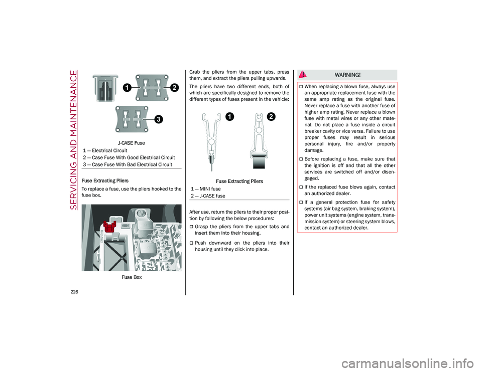
J-CASE Fuse
Fuse Extracting Pliers
To replace a fuse, use the pliers hooked to the
fuse box.
Fuse Box Grab the pliers from the upper tabs, press
them, and extract the pliers pulling upwards.
The pliers have two different ends, both of
which are specifically designed to remove the
different types of fuses present in the vehicle:
Fuse Extracting Pliers
After use, return the pliers to their proper posi -
tion by following the below procedures:
Grasp the pliers from the upper tabs and
insert them into their housing.
Push downward on the pliers into their
housing until they click into place.
1 — Electrical Circuit
2 — Case Fuse With Good Electrical Circuit
3 — Case Fuse With Bad Electrical Circuit
1 — MINI fuse
2 — J-CASE fuse
WARNING!
When replacing a blown fuse, always use
an appropriate replacement fuse with the
same amp rating as the original fuse.
Never replace a fuse with another fuse of
higher amp rating. Never replace a blown
fuse with metal wires or any other mate
-
rial. Do not place a fuse inside a circuit
breaker cavity or vice versa. Failure to use
proper fuses may result in serious
personal injury, fire and/or property
damage.
Before replacing a fuse, make sure that
the ignition is off and that all the other
services are switched off and/or disen -
gaged.
If the replaced fuse blows again, contact
an authorized dealer.
If a general protection fuse for safety
systems (air bag system, braking system),
power unit systems (engine system, trans -
mission system) or steering system blows,
contact an authorized dealer.
21_GU_OM_EN_USC_t.book Page 226
Page 233 of 280
231
*Only for basic version headlight with halogen main beam/dipped beam headlights
Replacing Exterior Bulbs
NOTE:
Only replace bulbs when the engine is off. Also
ensure that the engine is cold, to prevent the
risk of burns.
Front Light Cluster
Direction Indicators
Proceed with the directions below to change
bulbs:
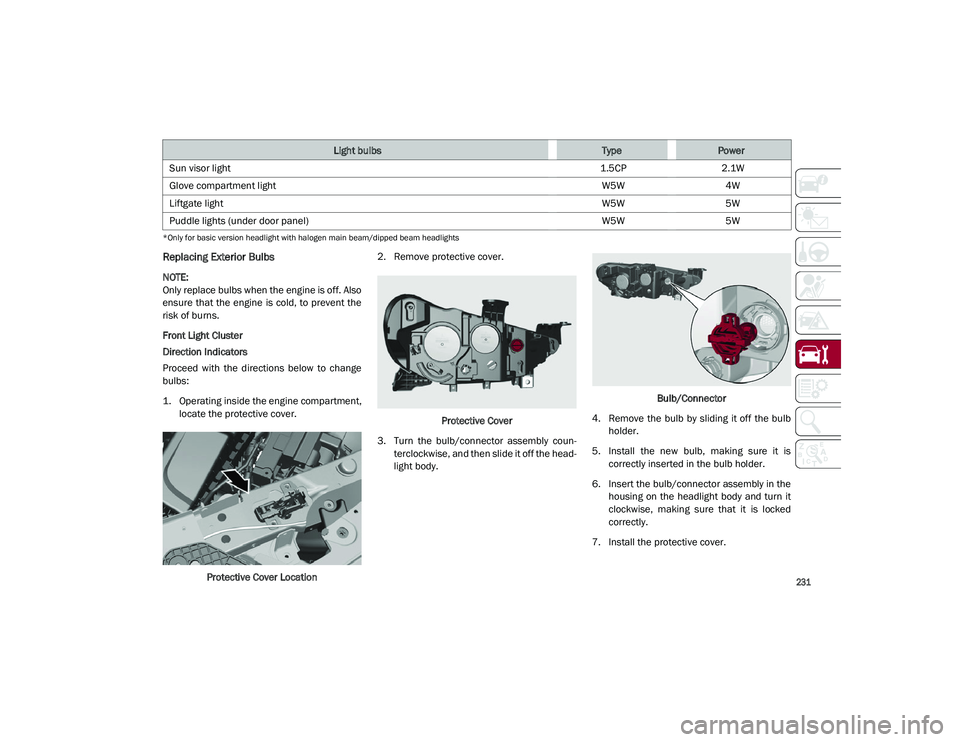
1. Operating inside the engine compartment,locate the protective cover.
Protective Cover Location 2. Remove protective cover.
Protective Cover
3. Turn the bulb/connector assembly coun -
terclockwise, and then slide it off the head -
light body. Bulb/Connector
4. Remove the bulb by sliding it off the bulb holder.
5. Install the new bulb, making sure it is correctly inserted in the bulb holder.
6. Insert the bulb/connector assembly in the housing on the headlight body and turn it
clockwise, making sure that it is locked
correctly.
7. Install the protective cover.
Sun visor light
1.5CP2.1W
Glove compartment light W5W4W
Liftgate light W5W5W
Puddle lights (under door panel) W5W5W
Light bulbsTypePower
21_GU_OM_EN_USC_t.book Page 231
Page 243 of 280
241
Recommended Cold Tire Inflation Pressures
For vehicle speeds below 100 mph (160 km/h),
recommended cold tire inflation pressures are
listed on the Tire And Loading Information
Placard located on driver’s side B-pillar or the
rear edge of the driver's side door.
When driving at speeds 100 mph (160 km/h)
and above, increased tire pressures and
reduced vehicle loading are required for
high-speed vehicle operation.For driving speeds above 100 mph (160 km/h)
recommended cold tire inflation pressures are
listed below under "High Speed Tire Inflation
Pressure". Vehicle loading condition must not
exceed 688 lbs. (312 kg) (driver + three
passengers + 88 lbs. (40kg) luggage).
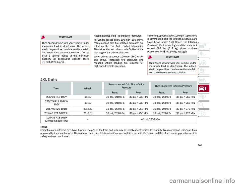
2.0L Engine
NOTE:
Using tires of a different size, type, brand or design on the front and rear may adversely affect vehicle drive-ability. We recommend using only tires
approved by the manufacturer. The manufacturer cannot determine if unapproved tires are suitable for use and therefore cannot guarantee vehicle
safety in those conditions.
WARNING!
High speed driving with your vehicle under
maximum load is dangerous. The added
strain on your tires could cause them to fail.
You could have a serious collision. Do not
drive a vehicle loaded to the maximum
capacity at continuous speeds above
75 mph (120 km/h).
WARNING!
High speed driving with your vehicle under
maximum load is dangerous. The added
strain on your tires could cause them to fail.
You could have a serious collision.
TiresWheel
Recommended Cold Tire Inflation PressureHigh Speed Tire Inflation Pressure
FrontRearFrontRear
235/60 R18 103V 18x8J30 psi / 210 kPa 33 psi / 230 kPa 33 psi / 230 kPa 38 psi / 260 kPa
235/55 R19 101V & 105V 19x8J
30 psi / 210 kPa 33 psi / 230 kPa 33 psi / 230 kPa 38 psi / 260 kPa
255/45 R20 101H 20x8.5J33 psi / 230 kPa 36 psi / 250 kPa 35 psi / 240 kPa 39 psi / 270 kPa
255/40 R21 102W XL 21x8.5J33 psi / 230 kPa 36 psi / 250 kPa 33 psi / 230 kPa 39 psi / 270 kPa
195/75 R18 106P
(Compact Spare Tire) –
43 psi / 300 kPa
21_GU_OM_EN_USC_t.book Page 241
Page 244 of 280
SERVICING AND MAINTENANCE
242
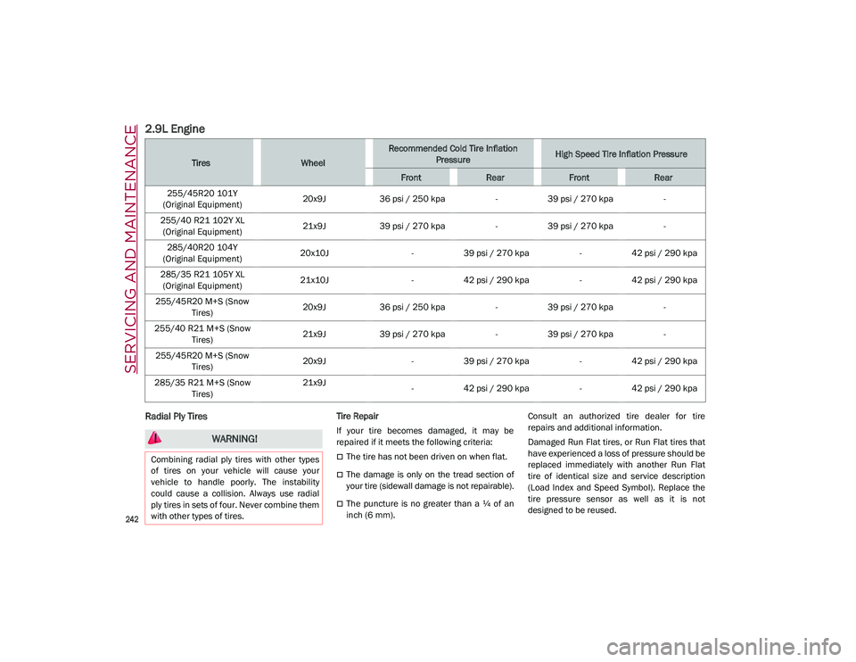
2.9L Engine
Radial Ply Tires Tire Repair
If your tire becomes damaged, it may be
repaired if it meets the following criteria:
The tire has not been driven on when flat.
The damage is only on the tread section of
your tire (sidewall damage is not repairable).
The puncture is no greater than a ¼ of an
inch (6 mm).Consult an authorized tire dealer for tire
repairs and additional information.
Damaged Run Flat tires, or Run Flat tires that
have experienced a loss of pressure should be
replaced immediately with another Run Flat
tire of identical size and service description
(Load Index and Speed Symbol). Replace the
tire pressure sensor as well as it is not
designed to be reused.
TiresWheel
Recommended Cold Tire Inflation
PressureHigh Speed Tire Inflation Pressure
FrontRearFrontRear
255/45R20 101Y
(Original Equipment) 20x9J
36 psi / 250 kpa -39 psi / 270 kpa -
255/40 R21 102Y XL (Original Equipment) 21x9J
39 psi / 270 kpa -39 psi / 270 kpa -
285/40R20 104Y
(Original Equipment) 20x10J
-39 psi / 270 kpa -42 psi / 290 kpa
285/35 R21 105Y XL (Original Equipment) 21x10J
-42 psi / 290 kpa -42 psi / 290 kpa
255/45R20 M+S (Snow Tires) 20x9J
36 psi / 250 kpa -39 psi / 270 kpa -
255/40 R21 M+S (Snow Tires) 21x9J
39 psi / 270 kpa -39 psi / 270 kpa -
255/45R20 M+S (Snow Tires) 20x9J
-39 psi / 270 kpa -42 psi / 290 kpa
285/35 R21 M+S (Snow Tires) 21x9J
-42 psi / 290 kpa -42 psi / 290 kpa
WARNING!
Combining radial ply tires with other types
of tires on your vehicle will cause your
vehicle to handle poorly. The instability
could cause a collision. Always use radial
ply tires in sets of four. Never combine them
with other types of tires.
21_GU_OM_EN_USC_t.book Page 242
Page 249 of 280

247
(Continued)
tires only in sets of four; failure to do so may
adversely affect the safety and handling of
your vehicle.
Snow tires generally have lower speed ratings
than what was originally equipped with your
vehicle and should not be operated at
sustained speeds over 75 mph (120 km/h).
For speeds above 75 mph (120 km/h) refer to
original equipment or an authorized tire dealer
for recommended safe operating speeds,
loading and cold tire inflation pressures.
While studded tires improve performance on
ice, skid and traction capability on wet or dry
surfaces may be poorer than that of
non-studded tires. Some states prohibit
studded tires; therefore, local laws should be
checked before using these tire types.
Tire Chains and Traction Devices
It is possible to fit 13 mm chains on all the
tires except for R20.
Use of traction devices require sufficient
tire-to-body clearance. Follow these recom-
mendations to guard against damage.
NOTE:
Traction device must be of proper size for
the tire, as recommended by the traction
device manufacturer.
Use on rear tires only.
Check the tension of the snow chains after
the first few meters have been driven.
Using snow chains with tires with non-orig -
inal dimensions may damage the vehicle.
Using different tires sizes or types (M+S,
snow, etc.) between the front and rear axles
may adversely affect vehicle driveability,
with the risk of losing control of the vehicle
and resulting accidents.
Tire Rotation Recommendations
Tires on the front and rear axles of vehicles
operate at different loads and perform
different steering, driving, and braking func -
tions. For these reasons, they wear at unequal
rates. These effects can be reduced by timely
rotation of tires. Rotation will increase tread
life, maintain traction levels and contribute to
a smooth, quiet ride.
To resolve this problem, tires should be
rotated at each service interval (approximately
every 10,000 miles [16,000 km]). More
frequent rotation is permissible if desired. The
reasons for any rapid or unusual wear should
be corrected prior to rotation being performed.
Tire Rotations Not Recommended — If
Equipped
Due to different size tires and wheels on front
and rear axles tire rotation is not possible for:
2.0T GME Engine equipped with a different
front and rear tire size.
CAUTION!
To avoid damage to your vehicle or tires,
observe the following precautions:
Because of restricted traction device
clearance between tires and other
suspension components, it is important
that only traction devices in good condi -
tion are used. Broken devices can cause
serious damage. Stop the vehicle immedi -
ately if noise occurs that could indicate
device breakage. Remove the damaged
parts of the device before further use.
Install device as tightly as possible and
then retighten after driving about ½ mile
(0.8 km).
Do not exceed 30 mph (48 km/h).
Drive cautiously and avoid severe turns
and large bumps, especially with a loaded
vehicle.
Do not drive for a prolonged period on dry
pavement.
Observe the traction device manufac -
turer’s instructions on the method of
installation, operating speed, and condi -
tions for use. Always use the suggested
operating speed of the device manufac -
turer’s if it is less than 30 mph (48 km/h).
Do not use traction devices on a compact
spare tire.
CAUTION! (Continued)
21_GU_OM_EN_USC_t.book Page 247
Page 251 of 280
249
test wheel. Sustained high temperature
can cause the material of the tire to
degenerate and reduce tire life, and
excessive temperature can lead to
sudden tire failure. The grade C corre-
sponds to a level of performance, which
all passenger vehicle tires must meet
under the Federal Motor Vehicle Safety
Standard No. 109. Grades B and A
represent higher levels of performance
on the laboratory test wheel, than the
minimum required by law.
STORING THE VEHICLE
If the vehicle is left inactive for longer than a
month, the following precautions should be
observed:
Park the vehicle in an area that is covered
and dry, and well-ventilated if possible.
Slightly open the windows.
Check that the Electric Park Brake (EPB) is
not activated.
Carry out the “Liftgate Emergency Opening”
procedure
Ú
page 62.
Disconnect the negative battery terminal
and check the battery charge. Repeat this
check once every three months during
storage.
If the battery is not disconnected from the
electrical system, check its state of charge
every 30 days.
Clean and protect the painted parts using
protective wax.
Clean and protect the shiny metal parts using
special compounds available commercially.
Sprinkle talcum powder on the windshield
wiper rubber blades, and lift them off the
glass.
Cover the vehicle with a fabric or perforated
plastic sheet, paying particular care not to
damage the painted surface by dragging
any dust that may have accumulated on it.
Do not use compact plastic sheets, as they
do not allow humidity to evaporate from the
surface of the vehicle.
Inflate tires to +7.25 psi (+0.5 bar) above
the standard prescribed pressure and
check it periodically.
Do not drain the engine cooling system.
Any time the vehicle is left inactive for two
weeks or more, operate the air conditioning
system with engine idling for at least five minutes, setting external air and with fan
set to maximum speed. This operation will
ensure appropriate lubrication for the
system, thus minimizing the possibility of
damage to the compressor when the
system is operated again.
NOTE:
After cycling the ignition to STOP and having
closed the driver side door, wait at least one
minute before disconnecting the electrical
supply from the battery. When reconnecting
the electrical supply to the battery, make sure
that the ignition is in the STOP position and the
driver’s side door is closed.
BODYWORK
Protection Against Atmospheric Agents
The vehicle is equipped with the best available
technological solutions to protect the body -
work against corrosion.
These include:
Painting products and systems which give
the vehicle resistance to corrosion and
abrasion.
Use of galvanized (or pre-treated) steel
sheets, with high resistance to corrosion.
Spraying of plastic parts, with a protective
function in the more exposed points: under
door, inner wing, edges, etc.
WARNING!
The temperature grade for this tire is
established for a tire that is properly inflated
and not overloaded. Excessive speed,
underinflation, or excessive loading, either
separately or in combination, can cause
heat buildup and possible tire failure.
21_GU_OM_EN_USC_t.book Page 249
Page 253 of 280
251
NOTE:
Never use aromatic substances (e.g. gaso-
line) or ketones (e.g. acetone) for cleaning
the plastic lenses of the headlights.
When cleaning with a pressure washer,
keep the pressure washer at least eight
inches (20 cm) away from the headlights.
Engine Compartment
At the end of every Winter, wash the engine
compartment thoroughly, taking care not to
aim the jet of water directly at the electronic
control units or at the windshield wiper
motors. Have this operation performed at a
specialized workshop
Ú
page 218.
NOTE:
The washing should take place with the engine
cold and the ignition device in the STOP posi -
tion. After the washing operation, make sure
that the various protections (e.g. rubber caps
and guards) have not been removed or
damaged.
INTERIORS
Periodically check the cleanliness of the inte -
rior, beneath the mats, which could cause
oxidation of the sheet metal.
Seats And Fabric Parts
Remove dust with a soft brush or a vacuum
cleaner. It is advised to use a moist brush on
velvet upholstery. Rub the seats with a sponge
moistened with a solution of water and neutral
detergent. Cleaning heat press images on seats — if
equipped:
Due to the color, opacity and wear-resistant
protection with which the heat press images
on some seats are made, they may be subject
to temporary scratching if they are touched by
finger nails, keys, or other hard objects. In
such cases, the visible signs do not impair the
profiled images, and can easily be removed by
wiping the affected area with a microfiber
cloth moistened with water (not dry) to restore
the seat to its original condition. The micro
-
fiber cloth must not have been previously
soaked in other substances or detergents.
Leather Seats
Remove the dry dirt with a chamois or slightly
damp cloth, without exerting too much pres -
sure.
Remove any liquid or grease stains using an
absorbent dry cloth, without rubbing. Then
clean with a soft cloth or buckskin cloth damp -
ened with water and mild soap. If the stain
persists, use specific products and observe
the instructions carefully.
NOTE:
Never use alcohol. Make sure that the
cleaning products used contain no alcohol or
alcohol derivatives, even in small quantities.
Plastic And Coated Parts
Clean interior plastic parts with a damp cloth (if
possible made from microfiber), and a solution
of water and neutral, non-abrasive detergent. To clean oily or persistent stains, use specific
products free from solvents and designed to
maintain the original appearance and color of
the components.
Remove any dust using a microfiber cloth, if
necessary moistened with water. The use of
paper tissues is not recommended as these
may leave residues.
Alcantara Parts — If Equipped
Alcantara parts maintenance procedure:
Treat the surface with a microfiber cloth
moistened with mild marseille soap and
water, taking care to apply a uniform light
pressure over the entire area (do not rub
vigorously).
Rinse and wring out the microfiber cloth,
and pass it over the entire area again.
Let it dry, and then brush gently with a soft
brush.
Genuine Leather Parts
Use only water and mild soap to clean these
parts. Never use alcohol or alcohol-based
products.
CAUTION!
Precautions have been taken to safeguard
all parts and connections however, the
pressures generated by these machines is
such that complete protection against
water ingress cannot be guaranteed.
21_GU_OM_EN_USC_t.book Page 251
Page 256 of 280

TECHNICAL SPECIFICATIONS
254
ENGINE
2.0L Engine
Cycle Four
Number and position of cylinders 4 inline
Piston bore and stroke (mm) 84 / 90
Total displacement (cm³) 1,995
Compression ratio 10:1
Maximum power (SAE) (HP) 280
Maximum power (kW) 209
Corresponding engine speed (RPM) 5,200
Maximum torque (SAE) (ft-lb) 295
Maximum torque (Nm) 400
Corresponding engine speed (RPM) 2,250 - 4,000
Fuel 87 Octane Minimum (R+M)/2 Method, 91 Recommended, ethanol
percentage is 0–15%.
2.9L Engine
Cycle Four
Number and position of cylinders 6 / V
Piston bore and stroke (mm) 86.5 × 82
Total displacement (cm³) 2,891
Compression ratio 9.3:1
Maximum power (SAE) (HP) 505
Maximum power (kW) 375
Corresponding engine speed (RPM) 6,500
Maximum torque (SAE) (ft-lb) 443
21_GU_OM_EN_USC_t.book Page 254