2021 ALFA ROMEO STELVIO torque
[x] Cancel search: torquePage 13 of 280
11
LANE KEEPING ASSIST (LKA)
SYSTEM —IF EQUIPPED......................... 128
Turning Lane Keeping Assist On Or
Off ......................................................... 129 Lane Keeping Assist Warning
Message ...............................................129
REAR BACK UP CAMERA / DYNAMIC
GRIDLINES ............................................. 132 REFUELING THE VEHICLE ..................... 133
Refueling The Vehicle ..........................133
Refueling Capacity ............................... 133
Refueling Procedure ...........................133
VEHICLE LOADING ................................. 135
Certification Label................................ 135
TRAILER TOWING................................... 136
Common Towing Definitions ...............137
Trailer Hitch Classification .................. 137
Trailer Towing Weights (Maximum
Trailer Weight Ratings) .....................138 Trailer And Tongue Weight ................. 138
Towing Requirements..........................139
Towing Tips ..........................................141
Installing The Receiver ........................ 141
Connecting The Electrical System ......141
Removing The Receiver ....................... 142
SUGGESTIONS FOR DRIVING................ 142
Saving Fuel ...........................................142
Driving Style .........................................142
Conditions Of Use ................................ 142
Performance — Quadrifoglio ...............143
SAFETY
ACTIVE SAFETY SYSTEMS...................... 145
Anti-Lock Brake System (ABS) ........... 145
Active Torque Vectoring (ATV)
System — If Equipped .......................... 145 Dynamic Steering Torque (DST)
System ................................................. 146 Drive Train Control (DTC) System ....... 146
Electronic Stability Control (ESC)
System ................................................. 146 Hill Descent Control (HDC) System —
If Equipped ........................................... 147 Hill Start Assist (HSA) System ............. 148
Panic Brake Assist (PBA) System ....... 149
Traction Control System (TCS) ............ 149
AUXILIARY DRIVING SYSTEMS .............. 149
Blind Spot Monitoring (BSM) System —
If Equipped ......................................... 150 Active Blind Spot Assist (ABSA)
System — If Equipped ......................... 152 Driver Attention Assist (DAA)
System — If Equipped .......................... 155 Forward Collision Warning Plus (FCW+)
System — If Equipped ......................... 156 Tire Pressure Monitoring System
(TPMS) .................................................. 161
OCCUPANT RESTRAINT SYSTEMS ........ 163
Occupant Restraint Systems
Features .............................................. 163 Important Safety Precautions ............ 163
Seat Belt Systems .............................. 164
Supplemental Restraint Systems
(SRS) .................................................... 169 Child Restraints ................................. 178
SAFETY TIPS .......................................... 188
Transporting Passengers .................... 188
Transporting Pets ............................. 189
Safety Checks You Should Make
Inside The Vehicle .............................. 189 Periodic Safety Checks You Should
Make Outside The Vehicle .................. 190 Exhaust Gas ..................................... 190
Carbon Monoxide Warnings ............. 191
IN CASE OF EMERGENCY
HAZARD WARNING FLASHERS ............. 192
SOS — EMERGENCY CALL ..................... 192
JACKING AND TIRE CHANGING............. 195
General Instructions ........................... 195
Jack Information And Usage
Precautions ......................................... 195 Changing Procedure ........................... 196
TIRE SERVICE KIT — IF EQUIPPED ........ 198
Description .......................................... 198
Inflation Procedure ............................. 199
Checking And Restoring Tire
Pressure............................................... 201
21_GU_OM_EN_USC_t.book Page 11
Page 17 of 280
15
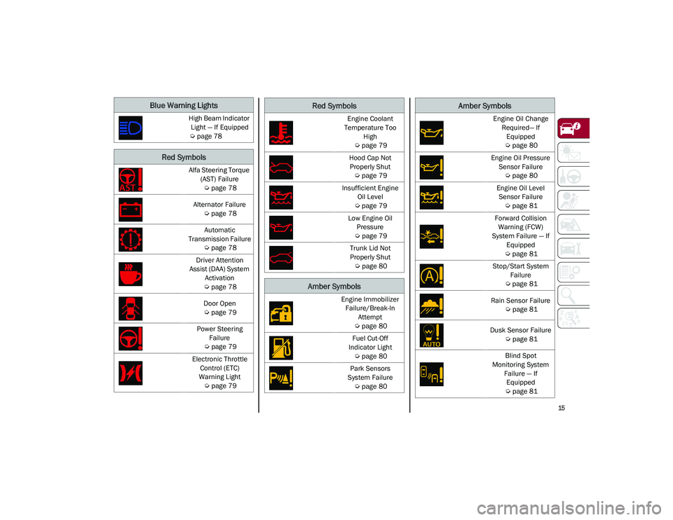
Blue Warning Lights
High Beam Indicator Light — If Equipped
Ú
page 78
Red Symbols
Alfa Steering Torque
(AST) Failure
Ú
page 78
Alternator Failure
Ú
page 78
Automatic
Transmission Failure
Ú
page 78
Driver Attention
Assist (DAA) System Activation
Ú
page 78
Door Open
Ú
page 79
Power Steering Failure
Ú
page 79
Electronic Throttle Control (ETC)
Warning Light
Ú
page 79
Engine Coolant
Temperature Too High
Ú
page 79
Hood Cap Not Properly Shut
Ú
page 79
Insufficient Engine Oil Level
Ú
page 79
Low Engine Oil Pressure
Ú
page 79
Trunk Lid Not
Properly Shut
Ú
page 80
Amber Symbols
Engine Immobilizer
Failure/Break-In Attempt
Ú
page 80
Fuel Cut-Off
Indicator Light
Ú
page 80
Park Sensors
System Failure
Ú
page 80
Red Symbols
Engine Oil Change
Required— If Equipped
Ú
page 80
Engine Oil Pressure Sensor Failure
Ú
page 80
Engine Oil Level Sensor Failure
Ú
page 81
Forward Collision Warning (FCW)
System Failure — If Equipped
Ú
page 81
Stop/Start System Failure
Ú
page 81
Rain Sensor Failure
Ú
page 81
Dusk Sensor Failure
Ú
page 81
Blind Spot
Monitoring System Failure — If Equipped
Ú
page 81
Amber Symbols
21_GU_OM_EN_USC_t.book Page 15
Page 74 of 280
GETTING TO KNOW YOUR INSTRUMENT PANEL
72
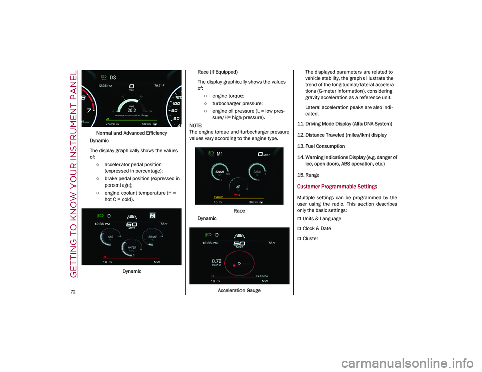
Normal and Advanced Efficiency
Dynamic
The display graphically shows the values
of: ○ accelerator pedal position (expressed in percentage);
○ brake pedal position (expressed in percentage);
○ engine coolant temperature (H = hot C = cold).
Dynamic Race (If Equipped)
The display graphically shows the values
of:
○ engine torque;
○ turbocharger pressure;
○ engine oil pressure (L = low pres -
sure/H= high pressure).
NOTE:
The engine torque and turbocharger pressure
values vary according to the engine type.
Race
Dynamic
Acceleration Gauge The displayed parameters are related to
vehicle stability, the graphs illustrate the
trend of the longitudinal/lateral accelera
-
tions (G-meter information), considering
gravity acceleration as a reference unit.
Lateral acceleration peaks are also indi -
cated.
11. Driving Mode Display (Alfa DNA System)
12. Distance Traveled (miles/km) display
13. Fuel Consumption
14. Warning Indications Display (e.g. danger of ice, open doors, ABS operation, etc.)
15. Range
Customer Programmable Settings
Multiple settings can be programmed by the
user using the radio. This section describes
only the basic settings:
Units & Language
Clock & Date
Cluster
21_GU_OM_EN_USC_t.book Page 72
Page 80 of 280
GETTING TO KNOW YOUR INSTRUMENT PANEL
78
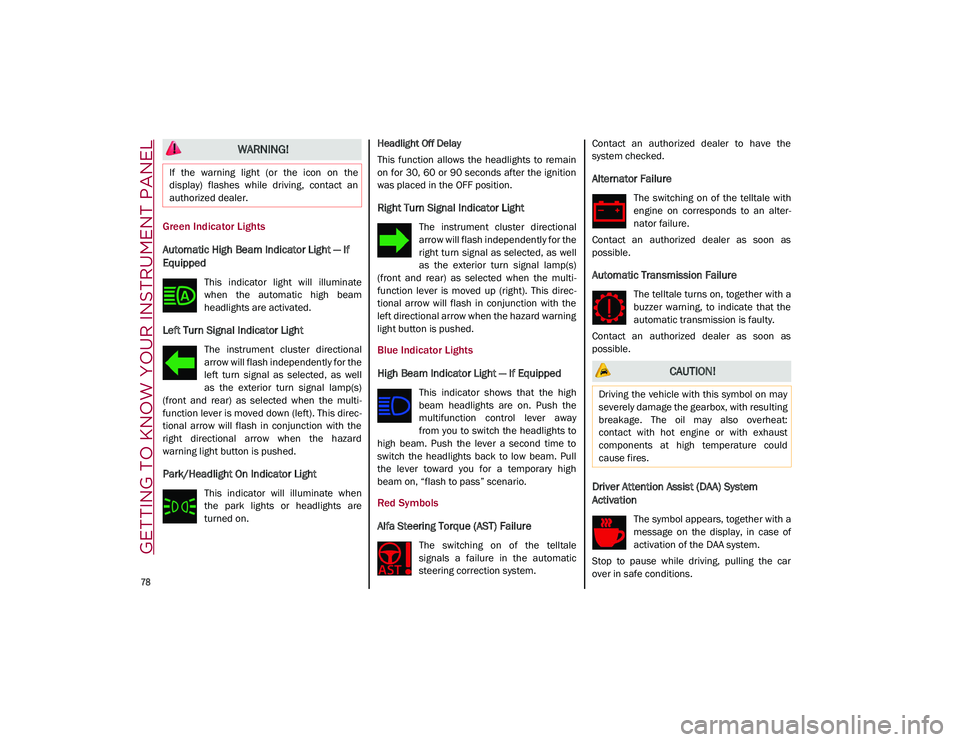
Green Indicator Lights
Automatic High Beam Indicator Light — If
Equipped
This indicator light will illuminate
when the automatic high beam
headlights are activated.
Left Turn Signal Indicator Light
The instrument cluster directional
arrow will flash independently for the
left turn signal as selected, as well
as the exterior turn signal lamp(s)
(front and rear) as selected when the multi -
function lever is moved down (left). This direc -
tional arrow will flash in conjunction with the
right directional arrow when the hazard
warning light button is pushed.
Park/Headlight On Indicator Light
This indicator will illuminate when
the park lights or headlights are
turned on. Headlight Off Delay
This function allows the headlights to remain
on for 30, 60 or 90 seconds after the ignition
was placed in the OFF position.
Right Turn Signal Indicator Light
The instrument cluster directional
arrow will flash independently for the
right turn signal as selected, as well
as the exterior turn signal lamp(s)
(front and rear) as selected when the multi -
function lever is moved up (right). This direc -
tional arrow will flash in conjunction with the
left directional arrow when the hazard warning
light button is pushed.
Blue Indicator Lights
High Beam Indicator Light — If Equipped
This indicator shows that the high
beam headlights are on. Push the
multifunction control lever away
from you to switch the headlights to
high beam. Push the lever a second time to
switch the headlights back to low beam. Pull
the lever toward you for a temporary high
beam on, “flash to pass” scenario.
Red Symbols
Alfa Steering Torque (AST) Failure
The switching on of the telltale
signals a failure in the automatic
steering correction system. Contact an authorized dealer to have the
system checked.
Alternator Failure
The switching on of the telltale with
engine on corresponds to an alter
-
nator failure.
Contact an authorized dealer as soon as
possible.
Automatic Transmission Failure
The telltale turns on, together with a
buzzer warning, to indicate that the
automatic transmission is faulty.
Contact an authorized dealer as soon as
possible.
Driver Attention Assist (DAA) System
Activation
The symbol appears, together with a
message on the display, in case of
activation of the DAA system.
Stop to pause while driving, pulling the car
over in safe conditions.
WARNING!
If the warning light (or the icon on the
display) flashes while driving, contact an
authorized dealer.
CAUTION!
Driving the vehicle with this symbol on may
severely damage the gearbox, with resulting
breakage. The oil may also overheat:
contact with hot engine or with exhaust
components at high temperature could
cause fires.
21_GU_OM_EN_USC_t.book Page 78
Page 100 of 280
STARTING AND OPERATING
98
ALFA DNA SELECTOR
Alfa DNA System
This vehicle is equipped with an Alfa DNA
system selector (located on the center
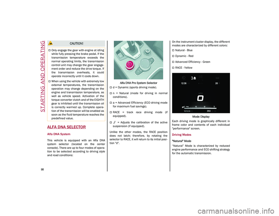
console). There are up to four modes of opera-
tion to be selected according to driving style
and road conditions: Alfa DNA Pro System Selector
d = Dynamic (sports driving mode).
n = Natural (mode for driving in normal
conditions).
a = Advanced Efficiency (ECO driving mode
for maximum fuel savings).
RACE = track race driving mode (if
equipped).
= Adjusts the calibration of the active
suspension (if equipped).
Unlike the other modes, the RACE position
does not latch; therefore, by rotating the
selector to RACE, it will return to its initial posi -
tion "d". On the instrument cluster display, the different
modes are characterized by different colors:
Natural - Blue
Dynamic - Red
Advanced Efficiency - Green
RACE - Yellow
Mode Display
Each driving mode is graphically different in
frame color and contents of each individual
"performance" screen.
Driving Modes
"Natural" Mode
“Natural” Mode is characterized by reduced
engine performance and ECO shifting strategy
for the automatic transmission.
CAUTION!
Only engage the gear with engine at idling
while fully pressing the brake pedal. If the
transmission temperature exceeds the
normal operating limits, the transmission
control unit may change the gear engage -
ment order and reduce the drive torque. If
the transmission overheats, it could
operate incorrectly until it cools down.
When using the vehicle with extremely low
external temperatures, the transmission
operation may change depending on the
engine and transmission temperature, as
well as vehicle speed. Activation of the
torque converter clutch and of the EIGHTH
gear is inhibited until the transmission oil
is correctly warmed up. Complete opera -
tion of the transmission will be enabled as
soon as the fluid temperature reaches the
predefined value.
21_GU_OM_EN_USC_t.book Page 98
Page 130 of 280
STARTING AND OPERATING
128
The system operates in the same way, but
mirrored, in the event of exiting the right lane
when only the right lane marking has been
detected.
Left Lane Departure — Both Lanes Detected
When the system is active, both lane lines on
the display illuminate in white to indicate that
both of the lane markings have been detected.
When lane markings are detected, the system
is ready to provide indications in case the
driver unintentionally leaves the lane (turn
signal not activated).
As the Lane Departure Warning system
detects the lane markings while the vehicle is
in motion, it will adjust the display accordingly
(from white to yellow and yellow to white, and
increase their thickness).
If a lane line is crossed, the driver is alerted by
an audible signal as well as the visual indica-
tion in the instrument cluster. The signal is
emitted through the speakers on the side of
the lane limit which is being crossed (e.g. if the
vehicle is exceeding the left line of the lane,
the audible signal will come from the speakers
on the left of the vehicle).
Limited Operation Warning
If a message appears on the display, a condi -
tion limiting the Lane Departure Warning
system operation may have occurred. This
could be an obstruction of the camera view, or
a fault in the system.
If an obstruction is detected, clean the area of
the windshield by the interior rearview mirror. Although the vehicle can still be driven in
normal conditions, the system may not func
-
tion properly.
When the conditions limiting the system are
corrected, it will go back to normal operation.
Should a fault persist, contact an authorized
dealer.
System Failure Warning
If the system turns off and appears on the
display, it means that there is a system fault.
In this case, it is still possible to drive the
vehicle, but you are advised to contact an
authorized dealer as soon as possible.
Changing Lane Departure Warning Status
The system's sensitivity can be set through the
radio system. Sensitivity “High” or “Low” can
be selected.
To access the function, from the main menu
select the following in order:
1. “Settings”
2. “Driver Assistance”
3. “Lane Departure Warning”
4. “Sensitivity”
LANE KEEPING ASSIST (LKA)
SYSTEM —IF EQUIPPED
The Lane Keeping Assist (LKA) system uses a
camera located on the windshield to detect
the lane markings and calculate the position of the vehicle within such markings, in order to
make sure that the vehicle remains inside the
lane. This is an active system that will apply
torque to the steering wheel if it senses that
the vehicle is drifting out of the lane.
When one or both lane markings are detected
and the vehicle passes over one without a turn
signal being applied, the system will apply
torque to the steering wheel and a visual
signal will be displayed in the instrument
cluster display. An audible signal may also
sound.
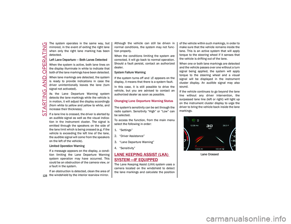
If the vehicle continues to go beyond the lane
line without any driver intervention, the
surpassed lane line (left or right) will light up
on the instrument cluster display to urge the
driver to bring the vehicle back inside the lane
markings.
Lane Crossed
21_GU_OM_EN_USC_t.book Page 128
Page 144 of 280
STARTING AND OPERATING
142
Removing The Receiver
When the receiver is no longer needed, discon-
nect the electrical connections and remove it
from its position using the directions below:
1. Remove the safety split ring from the locking pin.
2. Pull the locking pin out of the trailer hitch.
3. Remove the receiver from the trailer hitch.
SUGGESTIONS FOR DRIVING
Saving Fuel
Below are some suggestions which may help
you save fuel and lower the amount of harmful
emissions released into the atmosphere.
Vehicle Maintenance
Checks and operations should be carried out
in accordance with the Maintenance Plan
Ú
page 208.
Tires
Check the tire pressures at least once every
four weeks: if the pressure is too low,
consumption levels increase as resistance to
rolling is higher.
NOTE:
Tire pressure that is too high can cause
premature tire wear, reduced control, etc. Unnecessary Loads
Do not travel with an overloaded liftgate. The
weight of the vehicle and its arrangement
greatly affect fuel consumption and stability.
Electric Devices
Use electrical systems only for the amount of
time needed. The rear window defroster, addi
-
tional headlights, windshield wipers and
heater blower fan require a considerable
amount of energy; increasing the current
uptake increases fuel consumption (by up to
+25% when city driving).
Climate Control System
Using the climate control system will increase
consumption: use standard ventilation when
the temperature outside permits.
Devices For Aerodynamic Control
The use of non-certified devices for aerody -
namic control may adversely affect air drag
and consumption levels.
Driving Style
Starting
Do not warm up the engine at low or high revs
when the vehicle is stationary; this causes the
engine to warm up more slowly, thereby
increasing fuel consumption and emissions. It
is therefore advisable to drive off immediately,
slowly, avoiding high speeds: by doing this the
engine will warm up more quickly. Unnecessary Actions
Avoid revving up when starting at traffic lights
or before stopping the engine. This action is
unnecessary and causes increased fuel
consumption and pollution.
Gear Selection
Use a high gear when traffic and road condi
-
tions allow it. Using a low gear for faster accel -
eration will increase fuel consumption.
Improper use of a high gear increases
consumption, emissions and engine wear.
Max. Speed
Fuel consumption considerably increases as
speed increases. Maintain a constant speed,
avoiding unnecessary braking and accelera -
tion, which cost in terms of both fuel consump -
tion and emissions.
Acceleration
Accelerating violently severely affects
consumption and emissions: acceleration
should be gradual and should not exceed the
maximum torque.Conditions Of Use
Cold Starting
Short trips and frequent cold starts will not
allow the engine to reach optimum operating
temperature. This results in a significant
increase in consumption levels (from +15 to
+30% in city driving) and emissions.
21_GU_OM_EN_USC_t.book Page 142
Page 145 of 280
143
Traffic And Road Conditions
High fuel consumption is caused by heavy
traffic, for instance when traveling in traffic
with frequent use of low gears or in cities with
many traffic lights. Winding mountain roads
and rough road surfaces also adversely affect
consumption.
Stops In Traffic
During prolonged stops (e.g. railway cross-
ings), turn off the engine.
Performance — Quadrifoglio
This vehicle is equipped with an engine
capable of delivering exceptionally fast accel -
eration and speed:
Peak power: 505 HP at 6,500 RPM.
Peak torque: 443 ft-lbs at 2,500–5,000 RPM.
Top speed: 176 mph (283 km/h).
Acceleration from 0 to 60 mph (0 to 100 km/h):
3.6 seconds.
For safe driving, it is essential, particularly
during the first days of use, to get to know the
car by driving carefully and gradually discov -
ering its performance.
Brakes
The car braking system may be available with
four carbon-ceramic material brake discs, one
on each wheel. In order to guarantee the maximum braking
capacity for the first use, Alfa Romeo performs
a "run-in" procedure for discs and pads directly
at the factory.
The use of carbon-ceramic material brake
discs guarantees braking features (better
deceleration/pedal load ratio, braking
distances, fading resistance) proportional to
the dynamic features of the car in addition to
considerably decreasing the unsprung compo
-
nent weight.
The materials used and the structural features
of the system could generate unusual noises
which have absolutely no adverse effect on
correct operation and reliability of the braking
system.
Greater pressure may need to be applied to
the brake pedal the first time to keep the same
braking capacities in presence of condensa -
tion or salt on the braking surfaces, for
example after washing or if the car is not used
for a long time.
NOTE:
Given the high technological level of this
system, any servicing on it must be performed
by an authorized dealer which exclusively has
the skills needed for the repair and mainte -
nance operations. In case of intensive, high-performance use of
the car, have the efficiency of the
carbon-ceramic material braking system
inspected as shown on the Maintenance Plan
at an authorized dealer.
Driving On Race Tracks
Before driving on a track using a racing style, it
is necessary to:
Attend a race track driving course.
Check the liquid levels in the engine
compartment
Ú
page 208.
Have the car inspected at an authorized
dealer.
Remember that the car was not designed to be
driven exclusively on the race track and that
this use increases stress and component
wear.
NOTE:
Quadrifoglio front brakes are equipped with
Non-Asbestos Organic (NAO) type pads. These
pads are NOT suitable for high thermal loads
(for example track use). If you want to use
vehicle on a track it is recommended to use
the optional CCM Brakes (Carbon Ceramic
Brake disc).
21_GU_OM_EN_USC_t.book Page 143