Page 49 of 108

Instrument and control functions
4-28
1
2
345
6
7
8
9
10
11
12
3. Turn the accessory off.
4. Insert the accessory plug into the
auxiliary DC jack.
5. Turn the main switch on, and start the engine. (See page 6-1.)
6. Turn the accessory on.
WARNING
EWA14361
To prevent electrical shock or
short-circuiting, make sure that the
cap is installed when the auxiliaryDC jack is not being used.
EAU15306
SidestandThe sidestand is located on the left side
of the frame. Raise the sidestand or
lower it with your foot while holding the
vehicle upright.TIPThe built-in sidestand switch is part of
the ignition circuit cut-off system, which
cuts the ignition in certain situations.
(See the following section for an expla-
nation of the ignition circuit cut-off sys-tem.)
WARNING
EWA10242
The vehicle must not be ridden with
the sidestand down, or if the sides-
tand cannot be properly moved up
(or does not stay up), otherwise the
sidestand could contact the ground
and distract the operator, resulting
in a possible loss of control.
Yamaha’s ignition circuit cut-off
system has been designed to assist
the operator in fulfilling the respon-
sibility of raising the sidestand be-
fore starting off. Therefore, check
this system regularly and have a Yamaha dealer repair it if it does not
function properly.
1. Auxiliary DC jack
1
B67-9-E4.book 28 ページ 2019年7月19日 金曜日 午後4時23分
Page 50 of 108
Instrument and control functions
4-29
1
2
34
5
6
7
8
9
10
11
12
EAU57952
Ignition circuit cut-off systemThis system prevents in-gear engine
starts unless the clutch lever is pulled
and the sidestand is up. Also, it will stop
the running engine should the sides-
tand be lowered while the transmission
is in gear.
Periodically check this system via the
following procedure.TIP
This check is most reliable if per-
formed with a warmed-up engine.
See pages 4-2 and 4-3 for switchoperation information.
B67-9-E4.book 29 ページ 2019年7月19日 金曜日 午後4時23分
Page 51 of 108

Instrument and control functions
4-30
1
2
345
6
7
8
9
10
11
12
With the engine turned off:
1. Move the sidestand down.
2. Set engine stop s witch to run position.
3. T urn m ain switch to on position.
4. Shift tr ansmission into neutr al.
5. Push the start switch.
Does the engine start?
With the engine still r unning:
6. Move the sidestand up.
7. Pull the clutch lever.
8. Shift tr ansmission into gear.
9. Move the sidestand down.
Does the en gine stall?
After the engine has stalled:
10.
Move the sidestand up.
11. Pull the clutch lever.
12. Push the start switch.
Does the engine start?
The system is OK. The motorcycle can be ridden.
YES NO
YES
NO
YES
NO
The neutral switch ma y not be working.
The motorcycle should not be ridden until
checked b y a Yamaha dealer.
The clutch s witch may not be working.
The motorcycle should not be ridden until
checked b y a Yamaha dealer.The sidestand s witch may not be working.
The motorcycle should not be ridden until
checked b y a Yamaha dealer.If a malfunction is found, have the vehicle
inspected before riding.
WARNING
B67-9-E4.book 30 ページ 2019年7月19日 金曜日 午後4時23分
Page 52 of 108

5-1
1
2
3
45
6
7
8
9
10
11
12
For your safety – pre-operation checks
EAU15599
Inspect your vehicle each time you use it to make sure the vehi cle is in safe operating condition. Always follow the inspection
and maintenance procedures and schedules described in the Owner’s Manual.
WARNING
EWA11152
Failure to inspect or maintain the vehicle properly increases the possibility of an accident or equipment damage.
Do not operate the vehicle if you find any problem. If a problem cannot be corrected by the procedures provided inthis manual, have the vehicle inspected by a Yamaha dealer.
Before using this vehicle, check the following points:
ITEM CHECKS PAGE
Fuel Check fuel level in fuel tank.
Refuel if necessary.
Check fuel line for leakage.
Check fuel tank breather/overflow hose
for obstructions, cracks or damage, and
check hose connection. 4-19, 4-21
Engine oil Check oil level in engine.
If necessary, add recommended oil to specified level.
Check vehicle for oil leakage. 7-10
Coolant Check coolant level in reservoir.
If necessary, add recommended coolant to specified level.
Check cooling system for leakage. 7-14
Front brake Check operation.
If soft or spongy, have Yamaha dealer bleed hydraulic system.
Check brake pads for wear.
Replace if necessary.
Check fluid level in reservoir.
If necessary, add specified brake fluid to specified level.
Check hydraulic system for leakage. 7-21, 7-22
B67-9-E4.book 1 ページ 2019年7月19日 金曜日 午後4時23分
Page 53 of 108

For your safety – pre-operation checks
5-2
1
2
3
456
7
8
9
10
11
12
Rear brake Check operation.
If soft or spongy, have Yamaha dealer bleed hydraulic system.
Check brake pads for wear.
Replace if necessary.
Check fluid level in reservoir.
If necessary, add specified brake fluid to specified level.
Check hydraulic system for leakage. 7-21, 7-22
Clutch Check operation.
Lubricate cable if necessary.
Check lever free play.
Adjust if necessary. 7-19
Throttle grip Make sure that operation is smooth.
Check throttle grip free play.
If necessary, have Yamaha dealer adjust th
rottle grip free play and lubricate cable
and grip housing. 7-16, 7-25
Control cables Make sure that operation is smooth.
Lubricate if necessary. 7-25
Drive chain Check chain slack.
Adjust if necessary.
Check chain condition.
Lubricate if necessary. 7-23, 7-24
Wheels and tires Check for damage.
Check tire condition and tread depth.
Check air pressure.
Correct if necessary. 7-17, 7-19
Brake and shift pedals Make sure that operation is smooth.
Lubricate pedal pivoting points if necessary. 7-26
Brake and clutch levers Make sure that operation is smooth.
Lubricate lever pivoting points if necessary. 7-26
Sidestand Make sure that operation is smooth.
Lubricate pivot if necessary. 7-27
Chassis fasteners Make sure that all nuts, bolts and screws are properly tightened.
Tighten if necessary. —
ITEM CHECKS PAGE
B67-9-E4.book 2 ページ 2019年7月19日 金曜日 午後4時23分
Page 54 of 108
For your safety – pre-operation checks
5-3
1
2
3
45
6
7
8
9
10
11
12
Instruments, lights, signals
and switches Check operation.
Correct if necessary.
—
Sidestand switch Check operation of ignition circuit cut-off system.
If system is not working correctly, have Yamaha dealer check vehicle. 4-28
ITEM CHECKS PAGE
B67-9-E4.book 3 ページ 2019年7月19日 金曜日 午後4時23分
Page 55 of 108

6-1
1
2
3
4
567
8
9
10
11
12
Operation and important riding points
EAU15952
Read the Owner’s Manual carefully to
become familiar with all controls. If
there is a control or function you do not
understand, ask your Yamaha dealer.
WARNING
EWA10272
Failure to familiarize yourself with
the controls can lead to loss of con-
trol, which could cause an accidentor injury.
EAUM3632
TIPThis model is equipped with:
a lean angle sensor. This sensor
stops the engine in case of a vehi-
cle turnover. If this happens, the
engine trouble warning light will
come on, but this is not a malfunc-
tion. Turn the vehicle power off
and then back on again to cancel
the warning light. Failing to do so
will prevent the engine from start-
ing even though the engine will
crank when pushing the start
switch.
an engine auto-stop system. The
engine stops automatically if left
idling for 20 minutes. If the engine
stops, simply push the start switchto restart the engine.
EAU74012
Starting the engineIn order for the ignition circuit cut-off
system to enable starting, one of the
following conditions must be met:
The transmission is in the neutral
position.
The transmission is in gear with
the clutch lever pulled and the sid-
estand up.
See page 4-29 for more informa-
tion.
1. Turn the key to “ON” and make sure that the stop/run/start switch
is set to “ ”.
The following warning lights and
indicator lights should come on for
a few seconds, then go off.
Oil pressure warning light
Engine trouble warning light
Coolant temperature warning
light
Shift indicator light
Steering damper warning light
Traction control system indica-
tor light
Cruise control indicator lights
Immobilizer system indicator
light
B67-9-E4.book 1 ページ 2019年7月19日 金曜日 午後4時23分
Page 56 of 108

Operation and important riding points
6-2
1
2
3
4
56
7
8
9
10
11
12
NOTICE
ECA11834
If a warning or indicator light does
not come on initially when the key is
turned to “ON”, or if a warning or in-
dicator light remains on, see page
4-5 for the corresponding warningand indicator light circuit check. The ABS warning light should
come on when the key is turned to
“ON”, and then go off after travel-
ing at a speed of 10 km/h (6 mi/h)
or higher.NOTICE
ECA17682
If the ABS warning light does not
come on and then go off as ex-
plained above, see page 4-5 for thewarning light circuit check.2. Shift the transmission into the neu- tral position. The neutral indicator
light should come on. If not, ask a
Yamaha dealer to check the elec-
trical circuit.
3. Start the engine by pushing the “ ” side of the stop/run/start
switch.
If the engine fails to start, release the stop/run/start switch, wait a
few seconds, and then try again.
Each starting attempt should be as
short as possible to preserve the
battery. Do not crank the engine
more than 10 seconds on any one
attempt.
NOTICE
ECA11043
For maximum engine life, never ac-
celerate hard when the engine iscold!
EAU77401
ShiftingShifting gears lets you control the
amount of engine power available for
starting off, accelerating, climbing hills,
etc. The gear positions are shown in
the illustration.TIP
To shift the transmission into the
neutral position ( ), press the
shift pedal down repeatedly until it
reaches the end of its travel, and
then slightly raise it.
This model is equipped with aquick shift system. (See page 3-6.)
1. Shift pedal
2. Gear positions
2
6
5
4
3
2
N 1
1
B67-9-E4.book 2 ページ 2019年7月19日 金曜日 午後4時23分
 1
1 2
2 3
3 4
4 5
5 6
6 7
7 8
8 9
9 10
10 11
11 12
12 13
13 14
14 15
15 16
16 17
17 18
18 19
19 20
20 21
21 22
22 23
23 24
24 25
25 26
26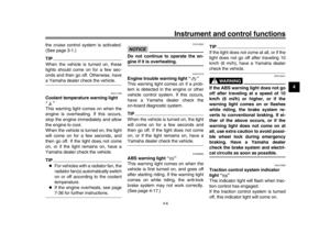 27
27 28
28 29
29 30
30 31
31 32
32 33
33 34
34 35
35 36
36 37
37 38
38 39
39 40
40 41
41 42
42 43
43 44
44 45
45 46
46 47
47 48
48 49
49 50
50 51
51 52
52 53
53 54
54 55
55 56
56 57
57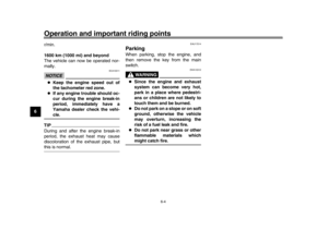 58
58 59
59 60
60 61
61 62
62 63
63 64
64 65
65 66
66 67
67 68
68 69
69 70
70 71
71 72
72 73
73 74
74 75
75 76
76 77
77 78
78 79
79 80
80 81
81 82
82 83
83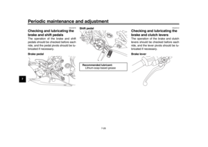 84
84 85
85 86
86 87
87 88
88 89
89 90
90 91
91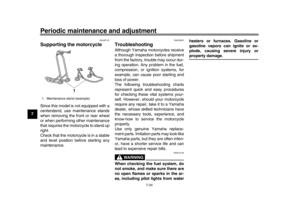 92
92 93
93 94
94 95
95 96
96 97
97 98
98 99
99 100
100 101
101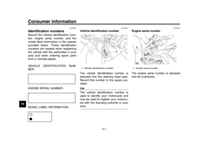 102
102 103
103 104
104 105
105 106
106 107
107
