Page 33 of 108
 turns on
and this indicator comes on.
TIPIf a problem")
Instrument and control functions
4-12
1
2
345
6
7
8
9
10
11
12
QS indicator
When the key is turned to “ON”, the
quick shift system (page 3-6) turns on
and this indicator comes on.
TIPIf a problem is detected in the quick
shift system, this indicator will turn off
and the quick shift system will be un-
available. Have a Yamaha dealercheck the vehicle.
Multi-function display
The multi-function display is equipped
with the following:
an odometer (ODO)
two tripmeters (TRIP 1 and TRIP
2)
a fuel reserve tripmeter (TRIP F)
a fuel consumption calculator
screen brightness and shift indica-
tor light control mode
TIP
The odometer will lock at 999999.
The tripmeters reset and continuecounting after 9999.9 is reached.
Push the “SELECT” switch to switch
the display between the odometer
mode “ODO”, tripmeter modes “TRIP
1” and “TRIP 2”, instantaneous fuel
consumption mode “km/L” or “L/100
km”, average fuel consumption mode
“AVE – –.– km/L” or “AVE – –.– L/100
km” in the following order:
ODO
TRIP 1 TRIP 2 km/L or
L/100 km AVE – –.– km/L or AVE
– –.– L/100 km ODO
When set to miles:
ODO TRIP 1 TRIP 2 MPG
AVE – –.– MPG ODO
If the last segment of the fuel meter
1. QS indicator
1
1. Multi-function display
1
1. Select switch “SELECT”
R ESSE T
PAS
S
TCS
SELECT
1
B67-9-E4.book 12 ページ 2019年7月19日 金曜日 午後4時23分
Page 34 of 108

Instrument and control functions
4-13
1
2
34
5
6
7
8
9
10
11
12 starts flashing, the display automatical-
ly changes to the fuel reserve tripmeter
mode “TRIP F” and starts counting the
distance traveled from that point. In this
case, push the “SELECT” switch to
switch the display in the following order:
TRIP F
km/L or L/100 km AVE
– –.– km/L or AVE – –.– L/100 km
ODO TRIP 1 TRIP 2 TRIP F
When set to miles:
TRIP F MPG AVE – –.– MPG
ODO TRIP 1 TRIP 2 TRIP F
TIP
To reset a tripmeter, select it by
pushing the “SELECT” switch, and
then push the “RESET” button for
two seconds.
If you do not reset the fuel reserve
tripmeter manually, it resets auto-
matically and disappears after re-fueling and traveling 5 km (3 mi). Instantaneous fuel consumption
mode
The instantaneous fuel consumption
display can be set to either “km/L”,
“L/100 km” or “MPG” (when the
multi-function meter unit has been
set to miles).
“km/L”: The distance that can be
traveled on 1.0 L of fuel under the
current riding conditions is shown.
“L/100 km”: The amount of fuel
necessary to travel 100 km under
the current riding conditions is
shown.
“MPG”: The distance that can be
traveled on 1.0 Imp.gal of fuel un-
der the current riding conditions is shown.
To switch between the “km/L” and
“L/100 km”, push the “CLOCK” and
“RESET” buttons at the same time.
TIPIf traveling at speeds under 20 km/h (12mi/h), “– –.–” is displayed.
Average fuel consumption mode
This display shows the average fuel
consumption since it was last reset.
The average fuel consumption display
can be set to either “AVE – –.– km/L”,
“AVE – –.– L/100 km” or “AVE – –.–
MPG” (when the multi-function meter
unit has been set to miles).
1. Instantaneous fuel consumption display
1
1. Average fuel consumption display
1
B67-9-E4.book 13 ページ 2019年7月19日 金曜日 午後4時23分
Page 35 of 108

Instrument and control functions
4-14
1
2
345
6
7
8
9
10
11
12
“AVE – –.– km/L”: The average
distance that can be traveled on
1.0 L of fuel is shown.
“AVE – –.– L/100 km”: The aver-
age amount of fuel necessary to
travel 100 km is shown.
“AVE – –.– MPG”: The average
distance that can be traveled on
1.0 Imp.gal of fuel is shown.
To switch between the “km/L” and
“L/100 km”, push the “CLOCK” and
“RESET” buttons at the same time.
To reset the average fuel consumption,
push the “RESET” button for two sec-
onds.
TIPAfter resetting the average fuel con-
sumption, “– –.–” will be shown until the
vehicle has traveled a sufficient dis-tance. Brightness and shift indicator light
control mode
This mode cycles through five control
functions, allowing you to make the fol-
lowing settings in the order listed be-
low.
Screen brightness:
This function allows you to adjust
the brightness of the screen.
Shift indicator light style:
This function allows you to set the
indicator light to on, flash, or off.
Shift indicator light on r/min:
This function allows you to select
the engine speed at which the indi-
cator light will be activated.
Shift indicator light off r/min:This function allows you to select
the engine speed at which the indi-
cator light will be deactivated.
Shift indicator light brightness:
This function allows you to adjust
the brightness of the shift indicator
light.
TIPThe brightness level display shows thebrightness level setting.
To adjust the brightness of the screen1. Turn the key to “OFF”.
2. Push and hold the “CLOCK” but-
ton.
3. Turn the key to “ON”, and then re- lease the “CLOCK” button after
five seconds.
4. Push the “RESET” button to select the desired brightness level.
5. Push the “CLOCK” button to con- firm the selected brightness level.
The control mode changes to the
shift indicator light style function.
To set the shift indicator light style1. Push the “RESET” button to select one of the following style settings:
1. Brightness level display
1
B67-9-E4.book 14 ページ 2019年7月19日 金曜日 午後4時23分
Page 36 of 108

Flash - the")
Instrument and control functions
4-15
1
2
34
5
6
7
8
9
10
11
12
On - the indicator light will come
on when activated. (This setting
is selected when the indicator
light stays on.)
Flash - the indicator light will
flash when activated. (This set-
ting is selected when the indica-
tor light flashes four times per
second.)
Off - the indicator light is deacti-
vated; in other words, it will not
come on or flash. (This setting
is selected when the indicator
light flashes once every two
seconds.)
2. Push the “CLOCK” button to con- firm the selected indicator light ac-
tivity. The control mode changes to
the shift indicator light on r/min
function.
To set the shift indicator light on r/min
TIPThe shift indicator light can be set be-
tween 7000 r/min and 13000 r/min in in-crements of 200 r/min. 1. Push the “RESET” button to select the desired engine speed for acti- vating the indicator light.
2. Push the “CLOCK” button to con- firm the selected engine speed.
The control mode changes to the
shift indicator light off r/min func-
tion.
To set the shift indicator light off r/min
TIP
The shift indicator light can be
set between 7000 r/min and
13000 r/min in increments of 200
r/min.
Be sure to set the off r/min to a
higher engine speed than the on
r/min setting, otherwise the shiftindicator light will not come on.
1. Push the “RESET” button to select the desired engine speed for deac-
tivating the indicator light.
2. Push the “CLOCK” button to con- firm the selected engine speed.
The control mode changes to the
shift indicator light brightness func-
tion. To adjust the brightness of the shift in-
dicator light1. Push the “RESET” button to select
the desired indicator light bright-
ness level.
2. Push the “CLOCK” button to con- firm the selected indicator light
brightness level and exit the bright-
ness and shift indicator light con-
trol mode.
B67-9-E4.book 15 ページ 2019年7月19日 金曜日 午後4時23分
Page 37 of 108

Instrument and control functions
4-16
1
2
345
6
7
8
9
10
11
12
EAU12822
Clutch leverThe clutch lever is located on the left
side of the handlebar. To disengage
the clutch, pull the lever toward the
handlebar grip. To engage the clutch,
release the lever. The lever should be
pulled rapidly and released slowly for
smooth clutch operation.
The clutch lever is equipped with a
clutch switch, which is part of the igni-
tion circuit cut-off system. (See
page 4-29.)
EAU76301
Shift pedalThe shift pedal is located on the left
side of the motorcycle and is used in
combination with the clutch lever when
shifting the gears of the 6-speed con-
stant-mesh transmission.
When the quick shift system is turned
on, the shift switch senses shift pedal
movement and allows for upshifting
without operating the clutch lever. (See
page 3-6.)
EAU26826
Brake leverThe brake lever is located on the right
side of the handlebar. To apply the front
brake, pull the lever toward the throttle
grip.
The brake lever is equipped with a
brake lever position adjusting dial. To
adjust the distance between the brake
lever and the throttle grip, slightly pull
the brake lever away from the throttle
grip and rotate the adjusting dial. Make
sure the setting number on the adjust-
ing dial aligns with the match mark on
1. Clutch lever
1
1. Shift pedal
1
1. Match mark
2. Brake lever position adjusting dial
3. Brake lever
4. Distance between brake lever and throttle grip
4
1 2
3
B67-9-E4.book 16 ページ 2019年7月19日 金曜日 午後4時23分
Page 38 of 108

Instrument and control functions
4-17
1
2
34
5
6
7
8
9
10
11
12 the brake lever.
EAU12944
Brake pedalThe brake pedal is located on the right
side of the motorcycle. To apply the
rear brake, press down on the brake
pedal.
EAU63040
ABSThe Yamaha ABS (Anti-lock Brake
System) features a dual electronic con-
trol system, which acts on the front and
rear brakes independently.
Operate the brakes with ABS as you
would conventional brakes. If the ABS
is activated, a pulsating sensation may
be felt at the brake lever or brake pedal.
In this situation, continue to apply the
brakes and let the ABS work; do not
“pump” the brakes as this will reduce
braking effectiveness.
WARNING
EWA16051
Always keep a sufficient distance
from the vehicle ahead to match the
riding speed even with ABS.
The ABS performs best with
long braking distances.
On certain surfaces, such as
rough or gravel roads, the brak-
ing distance may be longer withthe ABS than without.
The ABS is monitored by an ECU,
which will revert the system to conven-
tional braking if a malfunction occurs.
1. Brake pedal
1
B67-9-E4.book 17 ページ 2019年7月19日 金曜日 午後4時23分
Page 39 of 108

Instrument and control functions
4-18
1
2
345
6
7
8
9
10
11
12
TIP
The ABS performs a self-diagno-
sis test each time the vehicle first
starts off after the key is turned to
“ON” and the vehicle has traveled
at a speed of 10 km/h (6 mi/h) or
higher. During this test, a “clicking”
noise can be heard from the hy-
draulic control unit, and if the brake
lever or brake pedal is even slight-
ly applied, a vibration can be felt at
the lever and pedal, but these do
not indicate a malfunction.
This ABS has a test mode which
allows the owner to experience the
pulsation at the brake lever or
brake pedal when the ABS is oper-
ating. However, special tools are
required, so please consult yourYamaha dealer.
NOTICE
ECA20100
Be careful not to damage the wheel
sensor or wheel sensor rotor; other-
wise, improper performance of theABS will result.
EAU13076
Fuel tank capTo open the fuel tank cap
Open the fuel tank cap lock cover, in-
sert the key into the lock, and then turn
it 1/4 turn clockwise. The lock will be re-
leased and the fuel tank cap can be
opened.
To close the fuel tank cap
With the key still inserted in the lock,
push down the fuel tank cap. Turn the
key 1/4 turn counterclockwise, remove
it, and then close the lock cover.TIPThe fuel tank cap cannot be closed un-
1. Front wheel sensor rotor
2. Front wheel sensor
1. Rear wheel sensor rotor
2. Rear wheel sensor
2
12
1
1. Fuel tank cap lock cover
2. Unlock.
1
2
B67-9-E4.book 18 ページ 2019年7月19日 金曜日 午後4時23分
Page 40 of 108

Instrument and control functions
4-19
1
2
34
5
6
7
8
9
10
11
12 less the key is in the lock. In addition,
the key cannot be removed if the cap is
not properly closed and locked.
WARNING
EWA11092
Make sure that the fuel tank cap is
properly closed after filling fuel.Leaking fuel is a fire hazard.
EAU13222
FuelMake sure there is sufficient gasoline in
the tank.
WARNING
EWA10882
Gasoline and gasoline vapors are
extremely flammable. To avoid fires
and explosions and to reduce the
risk of injury when refueling, followthese instructions.
1. Before refueling, turn off the en- gine and be sure that no one is sit-
ting on the vehicle. Never refuel
while smoking, or while in the vi-
cinity of sparks, open flames, or
other sources of ignition such as
the pilot lights of water heaters and
clothes dryers.
2. Do not overfill the fuel tank. When refueling, be sure to insert the
pump nozzle into the fuel tank filler
hole. Stop filling when the fuel
reaches the bottom of the filler
tube. Because fuel expands when
it heats up, heat from the engine or
the sun can cause fuel to spill out
of the fuel tank. 3. Wipe up any spilled fuel immedi-
ately. NOTICE: Immediately wipe
off spilled fuel with a clean, dry,
soft cloth, since fuel may deteri-
orate painted surfaces or plastic
parts.
[ECA10072]
4. Be sure to securely close the fuel tank cap.
WARNING
EWA15152
Gasoline is poisonous and can
cause injury or death. Handle gaso-
line with care. Never siphon gaso-
line by mouth. If you should swallow
some gasoline or inhale a lot of gas-
oline vapor, or get some gasoline in1. Fuel tank filler tube
2. Maximum fuel level
2
1
B67-9-E4.book 19 ページ 2019年7月19日 金曜日 午後4時23分
 1
1 2
2 3
3 4
4 5
5 6
6 7
7 8
8 9
9 10
10 11
11 12
12 13
13 14
14 15
15 16
16 17
17 18
18 19
19 20
20 21
21 22
22 23
23 24
24 25
25 26
26 27
27 28
28 29
29 30
30 31
31 32
32 33
33 34
34 35
35 36
36 37
37 38
38 39
39 40
40 41
41 42
42 43
43 44
44 45
45 46
46 47
47 48
48 49
49 50
50 51
51 52
52 53
53 54
54 55
55 56
56 57
57 58
58 59
59 60
60 61
61 62
62 63
63 64
64 65
65 66
66 67
67 68
68 69
69 70
70 71
71 72
72 73
73 74
74 75
75 76
76 77
77 78
78 79
79 80
80 81
81 82
82 83
83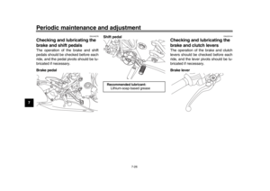 84
84 85
85 86
86 87
87 88
88 89
89 90
90 91
91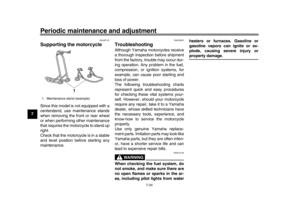 92
92 93
93 94
94 95
95 96
96 97
97 98
98 99
99 100
100 101
101 102
102 103
103 104
104 105
105 106
106 107
107