Page 41 of 108

Instrument and control functions
4-20
1
2
345
6
7
8
9
10
11
12
your eyes, see your doctor immedi-
ately. If gasoline spills on your skin,
wash with soap and water. If gaso-
line spills on your clothing, change
your clothes.
EAU75300
NOTICE
ECA11401
Use only unleaded gasoline. The use
of leaded gasoline will cause severe
damage to internal engine parts,
such as the valves and piston rings,as well as to the exhaust system.
TIP
This mark identifies the recom-
mended fuel for this vehicle as
specified by European regulation
(EN228).
Check that gasoli
ne nozzle has thesame identifier when fueling.
Your Yamaha engine has been de-
signed to use premium unleaded gaso-
line with a research octane number of
95 or higher. If knocking (or pinging) oc-
curs, use a gasoline of a different
brand. Use of unleaded fuel will extend
spark plug life and reduce maintenance
costs.
Gasohol
There are two types of gasohol: gaso- hol containing ethanol and that contain-
ing methanol. Gasohol containing
ethanol can be used if the ethanol con-
tent does not exceed 10% (E10). Gas-
ohol containing methanol is not
recommended by Yamaha because it
can cause damage to the fuel system
or vehicle performance problems.
Recommended fuel:
Premium unleaded gasoline (Gaso-
hol [E10] acceptable)
Fuel tank capacity: 17 L (4.5 US gal, 3.7 Imp.gal)
Fuel reserve amount:
4.0 L (1.06 US gal, 0.88 Imp.gal)
E5
E10
B67-9-E4.book 20 ページ 2019年7月19日 金曜日 午後4時23分
Page 42 of 108

Instrument and control functions
4-21
1
2
34
5
6
7
8
9
10
11
12
EAU72972
Fuel tank overflow hoseBefore operating the vehicle:
Check the overflow hose connec-
tion and for damage.
Confirm the overflow hose is not
blocked and is routed through the
clamp.
TIPSee page 7-10 for canister information.
EAU13434
Catalytic converterThis model is equipped with a catalytic
converter in the exhaust system.
WARNING
EWA10863
The exhaust system is hot after op-
eration. To prevent a fire hazard or
burns:
Do not park the vehicle near
possible fire hazards such as
grass or other materials that
easily burn.
Park the vehicle in a place
where pedestrians or children
are not likely to touch the hot
exhaust system.
Make sure that the exhaust sys-
tem has cooled down before do-
ing any maintenance work.
Do not allow the engine to idle
more than a few minutes. Long
idling can cause a build-up ofheat.
NOTICE
ECA10702
Use only unleaded gasoline. The use
of leaded gasoline will cause unre- pairable damage to the catalytic
converter.
1. Clamp
2. Fuel tank overflow hose
1
2
B67-9-E4.book 21 ページ 2019年7月19日 金曜日 午後4時23分
Page 43 of 108

Instrument and control functions
4-22
1
2
345
6
7
8
9
10
11
12
EAU57992
SeatTo remove the seat 1. Open the seat lock cover, insert the key into the seat lock, and then
turn the key counterclockwise.
2. While holding the key in that posi- tion, slide the seat backward and
then lift the rear of the seat up, and
then pull the seat off.
To install the seat 1. Insert the projections into the seat holders as shown. 2. Push the rear of the seat down to
lock it in place.
3. Remove the key.
TIPMake sure that the seat is properly se-cured before riding.
EAU70412
Adjusting the front forkThis model is equipped with adjustable
suspension. The spring preload, re-
bound damping force, and compres-
sion damping force of each leg can be
adjusted.
WARNING
EWA10181
Always adjust both fork legs equal-
ly, otherwise poor handling and lossof stability may result.NOTICE
ECA22471
Use extra care to avoid scratch-
ing the gold-anodized finish
when making suspension ad-
justments.
To avoid damaging the suspen-
sion’s internal mechanisms, do
not attempt to turn beyond themaximum or minimum settings.
Spring preload
To increase the spring preload and
thereby harden the suspension, turn
the adjusting nut on each fork in direc-
tion (a). To decrease the spring preload
1. Seat lock cover
2. Seat lock
3. Unlock.
2 3
1
1. Projection
2. Seat holder
2
2 1
B67-9-E4.book 22 ページ 2019年7月19日 金曜日 午後4時23分
Page 44 of 108
.
Rebound damping force
To increase the rebound")
Instrument and control functions
4-23
1
2
34
5
6
7
8
9
10
11
12 and thereby soften the suspension,
turn the adjusting nut on each fork in di-
rection (b).
Rebound damping force
To increase the rebound damping force
and thereby harden the rebound damp-
ing, turn the adjusting bolt on each fork
leg in direction (a). To decrease the re-
bound damping force and thereby soft- en the rebound damping, turn the
adjusting bolt on each fork leg in direc-
tion (b).
Compression damping force
To increase the compression damping
force and thereby harden the compres-
sion damping, turn the adjusting bolt on
each fork leg in direction (a). To de-
crease the compression damping forceand thereby soften the compression
damping, turn the adjusting bolt on
each fork leg in direction (b).
TIP
When turning a damping force ad-
juster in direction (a), the 0 click
position and the 1 click position
may be the same.
Although a damping force adjuster
1. Spring preload adjusting nutSpring preload setting:
Minimum (soft):
0 turn(s) in direction (a)
Standard: 9 turn(s) in direction (a)
Maximum (hard): 15 turn(s) in direction (a)
after fully turning in direction (b)
1
(a) (b)
1. Rebound damping force adjusting boltRebound damping setting:
Minimum (soft):
14 click(s) in direction (b)
Standard: 6 click(s) in direction (b)
Maximum (hard): 1 click(s) in direction (b)
after fully turning in direction (a)
1
(a) (b)
1. Compression damping force adjusting boltCompression damping setting:
Minimum (soft):
23 click(s) in direction (b)
Standard: 17 click(s) in direction (b)
Maximum (hard): 1 click(s) in direction (b)
after fully turning in direction (a)
1
(a) (b)
B67-9-E4.book 23 ページ 2019年7月19日 金曜日 午後4時23分
Page 45 of 108

Instrument and control functions
4-24
1
2
345
6
7
8
9
10
11
12
may turn or click beyond the stated
minimum settings, such adjust-
ments are ineffective and may
damage the suspension.
EAU74241
Adjusting the shock absorber
assemblyThis model is equipped with adjustable
suspension. The spring preload, re-
bound damping force, fast compres-
sion damping force, and slow
compression damping force can be ad-
justed.NOTICE
ECA10102
To avoid damaging the mechanism,
do not attempt to turn beyond themaximum or minimum settings.
Spring preload
1. Loosen the locknut.
2. To increase the spring preload and thereby harden the suspension,
turn the adjusting ring in direction
(a). To decrease the spring pre-
load and thereby soften the sus-
pension, turn the adjusting ring in
direction (b).
The spring preload setting is deter-
mined by measuring distance A.
The longer distance A is, the high-
er the spring preload; the shorter distance A is, the lower the spring
preload.
Use the special wrench includ-
ed in the additional tool kit to
make the adjustment.
1. Spring preload adjusting ring
2. Locknut
3. Special wrench
1. Distance A
(a)
(b)1
2
3
1
B67-9-E4.book 24 ページ 2019年7月19日 金曜日 午後4時23分
Page 46 of 108

Instrument and control functions
4-25
1
2
34
5
6
7
8
9
10
11
12 3. Tighten the locknut to the specified
torque. NOTICE: Always tighten
the locknut against the adjust-
ing ring, and then tighten the
locknut to the specified
torque.
[ECA22760]
Rebound damping force
To increase the rebound damping force
and thereby harden the rebound damp-
ing, turn the adjusting screw in direction
(a). To decrease the rebound damping
force and thereby soften the rebound
damping, turn the adjusting screw in di-
rection (b). Compression damping force
Fast compression damping force
To increase the compression damping
force and thereby harden the fast com-
pression damping, turn the adjusting
bolt in direction (a). To decrease the
compression damping force and there-by soften the compression damping,
turn the adjusting bolt in direction (b).
Slow compression damping force
To increase the compression damping
force and thereby harden the slow
compression damping, turn the adjust-
ing screw in direction (a). To decrease
Spring preload:
Minimum (soft):Distance A = 77.5 mm (3.05 in)
Standard:
Distance A = 81.5 mm (3.21 in)
Maximum (hard): Distance A = 85.5 mm (3.37 in)
Tightening torque: Locknut:25 N·m (2.5 kgf·m, 18 lb·ft)
1. Rebound damping force adjusting screwRebound damping setting: Minimum (soft):
23 click(s) in direction (b)*
Standard: 11 click(s) in direction (b)*
Maximum (hard): 1 click(s) in direction (b)*
* With the adjusting screw fully turned
in direction (a)(a) (b)
1
1. Fast compression damping force
adjusting bolt Fast compression damping settingMinimum (soft):
5.5 turn(s) in direction (b)*
Standard: 3 turn(s) in direction (b)*
Maximum (hard): 0 turn(s) in direction (b)*
* With the adjusting bolt fully turned in
direction (a)
(a) (b)
1
B67-9-E4.book 25 ページ 2019年7月19日 金曜日 午後4時23分
Page 47 of 108
.
TIP
When turnin")
Instrument and control functions
4-26
1
2
345
6
7
8
9
10
11
12
the compression damping force and
thereby soften the compression damp-
ing, turn the adjusting screw in direction
(b).
TIP
When turning a damping force ad-
juster in direction (a), the 0 click
position and the 1 click position may be the same.
Although a damping force adjuster
may turn or click beyond the stated
minimum settings, such adjust-
ments are ineffective and maydamage the suspension.WARNING
EWA10222
This shock absorber assembly con-
tains highly pressurized nitrogen
gas. Read and understand the fol-
lowing information before handling
the shock absorber assembly.
Do not tamper with or attempt to
open the cylinder assembly.
Do not subject the shock ab-
sorber assembly to an open
flame or other high heat source.
This may cause the unit to ex-
plode due to excessive gas
pressure.
Do not deform or damage the
cylinder in any way. Cylinder
damage will result in poor
damping performance.
Do not dispose of a damaged or
worn-out shock absorber as-
sembly yourself. Take the shock
absorber assembly to a Yamaha
dealer for any service.
1. Slow compression damping force
adjusting screwSlow compression damping settingMinimum (soft):
18 click(s) in direction (b)*
Standard: 12 click(s) in direction (b)*
Maximum (hard): 1 click(s) in direction (b)*
* With the adjusting screw fully turned
in direction (a)
(a) (b)
1
B67-9-E4.book 26 ページ 2019年7月19日 金曜日 午後4時23分
Page 48 of 108

Instrument and control functions
4-27
1
2
34
5
6
7
8
9
10
11
12
EAU15152
Luggage strap holdersThere is a luggage strap holder on each
passenger footrest.
EAU67050
EXUP systemThis model is equipped with Yamaha’s
EXUP (EXhaust Ultimate Power valve)
system. This system boosts engine
power by means of a valve that controls
exhaust flow within the exhaust cham-
ber.NOTICE
ECA15611
The EXUP system has been set and
extensively tested at the Yamaha
factory. Changing these settings
without sufficient technical knowl-
edge may result in poor perfor-mance of or damage to the engine.
EAU49454
Auxiliary DC jackA 12-V accessory connected to the
auxiliary DC jack can be used when the
main switch is on.NOTICE
ECA15432
The accessory connected to the
auxiliary DC jack should not be used
with the engine turned off, and the
load must never exceed 12 W (1.0 A),
otherwise the fuse may blow or thebattery may discharge.
To use the auxiliary DC jack 1. Turn the main switch off.
2. Remove the auxiliary DC jack cap.
1. Luggage strap holder
1
1. Auxiliary DC jack cap
1
B67-9-E4.book 27 ページ 2019年7月19日 金曜日 午後4時23分
 1
1 2
2 3
3 4
4 5
5 6
6 7
7 8
8 9
9 10
10 11
11 12
12 13
13 14
14 15
15 16
16 17
17 18
18 19
19 20
20 21
21 22
22 23
23 24
24 25
25 26
26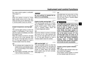 27
27 28
28 29
29 30
30 31
31 32
32 33
33 34
34 35
35 36
36 37
37 38
38 39
39 40
40 41
41 42
42 43
43 44
44 45
45 46
46 47
47 48
48 49
49 50
50 51
51 52
52 53
53 54
54 55
55 56
56 57
57 58
58 59
59 60
60 61
61 62
62 63
63 64
64 65
65 66
66 67
67 68
68 69
69 70
70 71
71 72
72 73
73 74
74 75
75 76
76 77
77 78
78 79
79 80
80 81
81 82
82 83
83 84
84 85
85 86
86 87
87 88
88 89
89 90
90 91
91 92
92 93
93 94
94 95
95 96
96 97
97 98
98 99
99 100
100 101
101 102
102 103
103 104
104 105
105 106
106 107
107