2020 VOLKSWAGEN TRANSPORTER light
[x] Cancel search: lightPage 206 of 486

Symbol Meaning
A Flow of electric current in amps
Lit up: 230-volt mains connection has been made and the battery charger is working. Flashing or displaying a number over 15 volts: malfunction. Disconnect the 230-volt mains connection and have the electrical system checked by a qualified workshop. Not lit up despite a 230-volt connection being made: there is a power cut or malfunction in the battery charger.
G The batteries are being charged by the alternator.
Warning messages
Under certain conditions, such as when the pop-up roof is open, warning messages appear on the dis-play when the engine is started. These warn against possible vehicle or equipment damage.
• Switch off the ignition and correct the cause of the warning message.
Malfunction
If a symbol flashes, there is a fault in the indicated system.
• Press the button G?) for five seconds to clear the fault. If this does not work or if other faults ap-pear, please contact a qualified workshop. Volks-wagen Commercial Vehicles recommends using a Volkswagen Commercial Vehicles dealership for this purpose.
A WARNING
Failure to observe illuminated warning lamps and text messages can lead to your vehicle breaking down in traffic, and can cause acci-dent and serious injury.
A WARNING (Continued)
• Never Ignore any Illuminated warning lamps or text messages.
• Stop the vehicle as soon as possible and when safe to do so.
• Stop the vehicle at a safe distance away from moving traffic and ensure that no part of the exhaust system can come Into contact with any Inflammable material underneath the vehicle, e.g. dry grass or fuel.
• Any broken-down vehicle poses an In-creased accident risk both for you and for other road users. If the situation requires, switch on the hazard warning lights and set up the warning triangle as a warning to other road users.
• Before opening the bonnet, switch off the engine and allow it to cool down sufficiently.
• The engine compartment of any motor ve-hicle is a dangerous area. Serious injuries can be sustained here 350.
CD
Failure to observe illuminated indicator lamps and text messages can lead to your vehicle be-ing damaged.
J'"'""'('n First read and observe the introductory L-J,:.IJ information given on page 204.
Main menu Possible functions
Pop-up roof Opening
Closing
Displays Outside temperature
206 Before the journey
Using the menus
• Turn the rotary/push knob 168@ to highlight a function or submenu or to change a set-ting.
• Press the rotary/push knob to select a function or submenu or to confirm a setting.
Description of the submenu with examples
Open the pop-up roof .,1
Close the pop-up roof .,t
Current outside temperature (28.SO C) ...
Page 208 of 486
• Select New.
• Change the flashing figures by turning the knob 168 @) and press the knob to confirm.
Deleting the countdown timer
• Use the rotary/push knob to select the count-down timer.
• Select Delete and confirm by selecting Yes.
Changing the countdown timer setting
• Select New.
• Change the flashing figures by turning the knob 168@) and press the knob to confirm. The old countdown timer setting is automatically over-written.
Interior lights, California
CClJ Introduction
This chapter contains information on the following subjects:
Interior lights in the living area . . . . • . • . . . . . . 209
Interior lights in the pop-up roof . . . . . . . . . . . 210
Additional information:
• Electrical sockets 163
• Battery 350
208 Before the journey
Turning off the countdown timer
• Press the (2) button.
W The stored countdown timer setting is deleted L!J if the central control panel is switched off. <
• Cigarette lighter 163
• Accessories, modifications, repairs and renewal of parts 394
• Fuses 429
• Consumer information 404
• Rectifying faults on the camping equipment 254
Page 209 of 486
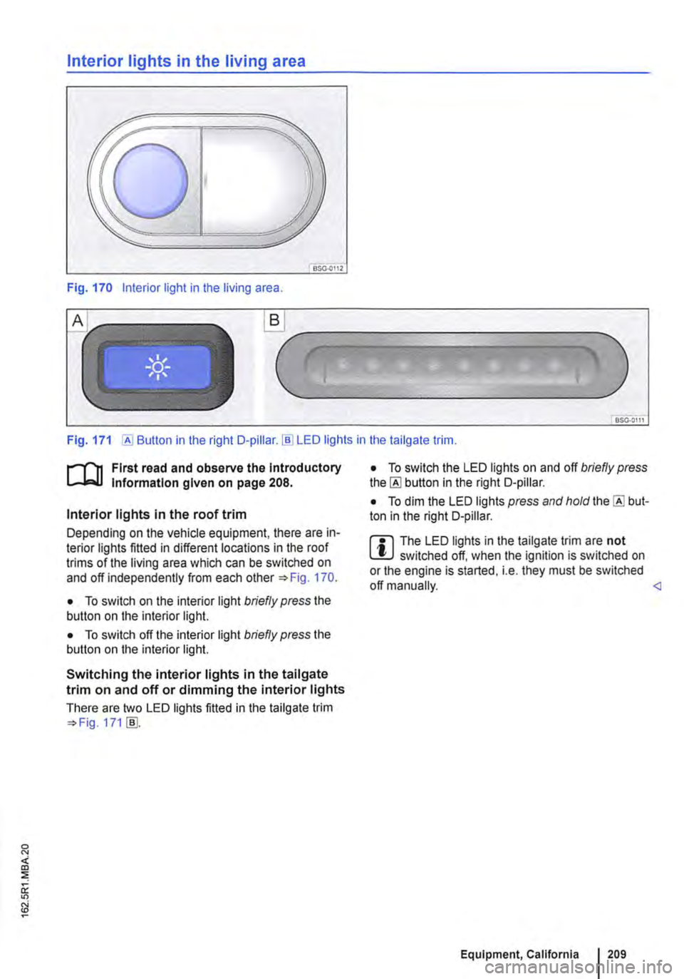
Interior lights in the living area
OSG.OI12
Fig. 170 Interior light in the living area .
.._______)
Fig. 171 [AI Button in the right D-pillar.!ID LED lights in the tailgate trim.
r-1'11 First read and observe the Introductory t.....J,..,lJ Information given on page 208.
Interior lights in the roof trim
Depending on the vehicle equipment, there are in-terior lights fitted in different locations in the roof trims of the living area which can be switched on and off independently from each other 170.
• To switch on the interior light briefly press the button on the interior light.
• To switch off the interior light briefly press the button on the interior light.
Switching the interior lights in the tailgate trim on and off or dimming the interior lights
There are two LED lights fitted in the tailgate trim 171 [ID.
• To switch the LED lights on and off briefly press the [AI button in the right D-pillar.
• To dim the LED lights press and hold the [AI but-ton in the right D-pillar.
m The LED lights in the tailgate trim are not W switched off, when the ignition is switched on or the engine is started, i.e. they must be switched off manually.
Page 210 of 486
Interior lights in the pop-up roof
___ )
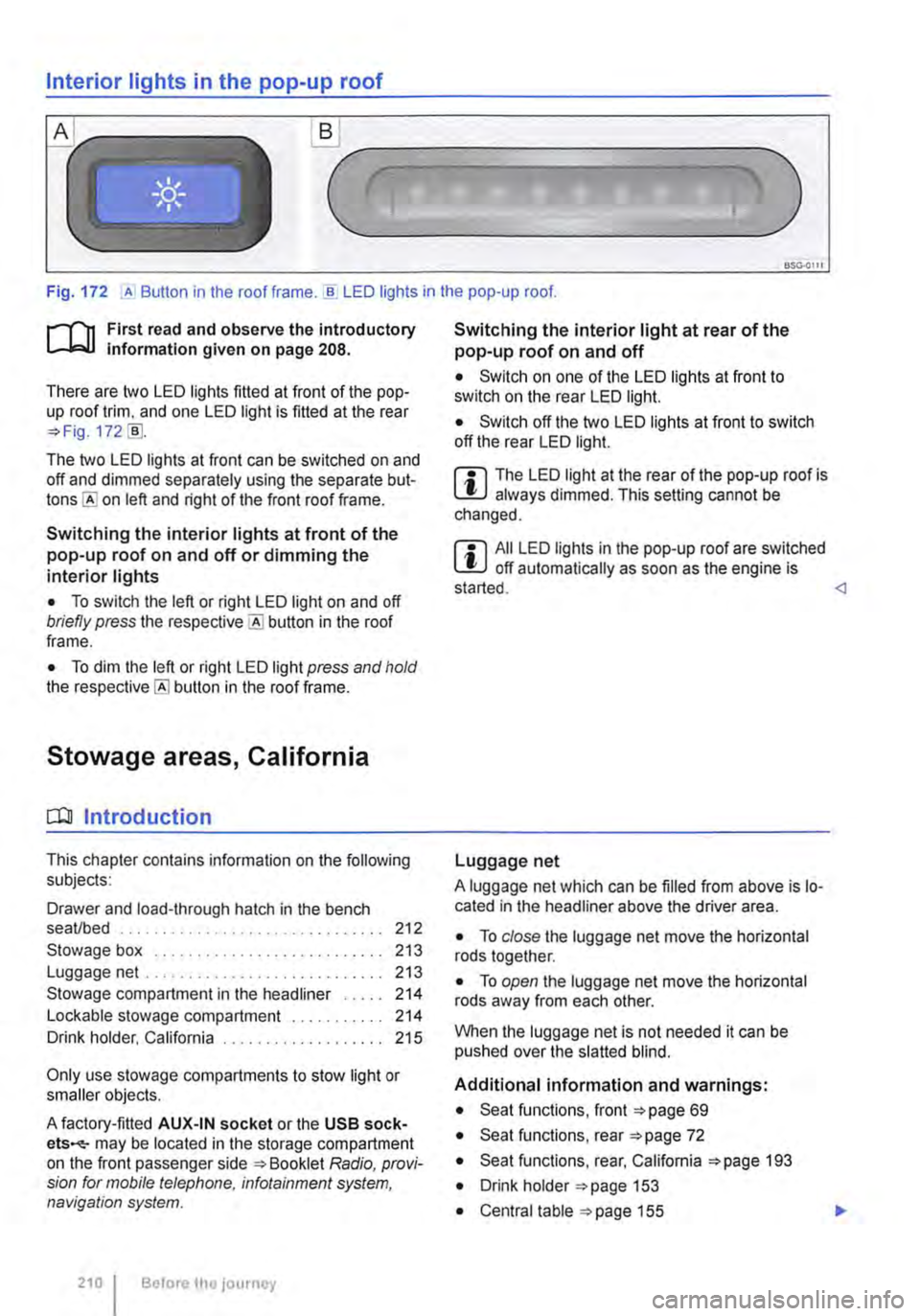
Fig. 172 ,A Button in the roof frame . ..!!. LED lights in the pop-up roof.
r--T'n First read and observe the introductory L-lcJ.I information given on page 208.
There are two LED lights fitted at front of the pop-up roof trim, and one LED light is fitted at the rear =?Fig. 172 [ID.
The two LED lights at front can be switched on and off and dimmed separately using the separate but-on left and right of the front roof frame.
Switching the interior lights at front of the pop-up roof on and off or dimming the interior lights
• To switch the left or right LED light on and off briefly press the button in the roof frame.
• To dim the left or right LED light press and hold the button in the roof frame.
Stowage areas, California
CQJ Introduction
This chapter contains information on the following subjects:
Drawer and load-through hatch in the bench seaVbed . . . . . . . . . . . . . . . . 212
Stowage box . . . . . . . . . . . . . . . . . . . 213 Luggage net .. .. .. . .. .. . 213
Stowage compartment in the headliner . . . . . 214 Lockable stowage compartment . . 214 Drink holder, California . . . . . . . . . . . 215
Only use stowage compartments to stow light or smaller objects.
A factory-fitted AUX-IN socket or the USB sock-ets-may be located in the storage compartment on the front passenger side =?Booklet Radio, provi-sion for mobile telephone, infotainment system, navigation system.
210 I Before the journey
Switching the interior light at rear of the pop-up roof on and off
• Switch on one of the LED lights at front to switch on the rear LED light.
• Switch off the two LED lights at front to switch off the rear LED light.
m The LED light at the rear of the pop-up roof is W always dimmed. This setting cannot be changed.
m All LED lights in the pop-up roof are switched W off automatically as soon as the engine is started.
A luggage net which can be filled from above is lo-cated in the headliner above the driver area.
• To close the luggage net move the horizontal rods together.
• To open the luggage net move the horizontal rods away from each other.
When the luggage net is not needed it can be pushed over the slatted blind.
Additional information and warnings:
• Seat functions, front =?page 69
• Seat functions, rear =?page 72
• Seat functions, rear, California =?page 193
• Drink holder =?page 153
• Central table =?page 155
Page 211 of 486
• Stowage page 1 50
• Cleaning and caring for the interior 388
A WARNING
Loose objects may be flung through the vehi-cle interior in the event of a sudden driving or braking manoeuvre. This can cause serious injury and can also lead to loss of control of the vehicle.
• Do not stow any pets or any hard, heavy or sharp objects in the vehicle's open stow-age compartments, in the luggage net, on the dash panel, on the shelf behind the rear seats or in items of clothing and bags in the vehicle interior.
• Always keep stowage compartments closed while the vehicle is in motion.
A WARNING
Objects in the driver footweli can hinder ped-al operation. This can lead to loss of control of the vehicle and increase the risk of serious injury.
• Please ensure that all pedals can always be operated without any hindrance.
• The foot mats must always be properly se-cured in the footwell.
• No additional foot mats or other floor cov-erings should be placed over the fitted foot mat.
• Ensure that no objects can enter the driv-er footwell while the vehicle is in motion.
• If there are any objects in the footwell, re-move them when the vehicle is parked.
A WARNING
Improper use of the stowage compartments can cause serious injury.
• Never fill stowage compartments beyond their capacity.
A WARNING (Continued)
• Always take care when closing stowage compartments that nobody is within their functional area.
A WARNING
Cigarette lighters in the vehicle could be damaged or accidentally lit. This could lead to serious burns and other injuries.
• Before adjusting the seats always make sure that there is no lighter on or near the moveable parts of the seat.
• Before closing stowage areas or compart-ments always ensure that there is no lighter in the way.
• Never stow lighters in stowage areas or compartments or on other surfaces in the ve-hicle. Cigarette lighters may self-ignite on high-temperature surfaces, especially in sum-mer.
CD
• Hard objects on the shelf can chafe against the wires of the heating element in the rear win-dow and cause damage.
• Do not store any heat-sensitive objects, food or medicines inside the vehicle. Hot and cold temperatures could damage them or ren-der them unusable.
• Objects stored in the vehicle that are made from transparent materials, such as glasses, magnifying glasses or transparent suction cups on the windows, can concentrate the sun's rays and thus cause damage to the vehi-cle.
m Always ensure that the ventilation openings L!J between the rear window and the stowage area are uncovered to allow stale air to escape from the vehicle.
Page 213 of 486
Stowage box
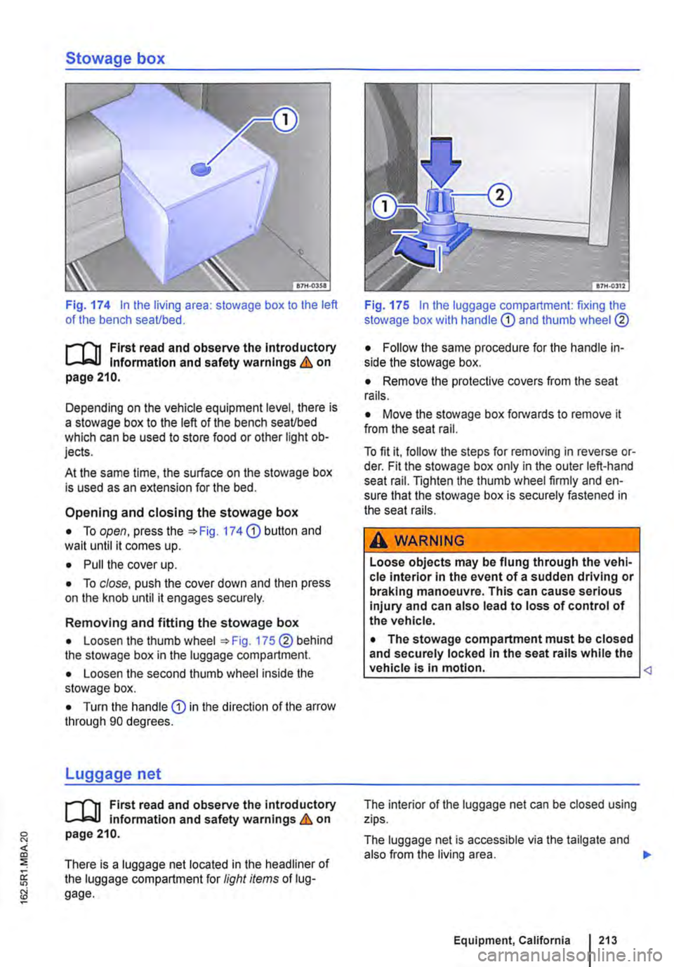
Fig. 174 In the living area: stowage box to the left of the bench seaUbed.
f""'"'('n First read and observe the lntrod uctory L-J,:.,LJ Information and safety warnings & on page 210.
Depending on the vehicle equipment level, there is a stowage box to the left of the bench seaUbed which can be used to store food or other light ob-jects.
At the same time, the surface on the stowage box is used as an extension for the bed.
Opening and closing the stowage box
• To open, press the :;. Fig. 174 (D button and wait until it comes up.
• Pull the cover up.
• To close, push the cover down and then press on the knob until it engages securely.
Removing and fitting the stowage box
• Loosen the thumb wheel :;. Fig. 175 ®behind the stowage box in the luggage compartment.
• Loosen the second thumb wheel inside the stowage box.
• Turn the handle (D in the direction of the arrow through 90 degrees.
Luggage net
f""'"'('n First read and observe the introductory L..-Wl Information and safety warnings & on page 210.
There is a luggage net located in the headliner of the luggage compartment for light items of lug-gage.
Fig. 175 In the luggage compartment: fixing the stowage box with handle
• Remove the protective covers from the seat rails.
• Move the stowage box forwards to remove it from the seat rail.
To fit it, follow the steps for removing in reverse or-der. Fit the stowage box only in the outer left-hand seat rail. Tighten the thumb wheel firmly and en-sure that the stowage box is securely fastened in the seat rails.
A WARNING
Loose objects may be flung through the vehi-cle interior in the event of a sudden driving or braking manoeuvre. This can cause serious injury and can also lead to loss of control of the vehicle.
• The stowage compartment must be closed and securely locked In the seat rails while the vehicle Is In motion.
The luggage net is accessible via the tailgate and also from the living area. .,..
Equipment, California I 213
Page 215 of 486
Drink holder, California
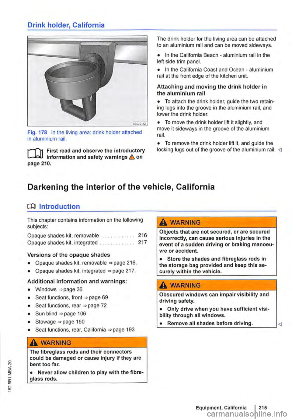
Fig. 178 In the living area: drink holder attached in aluminium rail.
.--m First read and observe the introductory information and safety warnings & on page 210.
The drink holder for the living area can be attached to an aluminium rail and can be moved sideways.
• In the California Beach -aluminium rail in the left side trim panel.
• In the California Coast and Ocean -aluminium rail at the front edge of the kitchen unit.
Attaching and moving the drink holder in the aluminium rail
• To attach the drink holder, guide the two retain-ing lugs into the groove in the aluminium rail, and lower the drink holder.
• To move the drink holder lift it slightly. and move it sideways in the groove of the aluminium rail.
• To remove the drink holder lift it, and guide the locking lugs out of the groove of the aluminium rail.
CC!J Introduction
This chapter contains information on the following subjects:
Opaque shades kit, removable
Opaque shades kit, integrated
Versions of the opaque shades
• Opaque shades kit, removable =>page 216.
• Opaque shades kit, integrated =>page 217.
Additional information and warnings:
• Windows =>page 36
• Seat functions, front =>page 69
• Seat functions, rear =>page 72
• Sun blind =>page 106
• Stowage =>page 150
• Seat functions, rear, California =>page 193
A WARNING
216 217
The fibreglass rods and their connectors could be damaged or cause injury if they are bent too far.
• Never allow children to play with the fibre-glass rods.
A WARNING
Objects that are not secured, or are secured Incorrectly, can cause serious injuries in the event of a sudden driving or braking manoeu-vre or accident.
• Store the shades and fibreglass rods in the storage bag provided and keep this se-curely within the vehicle.
A WARNING
Obscured windows can impair visibility and driving safety.
• Only drive when you have sufficient visi-bility through all windows.
• Remove all shades before driving.
Page 217 of 486
Opaque shades kit, integrated
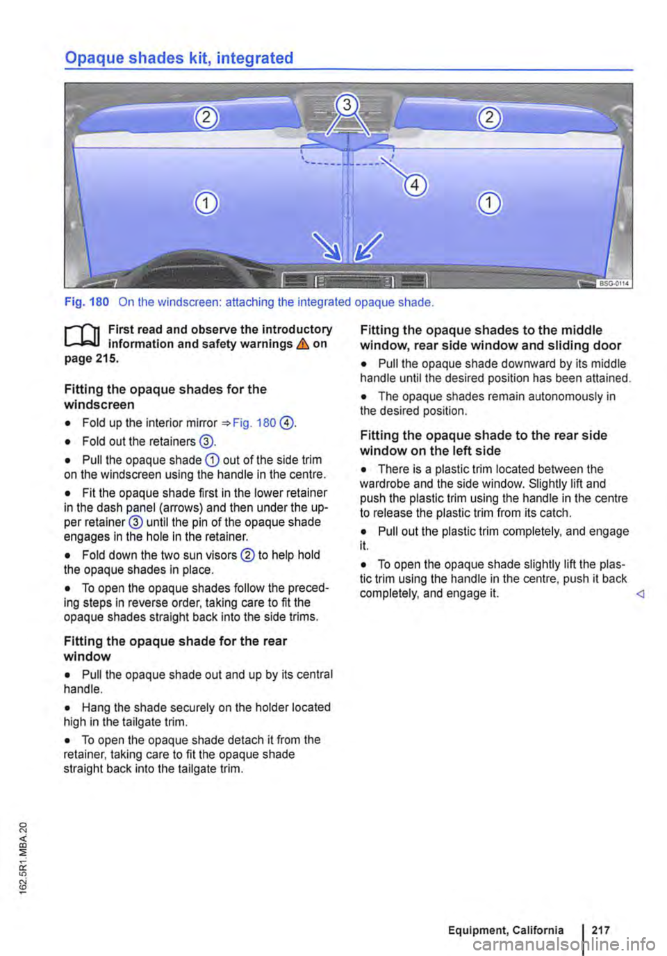
Fig. 180 On the windscreen: attaching the integrated opaque shade.
f""""'('n First read and observe the introductory L-W.I information and safety warnings & on page 215.
Fitting the opaque shades for the windscreen
• Fold up the interior mirror 180 @.
• Fold out the retainers@.
• Pull the opaque shade CD out of the side trim on the windscreen using the handle in the centre.
• Fit the opaque shade first in the lower retainer in the dash panel (arrows) and then under the up-per retainer@ until the pin of the opaque shade engages In the hole in the retainer.
• Fold down the two sun visors ®to help hold the opaque shades in place.
• To open the opaque shades follow the preced-ing steps in reverse order, taking care to fit the opaque shades straight back Into the side trims.
Fitting the opaque shade for the rear window
• Pull the opaque shade out and up by its central handle.
• Hang the shade securely on the holder located high in the tailgate trim.
• To open the opaque shade detach it from the retainer, taking care to fit the opaque shade straight back into the tailgate trim.
Fitting the opaque shades to the middle window, rear side window and sliding door
• Pull the opaque shade downward by its middle handle until the desired position has been attained.
• The opaque shades remain autonomously in the desired position.
Fitting the opaque shade to the rear side window on the left side
• There is a plastic trim located between the wardrobe and the side window. Slightly lift and push the plastic trim using the handle in the centre to release the plastic trim from its catch.
• Pull out the plastic trim completely, and engage it.
• To open the opaque shade slightly lift the plas-tic trim using the handle in the centre, push it back completely, and engage it.