2020 VOLKSWAGEN TRANSPORTER light
[x] Cancel search: lightPage 223 of 486
Closing the electric pop-up roof
j'"'('n First read and observe the introductory information and safety warnings & on page 221.
• Close all of the windows in the pop-up roof can-vas.
• Remove the children's safety net.
• Lower the bed panel.
• Ensure that the roller shutter is and stays open.
• Make sure that no people or objects, such as blankets or pillows, are on the upper bed. Position the mattress correctly.
• Disconnect any connected devices from the 12-volt socket in the roof frame, and stow them in a safe place in the vehicle.
• Switch on the ignition.
• Open one of the vehicle doors to allow excess air pressure to escape.
• Switch on the central control panel.
• Select the menu option Pop-up roof in the central control panel.
• Select menu option Close (dark background).
• Press and hold the rotary/push knob for ap-proximately four seconds. An acoustic signal is giv-en and the display reads for approximately four seconds Roof bed down? Shutter open? Window open?. All control elements for the pop-up roof are blocked during this safety check.
• Press and hold the rotary/push knob again to continue closing. Make sure that the canvas is not pinched at the front or on the side between the ve-hicle and the roof or the rods.
• Press and hold the rotary/push knob until the hydraulic motor has switched off automatically and the pop-up roof has closed fully. This is shown by the .t symbol in the display. The hydraulic motor has a run-on time of approx. 5 seconds to bleed the hydraulic system.
• Close the roller shutter. Make sure that the can-vas is not pinched.
m The LED lights in the pop-up roof are switch-L!..J ed off automatically as soon as the engine is
Equipment, California I 223
Page 224 of 486
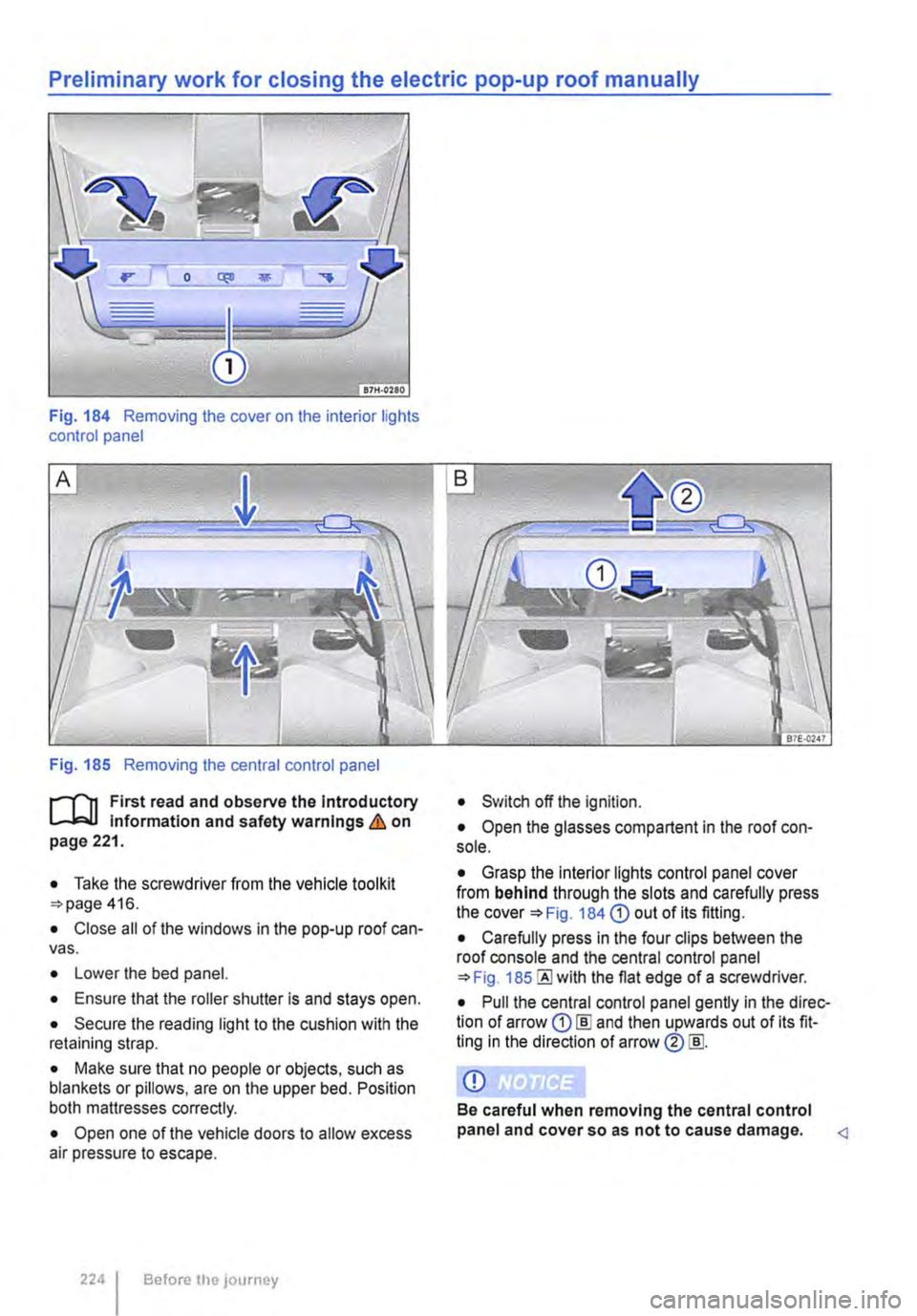
Preliminary work for closing the electric pop-up roof manually
Fig. 184 Removing the cover on the interior lights control panel
Fig. 185 Removing the central control panel
r-T'n First read and observe the Introductory L-W.l Information and safety warnings & on page 221.
• Take the screwdriver from the vehicle tool kit 416.
• Close all of the windows in the pop-up roof can-vas.
• Lower the bed panel.
• Ensure that the roller shutter is and stays open.
• Secure the reading light to the cushion with the retaining strap.
• Make sure that no people or objects, such as blankets or pillows, are on the upper bed. Position both mattresses correctly.
• Open one of the vehicle doors to allow excess air pressure to escape.
224 I Before the journey
• Switch off the ignition.
• Open the glasses compartent in the roof con-sole.
• Grasp the interior lights control panel cover from behind through the slots and carefully press the Fig. 184 CD out of its fitting.
• Carefully press in the four clips between the roof console and the central control panel 185 the flat edge of a screwdriver.
• Pull the central control panel gently in the direc-tion of arrow CD [ID and then upwards out of its fit-ting in the direction of arrow ®[ID.
CD
Be careful when removing the central control panel and cover so as not to cause damage.
Page 230 of 486
Assembling the folding table inside the vehicle
• Press handle 192 G) to unlock the fold-ing table.
• Lift the folding table out of its retainer.
• Pull the table guides 193@ right out.
• Connect the table guides to the guide rails on the side wall opposite the sliding door. To do this, guide the table guide from above into the groove in the rail, holding the folding table horizontally.
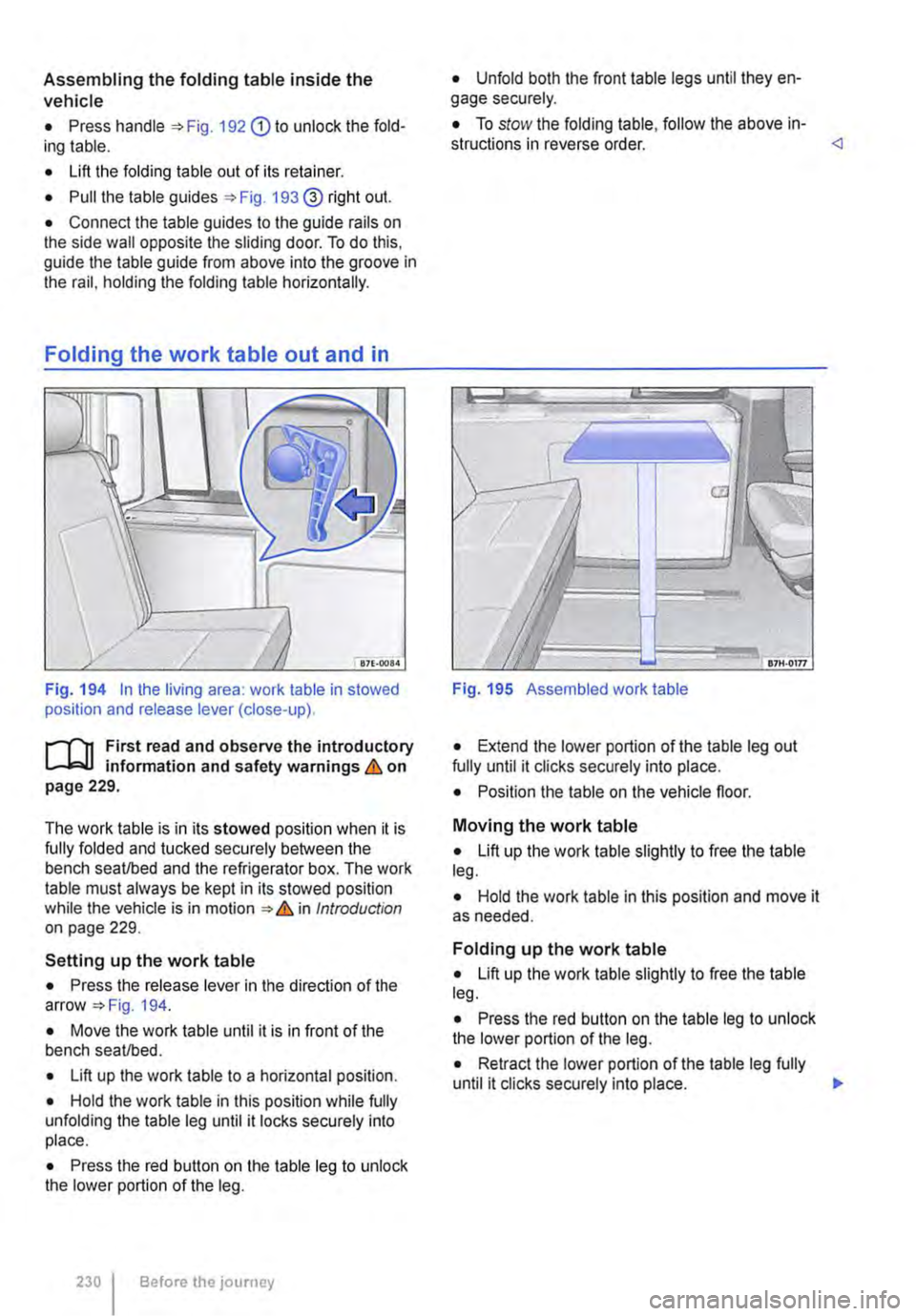
Fig. 194 In the living area: work table in stowed position and release lever (close-up).
1""1'11 First read and observe the introductory L-J,:.,U information and safety warnings & on page 229.
The work table is in its stowed position when it is fully folded and tucked securely between the bench seat/bed and the refrigerator box. The work table must always be kept in its stowed position while the vehicle is in motion & in Introduction on page 229.
Setting up the work table
• Press the release lever in the direction of the arrow 194.
• Move the work table until it is in front of the bench seat/bed.
• Lift up the work table to a horizontal position.
• Hold the work table in this position while fully unfolding the table leg until it locks securely into place.
• Press the red button on the table leg to unlock the lower portion of the leg.
230 Before the journey
• Unfold both the front table legs until they en-gage securely.
• To stow the folding table, follow the above in-structions in reverse order.
Fig. 195 Assembled work table
• Extend the lower portion of the table leg out fully until it clicks securely into place.
• Position the table on the vehicle floor.
Moving the work table
• Lift up the work table slightly to free the table leg.
• Hold the work table in this position and move it as needed.
Folding up the work table
• Lift up the work table slightly to free the table leg.
• Press the red button on the table leg to unlock the lower portion of the leg.
• Retract the lower portion of the table leg fully until it clicks securely into place. 11>
Page 237 of 486
• Keep the knob pressed in for approx. 15 sec-onds to temporarily bridge the igniter safety device. If you let go of the knob too quickly, the gas flame goes out. If this occurs, re-light the burner as de-scribed above.
• Release the regulating knob and adjust the gas flame as required.
Turning off the gas flame
• Turn the appropriate knob@ fully clockwise to turn off the gas flame.
• Close the gas shut-off valve in the kitchen unit.
• Close the safety valve on the gas bottle.
• Remove all objects from the gas cooker and al-low the cooker to cool fully.
• Place the backrest of the left front seat in an upright position or turn the left front seat so that you can close the kitchen unit's cover plate.
• Lower the kitchen unit cover plate and latch it securely. <1
Water supply and disposal, California
n::n Introduction
This chapter contains information on the following subjects:
Fresh water system . . . . . . . . . . . . . . . . . . . . . . 238
Sterilising agent . . . . . . . . . . . . . . . . • . . . . . . . . 239
Cleaning the fresh water tank . . . . . . . . . . . . . 239 Waste water tank . . . . . . . . . . . . . . . . . . . . . . . . 240
Turning the water on and off . . . . . . . . . . . . . . 240
Cleaning the drain . . . . . . . . . . . . . . . . . . . . . . . 241
Additional information:
• Central control panel 204
• Rectifying faults on the camping equipment 254
• Fuses for the camping equipment 249
• Winter conditions 253
• Filling the tank 340
A WARNING
Improper use of the fresh water system can lead to poisoning and illness.
• The fresh water tank should only be filled with drinking water from the public water supply.
• Never fill the fresh water tank from springs or streams. Such water could be con-taminated or contain debris.
• Never use commercially available house-hold cleaners to clean the fresh water tank.
• Never leave water in the fresh water tank for long periods without replacing it with fresh water.
,A WARNING (Continued)
• Drain the fresh water system completely when it will not be used for a long time.
A WARNING
Both the fresh water tank and the waste water tank drain out underneath the vehicle. In very cold conditions this poses a danger from the formation of ice.
• Be especially careful when fresh or waste water are drained during freezing or very cold weather.
CD
In very cold weather the fresh and waste water systems should be emptied to prevent them from becoming damaged if the vehicle is not to be kept heated continuously or Is only to be used for short periods.
CD
Do not allow the water pump to run dry as this will damage the pump.
• Only switch on the water pump when there Is water in the fresh water tank.
m if you do not use the sink for a long period' it L.:!J should be kept dry and free of salt.
m Never confuse the fresh water tank filler neck L.:!J with the fuel tank filler neck. <1
Equipment, California 237
Page 242 of 486
Using the refrigerator box
r--('n First read and observe the introductory information and safety warnings & on page 241.
The suspended basket in the refrigerator box is for cooling food. The temperature is lower under the basket than inside it. Closed containers or glass bottles are less likely to burst if they are stored in the basket rather than on the bottom of the refrig-erator box .& in Introduction on page 241.
The additional battery will discharge if the refriger-ator box is used for a long period while the engine is switched off and the 230-volt connection is not used.
Before the refrigerator box is used for the first time, it should be cleaned thoroughly using lukewarm water and a mild detergent.
Cleaning the refrigerator box
r--f'n First read and observe the introductory information and safety warnings & on page 241.
The refrigerator box works independently of the engine and the ignition. lt is fed exclusively by the additional battery. The refrigerator box is switched on and off and regulated using the central control panel.
As far as possible, keep food and drinks in the re-frigerator box in leak-proof containers. Do not over-fill the refrigerator box such that air circulation is impaired.
Cool the refrigerator box before placing food items and drinks in it. Items you wish to keep in the re-frigerator box should be removed from your house-hold fridge/freezer just before you start your jour-ney. When shopping during a journey, we recom-mend items from shop fridges/freezers be placed in the refrigerator box as quickly as possible.
• To prevent mould and mildew from forming in the refrigerator box when it is not being used for long periods, place a folded dry towel between the box and its lid.
o::JJ Introduction
This chapter contains information on the following subjects:
12-volt socket ........................... 244
230-volt power supply . . . . . . . . . . . . . . • . . . . . 245
230-volt Euro socket, California . . . . . . . . . . . . 245
230-volt grounded safety socket . . . . . . . . . . . 246
Residual current circuit breaker . . . . . . . . . . . . 24 7
Battery charger . . . . . . . . . . . . . . . . . . . . . . . . . 24 7
Additional batteries . . . . . . . . . . . . . . . . . . . . . . 248
Fuses for the camping equipment .. 249
Electrical equipment can be connected to the sock-ets in the vehicle.
The connected devices must be in good condition. Do not use faulty devices.
2421 Before the journey
There are two separate power circuits in the vehi-cle:
• 12-volt DC circuit
• 230-volt AC circuit
12-volt DC circuit
Power is supplied as standard from the additional batteries under the left front seat and in the ward-robe to the following 12-volt consumers:
• Interior lights in the living area
• 12-volt sockets in the living area
• 230-volt Euro socket in the side trim panel be-hind the left front seat
• Central control panel
• Refrigerator box
Page 243 of 486
• Pump for fresh water
• Auxiliary heater
230-volt grounded safety socket
The 230-volt grounded safety socket is supplied with 230 V alternating current via electrical feed from the external socket 242.
The following electrical consumers are supplied from the 230-volt power supply via the external socket:
• Battery charger
• Depending on the vehicle equipment, the 230-volt grounded safety socket is located in the side trim panel behind the left front seat or on the side of the kitchen unit 246.
230-volt Euro socket
The 230-volt Euro socket is supplied via additional batteries or via an inverter and is located in the side trim panel behind the left front seat 245.
Additional information:
• Electrical sockets page 163
• Battery 362
• Cigarette lighter 161
• Accessories, modifications, repairs and renewal of parts 394
• Fuses 429
• Consumer information 404
• Rectifying faults on the camping equipment 254
High voltage in the electrical system!
• Never pour any liquid over the socket.
• Do not plug any adapters or extension ca-bles into the 230-volt Euro socket. Otherwise the built-in child lock will disengage and pow-er will be supplied to the socket.
• Do not insert any items which will conduct electricity, such as knitting needles, into the contacts of the 230-volt Euro socket.
A WARNING
Improper use of the sockets and electrical ac-cessories can cause fires and severe Injuries.
• Never leave children in the vehicle unat-tended. Sockets and the devices connected to them can be used when the ignition is switched on.
A WARNING (Continued)
• If the electrical device gets too hot, switch off the device Immediately and disconnect it from the socket.
CD
• Observe the operating instructions for any device that you plug into the socket.
• Never exceed the maximum power rating as this could damage the whole vehicle electrical system.
• Only use accessories that have been ap-proved in accordance with valid guidelines concerning electromagnetic compatibility.
• Never feed electricity into the socket.
• Do not plug any heavy devices or connec-tions, such as mains adapters, directly Into the socket.
• Only connect devices to the socket with a voltage that matches the voltage of the socket.
CD
• In order to prevent damage to the electrical system, never connect equipment that gener-ates electricity, such as solar panels or battery chargers for charging the vehicle battery, to the 12-volt socket.
• Only use accessories that have been ap-proved in accordance with current guidelines concerning electromagnetic compatibility.
• In order to avoid damage due to voltage fluctuation, always switch any electrical con-sumers connected to the 12-volt sockets off be-fore switching the ignition or the engine on or off. When the start/stop system automatically switches off and restarts the engine, it is not necessary to switch off any connected electri-cal consumers.
• Never connect electrical devices requiring more electrical power to a 12-volt socket. The vehicle's electrical system can be damaged if the maximum power output is exceeded.
CD
• Observe the operating instructions for any device that you plug Into the socket.
• 230-volt Euro socket:
-Do not plug any heavy devices or connec-tions, such as mains adapters, directly into the socket. .,..
Equipment, California I 243
Page 244 of 486
-Only connect devices to the socket with a voltage that matches the voltage of the socket.
-With electrical devices that require a high level of current in the start phase, the built-in excess current switch will prevent the de-vice from being switched on. If this hap-pens, disconnect the device from the power supply and reconnect after waiting approxi-mately 10 seconds.
12-volt socket
·-·
"' -
fi7E.O'i1Q
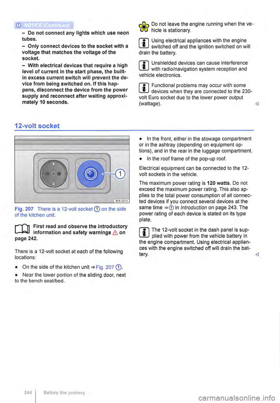
Fig. 207 There is a 12-volt socket CD on the side of the kitchen unit.
l"'"'l'l1 First read and observe the Introductory L-lc.U information and safety warnings & on page 242.
There is a 12-voit socket at each of the following locations:
• On the side of the kitchen unit '*Fig. 207 (D.
• Near the lower portion of the sliding door, next to the bench seaVbed.
2441 Before the journey
Do not leave the engine running when the ve-f!JS hide is stationary.
m Using electrical appliances with the engine W switched off and the ignition switched on will drain the battery.
m Unshielded devices can cause interference W with radio/navigation system reception and vehicle electronics.
m Functional problems may occur with some W devices when they are connected to the 230-volt Euro socket due to the lower power output (wattage).
• In the front, either in the stowage compartment or in the ashtray (depending on equipment op-tions), and in the rear in the luggage compartment.
• In the roof frame of the pop-up roof.
Electrical equipment can be connected to the 12-volt sockets in the vehicle.
The maximum power rating is 120 watts. Do not exceed the maximum power rating. This also ap-plies to the total power consumption of all connec-ted devices if you connect several devices at the same time *
Page 246 of 486
Inserting the Euro plug
• Plug the Euro plug into the Euro socket. The child safety function will disengage at the same time. Electricity will not flow until the child lock has been unlocked.
• Push the Euro plug all the way into the Euro socket so that it is firmly in place and will not fall out as a result of vibration or other vehicle motion.
LEDs above the socket
Constant green light The child lock is disen-gaged. The Euro socket is ready for use.
Flashing red light A fault has occurred. for example cut-off due to excess current or tem-perature.
Compatible devices
Electrical devices with a Euro plug can be connec-ted to the 230-volt Euro socket in the side trim pan-el behind the left front seat.
230-volt grounded safety socket
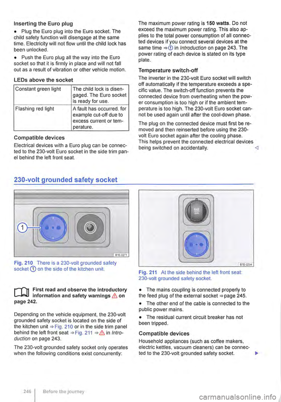
Fig. 210 There is a 230-volt grounded safety socket Q) on the side of the kitchen unit.
r--T'n First read and observe the Introductory L-k.U information and safety warnings & on page 242.
Depending on the vehicle equipment, the 230-volt grounded safety socket is located on the side of the kitchen unit 210 or in the side trim panel behind the left front seat 211 Intro-duction on page 243.
The 230-volt grounded safety socket only operates when the following conditions exist concurrently:
246 I Before the journey
The maximum power rating is 150 watts. Do not exceed the maximum power rating. This also ap-plies to the total power consumption of all connec-ted devices if you connect several devices at the same time in Introduction on page 243. The power rating of each device is stated on its type plate.
Temperature switch-off
The inverter in the 230-volt Euro socket will switch off automatically if the temperature exceeds a spe-cific value. The switch-off function prevents the connected device from overheating when the pow-er consumption is too high or if the ambient tem-perature is too high. The 230-volt Euro socket can-not be used again until after the cool-down phase.
The plug on the connected device must first be re-moved and then reinserted before using the 230-volt Euro socket again after the cooling phase. This helps prevent the connected electrical devices being switched on accidentally. <1
B7E.Q29.4
Fig. 211 At the side behind the left front seat: 230-volt grounded safety socket.
• The mains coupling is connected properly to the feed plug of the external socket 245.
• The other end of the cable is connected to the public power mains.
• The residual current circuit breaker has not been tripped.
Compatible devices
Household appliances (such as coffee makers, electric kettles, vacuum cleaners) can be connec-ted to the 230-volt grounded safety socket. .,.