2020 PEUGEOT PARTNER TEPEE change wheel
[x] Cancel search: change wheelPage 8 of 216

6
Limit the causes of excess
consumption
Spread loads throughout the vehicle; place
the heaviest items in the bottom of the boot,
as close as possible to the rear seats.
Limit the loads carried in the vehicle and
reduce wind resistance (roof bars, roof rack,
bicycle carrier, trailer, etc.). Preferably, use a
roof box.
Remove roof bars and the roof rack after use.
At the end of winter, remove snow tyres and
refit your summer tyres.
Observe the recommendations
on maintenance
Check the tyre pressures regularly, when cold,
referring to the label in the door aperture,
driver's side.
Carry out this check in particular:
-
b
efore a long journey,
-
a
t each change of season,
-
a
fter a long period out of use.
Do not forget the spare wheel and the tyres on
any trailer or caravan. Have your vehicle ser viced regularly (engine
oil, oil filter, air filter, passenger compartment
filter, etc.) and obser ve the schedule of
operations in the manufacturer's service
schedule.
When filling the tank, do not continue after the
3
rd cut-off of the nozzle to avoid over flow.
At the wheel of your new vehicle, it is only
after the first 1,900
miles (3,000 kilometres)
that you will see the fuel consumption settle
down to a consistent average. With a BlueHDi Diesel engine, if the SCR
system is faulty, your vehicle becomes
polluting. Visit a PEUGEOT dealer or a
qualified workshop as soon as possible to
bring your vehicle’s nitrogen oxide emissions
back in line with the regulations.
Eco-driving
Page 107 of 216

105
Electronic engine
immobiliser
All of the keys contain an electronic immobiliser
device.
This device locks the engine supply system.
It is activated automatically when the key is
removed from the ignition.
When the ignition switch is turned on, a
dialogue is set up between the key and the
electronic immobiliser.
The metal part of the key must be correctly
unfolded to ensure a good connection.
In case of lost keys
See a PEUGEOT dealer with the vehicle
registration certificate and your ID.
A PEUGEOT dealer can retrieve the key
code and the transponder code to order the
replacement key.
When you leave the vehicle, check that the
lamps are off and do not leave valuables
visible.
As a safety precaution (with children on
board), remove the key from the ignition when
leaving the vehicle, even for a short time.
Parking brake
Application
F Pull the parking brake lever up to immobilise your vehicle.
F
C
heck that the parking brake is applied
firmly before leaving the vehicle.
When parking on a slope, turn your
wheels towards the kerb and pull the
parking brake lever up.
There is no advantage in engaging a gear
after parking the vehicle, particularly if the
vehicle is loaded. Apply the parking brake only when the
vehicle is stationary
.
In the exceptional case of use of the
parking brake when the vehicle is moving,
apply the brake by pulling gently to avoid
locking the rear wheels (risk of skidding).
Release
F Pull the lever up slightly and press the button to release the parking brake lever.
When the vehicle is being driven, this
warning lamp coming on indicates
that the parking brake is still on or
has not been fully released.
Manual gearbox
To change gear easily, always press the clutch
pedal fully.
To prevent the mat from becoming caught
under the pedal:
-
e
nsure that the mat is positioned and
secured to the floor correctly,
-
n
ever fit one mat on top of another.
When driving, avoid leaving your hand on the
gear knob as the force exerted, even if slight,
may wear the internal components of the
gearbox over time.
6
Driving
Page 115 of 216

113
Operating fault
The flashing and then fixed
illumination of this under-inflation
warning lamp accompanied by the
illumination of the Ser vice warning
lamp, and depending on equipment,
the display of a message indicates a
fault with the system.
In this case, the pressure in the tyres is no
longer monitored.
This alert is also displayed when one or
more wheels are not fitted with a sensor
(for example, a space-saver or steel spare
wheel).
Go to a PEUGEOT dealer or a qualified
workshop to have the system checked or,
following the repair of a puncture, to have the
original wheel, equipped with a sensor, refitted.
Tyre under-inflation
detection with
reinitialisation
The system monitors the pressure in all four
tyres, as soon as the vehicle is moving.
It compares the information given by the
wheel speed sensors with reference values,
which must be reinitialised after ever y tyre
pressure adjustment or wheel change .
The system triggers an alert once a drop in
pressure is detected in one or more tyres.
The under-inflation detection system does
not replace the need for vigilance on the
part of the driver.
This system does not eliminate the need
to check the tyre inflation pressures
(including the spare) every month and
before a long journey.
Driving with under-inflated tyres impairs
handling, extends braking distances and
causes early tyre wear, particularly in
adverse conditions (heavy loads, high
speeds, long journeys).
Driving with under-inflated tyres increases
fuel consumption.
System which automatically checks the
pressures of the tyres while driving. The inflation pressures specified for your
vehicle can be found on the tyre pressure
label.
For more information on the
Identification markings
, refer to the
corresponding section.
Tyre pressures must be checked "cold"
(vehicle stopped for 1
hour or after a
journey of less than 6
miles (10 km)
travelled at a moderate speed).
Other wise (when hot), add 0.3
bar to the
pressures shown on the label.
Under-inflation alert
This is indicated by continuous
illumination of this warning lamp, an
audible signal and, depending on
the equipment installed, a message
displayed on the screen.
F
R
educe speed immediately, avoid excessive
steering movements and sudden braking.
F
S
top the vehicle as soon as it is safe to do
so.
6
Driving
Page 136 of 216

134
F Open the protective covers.
F U nscrew the 4 screws using the spanner
and remove them.
F
T
urn the bars by 90°, positioning the hollow
parts towards the front.
F
R
efit the 4 screws and tighten them using
the spanner.
F
C
lose the protective covers.
Maximum weights on bars
F Only use the strap passages A to secure the load correctly. In all cases, the load must rest on the non-slip
bands provided for this purpose, and must not
touch the roof or the glazing on the roof.
-
T
ransverse bars on longitudinal bars: 75 kg
(these bars are not compatible with the
Zenith).
-
R
oof rack: 120 kg.
-
T
ransverse bars on roof: 100 kg.
-
T
ransverse bars on longitudinal bars: 75
kg.
Other accessories
These accessories and parts, having been
tested and approved for reliability and safety,
are all adapted to your vehicle. A wide range of
genuine parts is available.
Another range of accessories is also available
which is centred around comfort, leisure and
maintenance:
Anti-intrusion alarm, glass engraving, first aid
kit, safety vest, front and rear parking sensors,
hazard warning triangle, alloy wheel anti-theft
bolts, etc.
Seat covers compatible with airbags for front
seat, bench seat, rubber mats, carpet mats,
snow chains, blinds, tailgate bicycle carrier, etc.
To avoid any jamming under the pedals:
-
e
nsure that the mat and its fixings are
positioned correctly,
-
n
ever fit one mat on top of another.
Recommendations for
loading the roof
This procedure requires the use of the spanner
supplied with the tools for changing a wheel.For more information on Changing a
wheel , refer to the corresponding section.
Audio systems, hands-free kit, speakers, CD
changer, navigation, USB Box, Video Kit, etc.
With a wide range of audio and telematic
equipment offered on the market, the technical
constraints associated with the installation of
devices from these product families require
Practical information
Page 145 of 216

143
Temporary puncture
repair kit
The kit is located in a storage compartment
under the front seat.
Vehicles supplied with a temporary puncture
repair kit do not have a spare wheel or the
corresponding tools ( jack, wheelbrace, etc.).
The temporary puncture repair kit comprises a
compressor and a bottle of sealant.
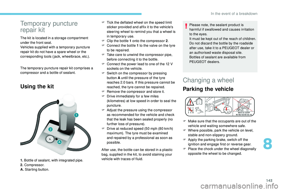
Using the kit
1. Bottle of sealant, with integrated pipe.
2. Compressor.
A. Starting button. F
T
ick the deflated wheel on the speed limit
sticker provided and affix it to the vehicle's
steering wheel to remind you that a wheel is
in temporary use.
F
C
lip the bottle 1 onto the compressor 2
.
F
C
onnect the bottle 1 to the valve on the tyre
to be repaired.
F
T
ake care to unwind the compressor pipe,
before connecting it to the bottle.
F
C
onnect the power lead to one of the 12 V
sockets on the vehicle.
F
S
witch on the compressor by pressing
button A until the pressure of the tyre
reaches 2.0 bars. If this pressure cannot be
reached, the tyre cannot be repaired.
F
R
emove the compressor and store it.
F
D
rive immediately for a few miles
(kilometres) at low speed in order to seal the
puncture.
F
A
djust the pressure using the compressor
as recommended for the vehicle and check
that the leak has been sealed properly (no
further loss of pressure).
F
D
rive at reduced speed (50 mph (80 km/h)
maximum). The tyre must be examined
and repaired by a professional as soon as
possible.
After use, the bottle can be stored in a plastic
bag, supplied in the kit, to avoid staining your
vehicle with traces of fluid. Please note, the sealant product is
harmful if swallowed and causes irritation
to the eyes.
It must be kept out of the reach of children.
Do not discard the bottle by the roadside
after use, take it to a PEUGEOT dealer or
an authorised waste disposal site.
Bottles of sealant are available from
PEUGEOT dealers.
Changing a wheel
Parking the vehicle
F Make sure that the occupants are out of the
vehicle and waiting somewhere safe.
F
W
here possible, park the vehicle on level,
stable and non-slippery ground.
F
A
pply the parking brake, switch off the
ignition and engage first or reverse gear.
F
P
lace the chock under the wheel diagonally
opposite the wheel to be changed.
8
In the event of a breakdown
Page 147 of 216

145
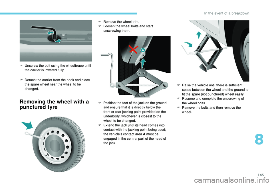
F Detach the carrier from the hook and place the spare wheel near the wheel to be
changed.
Removing the wheel with a
punctured tyre
F Unscrew the bolt using the wheelbrace until the carrier is lowered fully. F
R
emove the wheel trim.
F
L
oosen the wheel bolts and start
unscrewing them.
F
P
osition the foot of the jack on the ground
and ensure that it is directly below the
front or rear jacking point provided on the
underbody, whichever is closest to the
wheel to be changed.
F
E
xtend the jack until its head comes into
contact with the jacking point being used;
the vehicle's contact area A must be
engaged in the central part of the head of
the jack. F
Ra
ise the vehicle until there is sufficient
space between the wheel and the ground to
fit the spare (not punctured) wheel easily.
F
R
esume and complete the unscrewing of
the wheel bolts.
F
R
emove the bolts and then remove the
wheel.
8
In the event of a breakdown
Page 148 of 216

146
Fitting the spare wheel
When using a non-uniform spare wheel,
do not exceed 50 mph (80 km/h).
The spare wheel is not designed to
be used over long distances. Have
the tightening of the bolts and the tyre
pressure of the spare wheel checked by a
PEUGEOT dealer or a qualified workshop
as soon as possible.
Also, have the original wheel repaired
and refitted by a PEUGEOT dealer or a
qualified workshop as soon as possible.
F
P
osition the wheel on the hub and start
tightening the bolts by hand.
Ensure that the jack is stable. The foot
of the jack must be in contact with the
ground and directly below the jacking
point used.
If the ground is slippery or loose, the jack
may slip or drop – Risk of injury!
Ensure that the jack is positioned only at
one of jacking points under the vehicle,
making sure that the vehicle's contact
sur face is centred on the head of the jack.
Other wise, there is a risk of damage to the
vehicle and/or of the jack collapsing – Risk
of injury!
Do not extend the jack until you have
started unscrewing the bolts on the wheel
to be changed and have placed the chock
under the wheel diagonally opposite.
F
C
arry out an initial tightening of the bolts
using the wheelbrace.
F
L
ower the vehicle completely by folding the
jack, then remove the jack.
F
T
ighten the wheel bolts again using the
wheelbrace; tighten them fully without
forcing them.
F
P
lace the wheel to be repaired in the carrier.
In the event of a breakdown
Page 154 of 216

152
Rear lamps
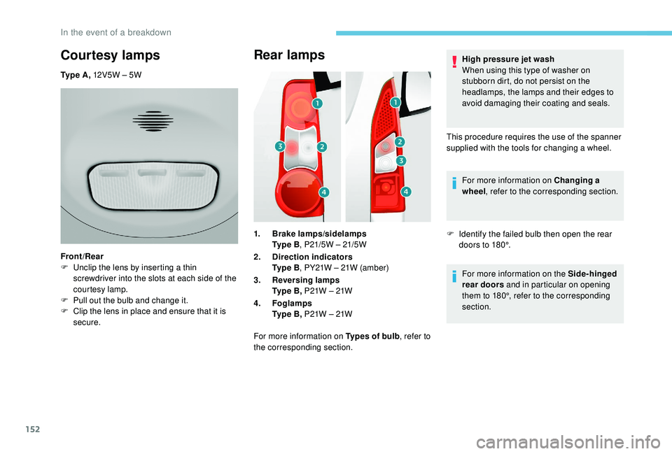
1.Brake lamps/sidelamps
Ty p e B , P21/5W – 21/5W
2. Direction indicators
Ty p e B , PY21W – 21W (amber)
3. Reversing lamps
Ty p e B , P21W – 21W
4. Foglamps
Ty p e B , P21W – 21W
For more information on Types of bulb , refer to
the corresponding section. High pressure jet wash
When using this type of washer on
stubborn dirt, do not persist on the
headlamps, the lamps and their edges to
avoid damaging their coating and seals.
This procedure requires the use of the spanner
supplied with the tools for changing a wheel. For more information on Changing a
wheel , refer to the corresponding section.
F I dentify the failed bulb then open the rear
doors to 180°.
For more information on the Side-hinged
rear doors and in particular on opening
them to 180°, refer to the corresponding
section.
Courtesy lamps
Ty p e A , 12V5W – 5W
Front/Rear
F
U
nclip the lens by inserting a thin
screwdriver into the slots at each side of the
courtesy lamp.
F
P
ull out the bulb and change it.
F
C
lip the lens in place and ensure that it is
secure.
In the event of a breakdown