Page 134 of 216
132
Instructions for fitting and before
each use
Check that the swan neck is correctly locked by
verifying the following points:
-
t
he green mark on the locking wheel is
visible.
-
t
he safety lock on the locking wheel is
facing rearward.
-
t
he safety lock is closed and the key
removed; the locking wheel can no longer
be operated,
-
t
he swan neck must no longer move in its
c a r r i e r.
When hooking up the towbar, do not forget to
connect the electrical wiring harness.
Fitting
During use
Never unlock the device when a trailer or
load carrier is fitted to the swan neck.
After use
For journeys made without a trailer or load
carrier, the swan neck must be removed
and the blanking plug inserted in the
carrier. This measure applies particularly if
the swan neck could hinder visibility of the
number plate or lighting.
Removal
Practical information
Page 136 of 216

134
F Open the protective covers.
F U nscrew the 4 screws using the spanner
and remove them.
F
T
urn the bars by 90°, positioning the hollow
parts towards the front.
F
R
efit the 4 screws and tighten them using
the spanner.
F
C
lose the protective covers.
Maximum weights on bars
F Only use the strap passages A to secure the load correctly. In all cases, the load must rest on the non-slip
bands provided for this purpose, and must not
touch the roof or the glazing on the roof.
-
T
ransverse bars on longitudinal bars: 75 kg
(these bars are not compatible with the
Zenith).
-
R
oof rack: 120 kg.
-
T
ransverse bars on roof: 100 kg.
-
T
ransverse bars on longitudinal bars: 75
kg.
Other accessories
These accessories and parts, having been
tested and approved for reliability and safety,
are all adapted to your vehicle. A wide range of
genuine parts is available.
Another range of accessories is also available
which is centred around comfort, leisure and
maintenance:
Anti-intrusion alarm, glass engraving, first aid
kit, safety vest, front and rear parking sensors,
hazard warning triangle, alloy wheel anti-theft
bolts, etc.
Seat covers compatible with airbags for front
seat, bench seat, rubber mats, carpet mats,
snow chains, blinds, tailgate bicycle carrier, etc.
To avoid any jamming under the pedals:
-
e
nsure that the mat and its fixings are
positioned correctly,
-
n
ever fit one mat on top of another.
Recommendations for
loading the roof
This procedure requires the use of the spanner
supplied with the tools for changing a wheel.For more information on Changing a
wheel , refer to the corresponding section.
Audio systems, hands-free kit, speakers, CD
changer, navigation, USB Box, Video Kit, etc.
With a wide range of audio and telematic
equipment offered on the market, the technical
constraints associated with the installation of
devices from these product families require
Practical information
Page 145 of 216

143
Temporary puncture
repair kit
The kit is located in a storage compartment
under the front seat.
Vehicles supplied with a temporary puncture
repair kit do not have a spare wheel or the
corresponding tools ( jack, wheelbrace, etc.).
The temporary puncture repair kit comprises a
compressor and a bottle of sealant.
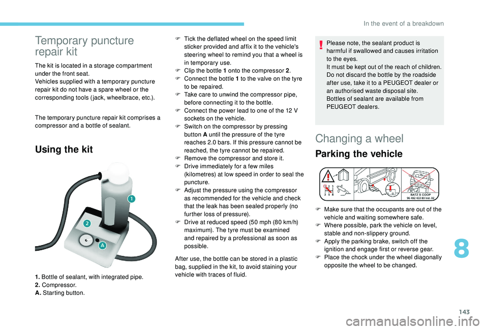
Using the kit
1. Bottle of sealant, with integrated pipe.
2. Compressor.
A. Starting button. F
T
ick the deflated wheel on the speed limit
sticker provided and affix it to the vehicle's
steering wheel to remind you that a wheel is
in temporary use.
F
C
lip the bottle 1 onto the compressor 2
.
F
C
onnect the bottle 1 to the valve on the tyre
to be repaired.
F
T
ake care to unwind the compressor pipe,
before connecting it to the bottle.
F
C
onnect the power lead to one of the 12 V
sockets on the vehicle.
F
S
witch on the compressor by pressing
button A until the pressure of the tyre
reaches 2.0 bars. If this pressure cannot be
reached, the tyre cannot be repaired.
F
R
emove the compressor and store it.
F
D
rive immediately for a few miles
(kilometres) at low speed in order to seal the
puncture.
F
A
djust the pressure using the compressor
as recommended for the vehicle and check
that the leak has been sealed properly (no
further loss of pressure).
F
D
rive at reduced speed (50 mph (80 km/h)
maximum). The tyre must be examined
and repaired by a professional as soon as
possible.
After use, the bottle can be stored in a plastic
bag, supplied in the kit, to avoid staining your
vehicle with traces of fluid. Please note, the sealant product is
harmful if swallowed and causes irritation
to the eyes.
It must be kept out of the reach of children.
Do not discard the bottle by the roadside
after use, take it to a PEUGEOT dealer or
an authorised waste disposal site.
Bottles of sealant are available from
PEUGEOT dealers.
Changing a wheel
Parking the vehicle
F Make sure that the occupants are out of the
vehicle and waiting somewhere safe.
F
W
here possible, park the vehicle on level,
stable and non-slippery ground.
F
A
pply the parking brake, switch off the
ignition and engage first or reverse gear.
F
P
lace the chock under the wheel diagonally
opposite the wheel to be changed.
8
In the event of a breakdown
Page 146 of 216

144
If the vehicle is equipped with a towbar, it is
sometimes necessary to raise the vehicle
slightly to make it easier to remove the spare
wheel from its carrier.
In certain ground conditions and/or when
transporting heavy loads, consult with a
PEUGEOT dealer or a qualified workshop.
The jack and the tool kit are specific to your
vehicle. Do not use them for any other purpose.
Access to tools
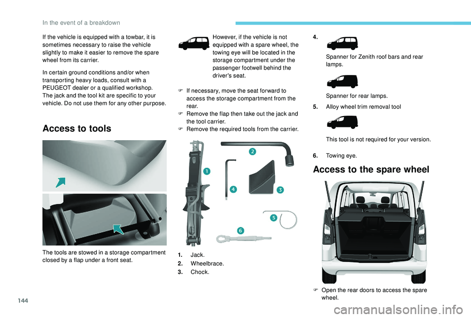
4.Spanner for Zenith roof bars and rear
lamps.
Spanner for rear lamps.
5. Alloy wheel trim removal tool
This tool is not required for your version.
6. Towing eye.
Access to the spare wheel
F Open the rear doors to access the spare
wheel.
The tools are stowed in a storage compartment
closed by a flap under a front seat. However, if the vehicle is not
equipped with a spare wheel, the
towing eye will be located in the
storage compartment under the
passenger footwell behind the
driver's seat.
F
I
f necessary, move the seat for ward to
access the storage compartment from the
r e a r.
F
R
emove the flap then take out the jack and
the tool carrier.
F
R
emove the required tools from the carrier.
1. Jack.
2. Wheelbrace.
3. Chock.
In the event of a breakdown
Page 147 of 216
145
F Detach the carrier from the hook and place the spare wheel near the wheel to be
changed.
Removing the wheel with a
punctured tyre
F Unscrew the bolt using the wheelbrace until the carrier is lowered fully. F
R
emove the wheel trim.
F
L
oosen the wheel bolts and start
unscrewing them.
F
P
osition the foot of the jack on the ground
and ensure that it is directly below the
front or rear jacking point provided on the
underbody, whichever is closest to the
wheel to be changed.
F
E
xtend the jack until its head comes into
contact with the jacking point being used;
the vehicle's contact area A must be
engaged in the central part of the head of
the jack. F
Ra
ise the vehicle until there is sufficient
space between the wheel and the ground to
fit the spare (not punctured) wheel easily.
F
R
esume and complete the unscrewing of
the wheel bolts.
F
R
emove the bolts and then remove the
wheel.
8
In the event of a breakdown
Page 148 of 216

146
Fitting the spare wheel
When using a non-uniform spare wheel,
do not exceed 50 mph (80 km/h).
The spare wheel is not designed to
be used over long distances. Have
the tightening of the bolts and the tyre
pressure of the spare wheel checked by a
PEUGEOT dealer or a qualified workshop
as soon as possible.
Also, have the original wheel repaired
and refitted by a PEUGEOT dealer or a
qualified workshop as soon as possible.
F
P
osition the wheel on the hub and start
tightening the bolts by hand.
Ensure that the jack is stable. The foot
of the jack must be in contact with the
ground and directly below the jacking
point used.
If the ground is slippery or loose, the jack
may slip or drop – Risk of injury!
Ensure that the jack is positioned only at
one of jacking points under the vehicle,
making sure that the vehicle's contact
sur face is centred on the head of the jack.
Other wise, there is a risk of damage to the
vehicle and/or of the jack collapsing – Risk
of injury!
Do not extend the jack until you have
started unscrewing the bolts on the wheel
to be changed and have placed the chock
under the wheel diagonally opposite.
F
C
arry out an initial tightening of the bolts
using the wheelbrace.
F
L
ower the vehicle completely by folding the
jack, then remove the jack.
F
T
ighten the wheel bolts again using the
wheelbrace; tighten them fully without
forcing them.
F
P
lace the wheel to be repaired in the carrier.
In the event of a breakdown
Page 149 of 216

147
Never go underneath a vehicle that is
supported only by a jack (use an axle stand).
Never use an electric screwdriver instead of
the wheelbrace.
Refitting the repaired wheel
The wheel is refitted in the same way as the
spare wheel; do not forget to refit the wheel
trim.For more information on Identification
markings
, including the tyre label, refer to
the corresponding section.
For more information on Tyre under-
inflation detection , including
recommendations after changing a wheel
with a tyre under-inflation detection
sensor, refer to the corresponding section.
F
S
ecure the carrier on the hook, then raise
the carrier by tightening the bolt with the
wheelbrace.
F
T
ighten the bolt fully and check that the
wheel is held flat against the floor.
If not, repeat the procedure.
Fitting the wheel trim on
the rim
The valve of the wheel must be centred against
the notch on the wheel trim.
This position is essential to fit the wheel trim
properly on the metal rim. (In case of incorrect
positioning of the valve in line with the notch,
the anti-rotation system will be in contact with
the bolt heads and may be damaged if the user
persists in fitting the wheel trim in this incorrect
position.)
- Make sure that the wheel trim's outer edge is not pressed against the rim or lowered into it:
Correct wheel trim edge position.
8
In the event of a breakdown
Page 150 of 216
148
Check the position of the wheel valve
in relation to the ring of the wheel trim.
Incorrect
wheel trim edge position.
-
B
e sure to pre-clip all fixing tabs except the
last (opposite the valve cut-out). -
B
riskly hit with the palm of the hand the tab
opposite the valve (at the location of the last
fixing tab, always in the clipping direction). Incorrect
valve position: below the ring.
Distortion of the edge of the wheel trim at the
valve, due to incorrect fitting.
In the event of a breakdown