Page 297 of 443

Electric rear window defogger switch 5-216 Features and controls
5
When the front wipers have frozen to the windshield at the parked
positions, turning on
this switch will heat the windshield to make the wipers operable. Press the electric rear window defogger switch and the deicer willoperate.
N00523701530
The rear window defogger can be used when the engine is running. The indicator light (A) will come on whenyou press the electric rear window defogger switch. Electric current will flow through the heating wires on the rear window to helpclear away moisture or frost. After approximately 15 to 20 minutes of operation, the system will shut off automati- cally. To switch the defogger OFF before 15 to 20minutes have passed, pr
ess the switch again.
The indicator light will go out and the defog- ger will turn off.If you need the defogger for more than 15 to 20 minutes, press the switch again. This will add 15 to 20 more minutes.
NOTE
The wiper deicer is
activated/de
activated,
depending on the operation of the rear win-dow defogger. Refer to
“Electric rear win-
dow defogger switch” on page 5-216.
Electric rear window defog- ger switch
CAUTION The rear window defogge
r is not designed to
melt snow. Remove any snow manuallybefore using the rear window defogger. Use the rear window defogger only after the engine has started and
is running. Be sure to
turn the defogger switch off immediately after the window is clea
r to save on battery
power. Do not place stickers
, tape, or other items
that are attached with
adhesive over the grid
wires on the rear window. When cleaning the insi
de rear window, use a
soft cloth and wipe
lightly over the grid
wires.NOTE
If your vehicle is equi
pped with heated out-
side rearview mirror
, mist can also be
removed from the outsi
de rearview mirrors
when the rear window
defogger switch is
pressed. (Refer to “H
eated outside rearview
mirror” on page 5-65.) On vehicles equipped wi
th the wiper deicer,
when the rear window
defogger switch is
pushed, the windshiel
d becomes warm and
the wipers become operable. (Refer to “Wiper deicer switc
h” on page 5-215.)
BK0278200US.book 216 ページ 2019年4月10日 水曜日 午前10時59分
Page 298 of 443

Heated steering wheel switch (if so equipped)
Features and controls 5-217
5
N00589100058
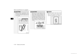
The heated steering wheel contains internal heaters in the rim. Heating areas are shown in the illustration.
: Heating area
The heated steering wheel can be operated when the ignition switch or operation mode is in ON.
To turn on the heated steering wheel, push the heated steering wheel switch. The heatedsteering wheel will ope
rate for approximately
30 minutes and then it
will automatically turn
off.The indicator light (A) will illuminate while the heated steering wheel is operating.
It is possible to cha
nge the setting to make
the rear window defogger operate automati-cally when ambient temperature becomeslow while the engine is running, even if you do not push the rear window defogger switch.It operates automati
cally only once after
turning the ignition sw
itch to the “ON” posi-
tion or putting the ope
ration mode in ON.
If you choose this setting, the heated outside rearview mirror (if so
equipped) and wiper
deicer (if so equippe
d) will also operate
automatically at the same time. For further informati
on, please contact your
authorized Mitsubish
i Motors dealer.
On vehicles equipped with the Smartphone- link Display Audio (SDA), screen operations can be used to make the adjustment.Refer to the separate owner’s manual for details.NOTE
Heated steering wheel switch
(if so equipped)
WA R N I N G Persons who are unable to feel tempera- ture change or skin
pain due to age, ill-
ness, injury, medicati
on, fatigue or other
physical conditions or who have sensitive skin may suffer burns when using theheated steering wheel. To reduce the risk of burns, people with such conditions must use care when using the heated steeringwheel.
BK0278200US.book 217 ページ 2019年4月10日 水曜日 午前10時59分
Page 299 of 443

Horn switch 5-218 Features and controls
5
N00523801195
To honk the horn, press around the “ ” mark on the steering wheel.
N00563701183
The Link System takes control of the devices connected via the USB i
nput terminal or the
Bluetooth
® device; the system allows the
connected device to be operated by using the switches in the vehicl
e or voice commands.
For details on how to operate, refer to “USBinput terminal” on page 5-218 and the sepa- rate owner’s manual. Bluetooth
® is a registered trademark of
BLUETOOTH SIG, INC.
N00566701256
You can connect your USB memory device or iPod
* to play music files stored in the USB
memory device or iPod. * : “iPod” is a register
ed trademark of Apple
Inc. in the United Stat
es and other countries.
This section explains how to connect and remove a USB memory device or iPod. Refer to the separate owner’s manual for details on the types of
connectable devices
and supported files, and how to play musicfiles. The USB input terminal
(A) is located in the
illustrated positions.
CAUTION If water or any other li
quid is spilled on the
steering wheel, allow it to dry thoroughlybefore attempting to us
e the heated steering
wheel. Turn the heated steering wheel off immediately if it appe
ars to be malfunction-
ing during use. Also be aware that us
ing the heated steering
wheel with the engine
off may run the bat-
tery down.
Horn switch
Link System
USB input terminal USB input terminal locations Instrument panel
BK0278200US.book 218 ページ 2019年4月10日 水曜日 午前10時59分
Page 300 of 443

USB input terminal
Features and controls 5-219
5
N00566801215
1. Park your vehicle in a safe place and turn the ignition switch to the “LOCK” posi-tion or put the operation mode in OFF. 2. Open the USB input terminal cover.
3. Connect a commercia
lly available USB
connector cable (A) to the USB memorydevice (B). 4. Connect the USB connector cable to the USB input terminal. 5. To remove the USB connector cable, turn the ignition switch to the “LOCK” posi- tion or put the operation mode in OFFfirst and perform the installation steps in reverse.
CAUTION Keep the lid of the floor console box closed while driving the vehicle. A lid or the con-tents of the floor console box could other- wise cause injuries. NOTE
When closing the floor
console box, be care-
ful not to trap the USB connector cable.Floor console box (if so equipped)
How to connect a USB memory device Back of floor console box (if so equipped)
NOTE
Do not connect the USB memory device to the USB input term
inal directly.
The USB memory devi
ce may be damaged.
BK0278200US.book 219 ページ 2019年4月10日 水曜日 午前10時59分
Page 301 of 443

Sun visors 5-220 Features and controls
5
N00566901245
1. Park your vehicle in a safe place and turn the ignition switch to the “LOCK” posi-tion or put the operation mode in OFF. 2. Open the USB input terminal cover. 3. Connect the connector cable to the iPod. 4. Connect the connector cable to the USB input terminal. 5. To remove the connector cable, turn theignition switch to th
e “LOCK” position or
put the operation mode in OFF first and perform the installation steps in reverse.
N00524601451
Pull the sun visor downward (1) to reduce front glare while driving. To reduce side glare, turn the visor to the side (2).
A vanity mirror is fitted to the back of the sun visor. Operating the lid of the vanity mirror will automatically turn on the mirror light (A).
How to connect an iPod
NOTE
Use a genuine connec
tor cable from Apple
Inc.
Sun visors
Vanity mirror
CAUTION If the lid of vanity mirror with light is kept open for prolonged periods
of time, the vehi-
cle’s battery will be discharged.
BK0278200US.book 220 ページ 2019年4月10日 水曜日 午前10時59分
Page 302 of 443

12 V power outlets
Features and controls 5-221
5
The holder (B) is located on the back of the sun visor.
N00525001784
To use a “plug-in” type accessory, open thecover or remove the cap, and insert the plugin the power outlet.
Accessories can be operated when the igni- tion switch or the operation mode is in ON or ACC.
Ticket holder
CAUTION Do not leave plastic cards in the ticket holder. Because the inside of the vehicle will become hot if the vehicle is parked in strong sunlight, the cards could deform or crack.
12 V power outlets
CAUTION Be sure to use a “plug-in” type accessory operating at 12 V and at 120 W or less.When using more than one socket at the same time, make sure
the total power con-
sumption of the electrical accessories doesnot exceed 120 W at 12 V. Also be aware that
using electronic equip-
ment with the engine
off may run the battery
down. When the power outlet is not in use, be sure to close the power outle
t cover or replace the
cap. This will prevent the power outlet frombecoming clogged and short circuiting.NOTE
Three 12V power
outlets can be used simul-
taneously.
Type 1 Instrument panel
BK0278200US.book 221 ページ 2019年4月10日 水曜日 午前10時59分
Page 303 of 443

USB port (for chargi
ng) (if so equipped)
5-222 Features and controls
5
Accessories can be operated in all ignition switch positions or all operation modes.
N00596400024
The USB port (for charging) can be used as a power source of the USB appliances when the ignition switch or th
e operation mode is in
ON or ACC. There are two USB ports (for charging) located on the back of the floor console box.When using the USB port (for charging), open the lid and conne
ct the USB connector
cable to it.
Ty p e 2 Floor console box (if so equipped)Rear
USB port (for charging)
(if so
equipped)
CAUTION When the USB port (for charging) is not in use, be sure to close
the lid, because the USB
port (for charging) might be short-circuitedby clogging foreign mate
rials and the con-
nected devices and the USB port (for charg- ing) might be damaged.
Insert the USB connect
or cable in the USB
port (for charging) firmly.If the USB connector cable does not insert init firmly, it may beco
me extremely hot and
the fuses may blow. Be sure that the power consumption does not exceed 10.5 W {The peak outlet current or voltage of the USB port (for charging) is DC5 V-2.1 A}. The connected devices or the USB port (for charging) may be damaged. Do not use the reversible USB connector cable that the USB
connector board is
located in the centre. The USB port (for charging) might be dam- aged. Long use of the electr
ic appliance without
running the engine may run down the bat-tery.NOTE
The USB ports (for charging) can be used only as a power source
. These are not con-
nected to the audio de
vices of the vehicles.
Do not charge many mobile devices together by using a multi-plug adapter of the USB port (for charging). If water or spill beve
rages has splashed on
the USB ports (for charging), stop using it and have the vehicle
checked by an autho-
rized Mitsubishi Motors dealer.CAUTION
BK0278200US.book 222 ページ 2019年4月10日 水曜日 午前10時59分
Page 304 of 443

HomeLink® Wireless Control System (if so equipped)
Features and controls 5-223
5
N00554301040
HomeLink
® Wireless Control System is a
registered trademark of Gentex Corporation. HomeLink
® provides a convenient way to
replace up to 3 hand-held radio-frequency (RF) transmitters used
to activate devices
such as gate operators, garage door openers, entry door locks, securi
ty systems, even home
lighting. Addi
tional HomeLink
® information
can be found at www.homelink.com, www.youtube.com/HomeL
inkGentex, or by
calling the toll-free HomeLink
®-Hotline at 1-
800-355-3515.
N00584600029
Some garage door openers manufactured after 1995 have “rollin
g code protection”.
To program a garage door openerequipped with “rolli
ng code protection”;
you will need to access the garage door opener motor to press the motor’s “Learn”or “Smart” buttons. For convenience, use a ladder and another person to assist you. It is recommended that a new battery be placed in the hand-held transmitter of the device being programmed to HomeLink
®
for quicker training and accurate trans- mission of the radio-frequency signal.
HomeLink
® Wireless Con-
trol System
(if so equipped)
WA R N I N G Do not use HomeLink
® with any garage
door opener that lacks safety stop and reverse features as re
quired by U.S. Fed-
eral Regulations.
A garage door opener
which cannot detect an object in the path of a closing garage d
oor and then auto-
matically stop and reverse, does not meetcurrent U.S. Federal Regulations. Using a garage door opener wi
thout these features
increases the risk of serious injury ordeath.
During programming, your garage door or gate may open or cl
ose. Make sure that
people and ob
jects are clear of the garage
door or gate that you are programming.NOTE
Once HomeLink
® is programmed, retain the
original transmitter for future programming procedures (for exam
ple, new vehicle pur-
chases). Upon sale of the vehicle, the pro- grammed HomeLink
® buttons should be
erased for security purposes. Refer to “Cleaning the programmed information” on page 5-227. You can program a maximum of 3 devices. To change or replace any of the 3 devicesafter it has been in
itially programmed, you
must first erase the current settings. See “Cleaning the programmed information”on page 5-227 or “Reprogramming a single HomeLink
® button” on page 5-227.
WA R N I N G
1-
HomeLink
® button 1
2-
HomeLink
® button 2
3-
HomeLink
® button 3
Before programming Home- Link
®
BK0278200US.book 223 ページ 2019年4月10日 水曜日 午前10時59分