Page 241 of 316

#
Tighten thew heel bolts or nuts evenlyint he
sequence indicated (1 to6 ).
Specified tightenin gtorque:
R Steel wheel bolts: 177l b-f t(24 0N m)
R Whee lnuts: 133lb-f t(18 0N m)
R Alloywheel bolts: 133lb-f t(18 0N m) #
Push thep isto nont hehydraulic jac kinagain
and close thep ressur erelease scr ew. #
Vehicles with all-wheel drive: turnthe jack
spindle clockwise as farasitw illg o.
% Yo
uc an no winstallth eh ub caps on steel
wheels wit hwheel bolts. The ins tallation pro‐
cedur edepends on whe ther theh ub cap acts
as atrimt hat co vers thew hole wheel, or just
co vers thec enter. #
Wheel with hub cap: positiontheo pening
fo rt he tir evalveint he hub cap overthe tire
va lve. #
Push thee dgeoft he hub cap ont othe wheel
ri mw ithb othh ands until it engages into
place. Mak esuret he hub cap retaining
cat ches engag eonthesteel wheel. #
Wheel with central hub cap: positionthe
re tainin glugs of thec ent ralh ub cap overthe
whee lbolts. #
Hitthem iddle of theh ub cap toengag eiton
th ew heel. #
Secur ethe faulty wheel in thes par ew heel
brac ket. #
Vehicles with Super Single tires: transport
th ef aulty rear wheel on thel oad area. The
re ar wheel is tool arge fort he spar ewheel
brac ket. #
Chec kthe tir epressur eoft he newl yins talled
wheel and adjus titifnecessar y. #
Retighten thew heel bolts or wheel nuts tothe
specified tightening torque af tert he vehicle
has been driven 31miles (50 km). #
When using awhee lors parew hee lwitha
ne worn ewly painted whee lrim, ha vethe
wheel bolt sornutsr etightene dafter appr ox‐
ima tely 620 mile s(1,000 km) to3,10 0m iles
(5,000 km).
% Ve
hicles with thet irep ressur emonitor
sy stem: all ins talled wheels mus tbeequip‐
ped wit hfunctioning sensors.
Mak esuretoo bservethef ollowing fur ther rela‐
te ds ubject:
R Notesont irep ressur e(/pag e217 ) Spar
ewheel Note
sont he eme rgency spar ewheel and
spar ewheel Spar
ewheel: wheel and tir edimension saswell
as thet ype of tir ecorrespond totheo ther ins tal‐
led wheels.
Emer gency spar ewheel: wheel and/or tire
dimension saswell asthet ype of tir earediffer‐
ent from thew heel tobe replaced. Alabel wit ha
speed limit can be found on thee mer gency spa re
wheel.
An ins talled emer gency spa rewheel or spare
wheel changes thed riving characteristic sand
bear srisks. &
WARNING Risk of accident caused by
incor rect wheel and tir edimensions
Whe nthe emergency spar ewheel or the
spar ewheel is ins talled, driving characteris‐
tic sm aybe se verely affected.
The reis an inc reased risk of an accident.
To prev ent hazardous situations: #
Oncet he spar ewheel or thee mer gency
spa rewheel has been ins talled, check
th et irep ressur eand adjus tifneces‐
sar y. #
The emer gency spa rewheel ma yonly
be used temp oraril yand mus tbe
re placed wit hastandar dwheel as soon
as possible. #
Neverins tall mor ethan one emergency
spar ewheel. #
When operating your vehicle wit hthe
emergency spar ewheel ins talled, adapt Wheels and tires
239
Page 242 of 316

yo
ur drivin gstyle acco rdingly and drive
carefully. #
Do no tswitc hoffESP ®
. #
Sno wchains mus tnotbe ins talled on
th ee mer gency spa rewheel. #
Replace thee mer gency spa rewheel
af te ram aximu mofs ixyears, rega rd‐
less of wear. R
When usin ganemergency spa rewheel
(whic hisd iffe re nt from thew heel tobe
re placed) atop speed of 50 mph(80 km/h)
mus tnotbe exc eeded.
R The tir epressur eoft he emergency spare
whee lmustbec heckedb efor estartin gaj our‐
ne y(/pag e221).
R Have thee mer gency spa rewheel replaced by
aq ualified specialis tworks hop. &
WARNING Risk of accident from dam‐
aged spa rewheel wit hSuper Sin glet ires
Ve hicles with Super Single tires
The tir eofthe spar ewheel exposed toabo ve-
ave rage loads af terb eing ins talled on ther ear
axle. If youe xceed them aximum speed or the
maximu mdista nce, or ins tallth es par ew heel
again, thet ireoft he spar ewheel ma ybe
damaged. The tir edamag emaynotbev isible
and no tdetectable.
Ad amaged tir emaycause alossoft irep res‐
sure. Thi scould cause youtol ose control of
th ev ehicle. #
Onlyusethes par ew heel if it has not
ye tb eeni nstalled on ther ear axle with
th ec urrent tires. #
Ifth es par ew heel had been ins talled on
th er ear axle, ha vethet ireoft he spare
wheel replaced af terc hanging the
wheel again, ir respectiv eofthe dis‐
ta nce. #
Fors afet yr easons, when changing atire
ensur ethat only thet irev alvetype
appr ovedfor thet ires is used. *
NO
TEDama getothet ransmission Ve
hicles with Super Single tires: whenyou
ins tallth es par ew heel on ther ear axle, the
transmission ma ybedamaged bythed iffe r‐
ent rotational speed softhe wheels. #
When thes par ew heel is ins talled on
th er ear axle, obser vethem aximum
speed of 34 mph(55 km/h) and the
maximu mdriving dis tance of 62 miles
(100 km). %
It is possible
,without restrictions, touse the
spar ewheel only on thef ront axle of avehi‐
cle wit hSuper Single tires.
The following should be checkedr egular ly,p artic‐
ularly prior tolong journe ys:
R The secur epositioning of thes par ew heel
R The tir epressur eoft he spar ewheel (adjust
th et irep ressur eifn ecessary) (/ page218 )
R Thef astenings of thes par ew heel brac ket
Re place thet ires af ters ixyearsatt he latest,
re ga rdless of wear.T his also applies tothes pare
wheel.
% If
yo uh ave installed an emer gency spa re
wheel or spar ewheel, thet irep ressur emoni‐
to rw illn ot function fort his wheel.T he emer‐
ge ncy spa rewheel or spar ewheel is not
equipped wit hasensor form onitoring tire
pressu re. Installing/removing
thes pare wheel Ve
hicles with rear wheel drive: removing the
spar ewheel (Cargo Van/Passenger Van) Bolt co
vers fort he saf etyh ooks (exa mp le: Cargo
Va n) 240
Wheels and tires
Page 243 of 316

#
Open ther ear-end doors. #
Place ascrew driver int orecesses 2and
th en pr yoffco vers 1 . #
Using thel ug wrenc hfromt hevehicle tool kit,
unscr ewthen ow visible bolts counter-clock‐
wise byappr oximatel y20turns. #
Slightly raise spar ewheel car rier 4 and
unhook left-hand saf etyh ook 3. #
Assemble thep um pleve rfor thej acka nd
slide it int osleeve5 onther ight-ha ndside
of spar ewheel car rier 4. #
Raise spar ewheel car rier 4 withthe pump
le ve ra nd unhook right-han dsafet yh ook 3. #
Slowl ylow er spar ewhee lcarrier 4 tothe
ground. #
Lift spar ewheel car rier 4 slightl yand pull
th ep um pleve rout of thes lee ve. #
Use thep um pleve rtol iftt he spar ewheel
be yond ther ear edg eofsparew heel car rier
4. #
Carefully remo vethes par ew heel from spare
wheel car rier 4.T he spar ewheel is heavy.
When thes par ew heel is remo ved, thec enter
of gr avity changes due totheh eavy weight of
th ew heel. The spar ewheel ma yslip down or
tip ove r.
Ve hicles with rear wheel drive: installin gthe
spar ewheel (Cargo Van/Passenger Van) #
Carefully place thes par ew heel ont ospare
wheel car rier 4.T he spar ewheel is heavy.
When youp lacethe spar ewheel ont ospare
wheel car rier 4,t he center of gravity
ch anges due tothew eight of thew heel. The
spar ewheel ma yslip down or tip over. #
Slide thep um pleve rfor thej acki ntos leeve
5 on spar ewheel car rier 4. #
Raise spar ewheel car rier 4 withthe pump
le ve ra nd attac hright-ha ndsafetyh ook 3. #
Slight lyraise spar ewheel car rier 4 and
attac hleft-hand saf etyh ook 3. #
Pull thep um pleve rout of slee ve5 . #
Using thel ug wrench, tighten saf etyh ook
bolts 3byturning them clockwise. #
Replace and engag ecovers 1. #
Close ther ear-end doors.
Ve hicles with rear wheel drive: removing the
spar ewheel (vehicl ewithl ow ered chassis) Bolt co
vers fort he saf etyh ooks (exa mp le: Cargo
Va n) Wheel
sand tires 241
Page 244 of 316

#
Open ther ear-end doors. #
Place ascrew driver int orecesses 2and
th en pr yoffco vers 1 . #
Using thel ug wrenc hfromt hevehicle tool kit,
unscr ewthen ow visible bolts counter-clock‐
wise byappr oximatel y20turns. #
Slightly raise spar ewheel car rier 4 and
unhook left-hand saf etyh ook 3. #
Assemble thep um pleve rfor thej acka nd
slide it int osleeve5 onther ight-ha ndside
of spar ewheel car rier 4. #
Raise thes par ew heel car rier wit hthe pump
le ve ra nd unhook right-han dsafet yh ook 3. #
Position loop 7ofextraction device 6on
th es par ew heel so that youw ill later be able
to attac hlug wrench 8. #
Prepar ethe jac k. #
Place thej ackb eneat hthe cor responding
jac ksuppor tpoint. #
Movethep um pleve rupa nd down until the
tir eisr aised amaximum of 1.18 in (3 cm) off
th eg round. #
Hook lug wrench 8intoloop 7ofextrac‐
tio nd evice 6 onthes par ew heel. #
Carefully remo vethes par ew heel from spare
wheel car rier 4.T he spar ewheel is heavy.
When thes par ew heel is remo ved, thec enter
of gr avity changes due totheh eavy weight of
th ew heel. The spar ewheel ma yslip down or
tip ove r. #
Remo vethes par ew heel extraction device
and stor eitinas afep lace. Youc an now
ins tallth es par ew heel on your vehicle. #
Lowe rthe vehicle.
Ve hicles with rear wheel drive: installin gthe
spar ewheel (vehicle with lo weredc hassis)
% In
thee vent of aflat tire, youm aystor et he
fa ulty wheel inside thev ehicle onl y.An intact
whee lmaybe stored in thes par ew heel car‐
ri er onl ywhen thev ehicle is unladen. Aladen
ve hicle mus tfirst be raised. #
Carefull yplace thes par ew heel ont ospare
wheel car rier 4.T he spar ewheel is heavy.
When youp lacethe spar ewheel ont ospare
wheel car rier 4,t he center of gravity
ch anges due tothew eight of thew heel. The
spar ewheel ma yslip down or tip over. #
Slide thep um pleve rfor thej acki ntos leeve
5 on spar ewheel car rier 4. #
Raise spar ewheel car rier 4 withthe pump
le ve ra nd attac hright-ha ndsafetyh ook 3. #
Slight lyraise spar ewheel car rier 4 and
attac hleft-hand saf etyh ook 3. #
Pull thep um pleve rout of slee ve5 . #
Using thel ug wrench, tighten saf etyh ook
bolts 3byturning them clockwise. #
Replace and engag ecovers 1. #
Close ther ear-end doors. 242
Wheels and tires
Page 245 of 316

Ve
hicles with rear wheel drive: removing the
spar ewheel (chassis) #
Loosen wing nuts 3manually and then
re mo vethem. #
Loosen nuts 2asfarast hethre ad end. #
Slightly raise spar ewheel car rier 4 and
unhook left-hand saf etyh ook 1. #
Assemble thep um pleve rfor thej acka nd
slide it int othe slee veon ther ight-ha ndside
of spar ewheel car rier 4. #
Raise spar ewheel car rier 4 withthe pump
le ve ra nd unhook right-han dsafet yh ook 1. #
Slowl ylow er spar ewhee lcarrier 4 tothe
ground. #
Lift spar ewheel car rier 4 slightl yand pull
th ep um pleve rout of thes lee ve. #
Use thep um pleve rtol iftt he spar ewheel
be yond ther ear edg eofthe spar ewheel car‐
ri er. #
Carefully remo vethes par ew heel from the
spar ewheel car rier .T he spar ewheel is heavy.
When thes par ew heel is remo ved, thec enter
of gr avity changes due totheh eavy weight of
th ew heel. The spar ewheel ma yslip down or
tip ove r.
Ve hicles with rear wheel drive: installin gthe
spar ewheel (chassis) #
Carefully place thes par ew heel ont ospare
wheel car rier 4.T he spar ewheel is heavy.
When youp lacethe spar ewheel ont othe
spar ewheel car rier ,t he center of gr avity
ch anges due tothew eight of thew heel. The
spar ewheel ma yslip down or tip over. #
Slide thep um pleve rfor thej acki ntot he
slee veon spar ewheel car rier 4. #
Raise spar ewheel car rier 4 withthe pump
le ve ra nd attac hright-ha ndsafetyh ook 1. #
Slight lyraise thes par ew heel car rier and
attac hleft-hand saf etyh ook 1. #
Pull thep um pleve rout of thes lee ve. #
Tighten nuts 2. #
Put wing nuts 3in place and tighten them. Wheels and tires
243
Page 246 of 316

Information on
technical data
The given dat aonlya pplies tovehicles with
st andar dequipment. Further information can be
obtained at aqualified specialis tworks hop. On-board electronics
Note
sonw orkont he engine electronics *
NO
TES Premature wearthro ugh
improper main tenance Imprope
rmaintenance ma ycause vehicle
components towe ar mor equickl yand the
ve hicle's operating permit ma ybeinvalidated. #
Alwaysh ave workon thee ngine elec‐
tronics and related components car ried
out at aqualified specialis tworks hop. Tw
o-w ayradios In
stallation no tesf or two- wayradios &
WARNING Risk of accident du eto
improper workon two-w ayradios
The electromagnetic radiation from two-w ay
ra dios can inter fere wit hthe on-boar delec‐
tronics if RF transmit ters arem anipulated or
re trofitted inco rrectl y.
This could jeopardize theo perating saf etyof
th ev ehicle. #
Yous houl dhave allworkon electrical
and electronic component scarried out
at aq ualified specialis tworks hop. &
WARNING Risk of accident from incor‐
re ct ope ratio noft wo-way radios
If yo uo perat etwo -way radios incor rectl yin
th ev ehicle, thee lectromagnetic radiation
could inter fere wit hthe on-boar delectronics,
e.g.:
R ifth et wo -way radio is no tconnected to
an exterior antenna
R ifth ee xterio rantenna is no tcorrectly
mounted or is no toflowreflection
This could jeopardies theo perating saf etyof
th ev ehicle. #
Have thel ow -reflection exterior antenna
ins talled at aqualified specialis twork‐
shop. #
When operating two-w ayradios in the
ve hicle, alw aysc onnectt hemtothe
lo w- reflection exterior antenna. *
NO
TEInva lidation of theo perating per‐
mit due tofailur etoc omply wi th the
instructions fori ns tallation and use The operatin
gpermit ma ybeinvalidated if the
instructions fori ns tallation and use of two-
wa yradios ar enotobser ved. #
Onlyuse appr oved frequency bands. #
Obser vethem aximum permissible out‐
put po werint hese frequency bands. #
Onlyuse appr oved antenna positions. Use
Tech nica lSpecification ISO/T S21609 (Road
Ve hicles -EMC guidelines fori ns tallation of af ter‐
mar ketradio frequency transmitting equipmen t)
when retrofitting two-w ayradios. Comply wit hthe
legal requirements ford etachable parts.
If yo ur vehicle has ins talling fort wo -way radio
equipment ,use thep ower suppl yorantenna con‐
nections intended foru se wit hthe ins talling.
Obser vethem anufacturer's supplement during
ins tallation.
Information on two-w ayradio transmission
output
The maximum transmission outputs (PEAK) at the
base of thea ntenna mus tnotexc eed thev alues
in thef ollowing table:
Fr equency band and maximum transmission
output Fr
equency band Maximu mtransmis‐
sion output
Sho rtwa ve
3—54M Hz 10
0W
4—m—w aveband
74 —88M Hz 30 W
2—m—w aveband
14 4—1 74MHz 50 W
Tr unked radio sys‐
te m/T etra
380 —460 MHz 10 W244
Tech nica ldata
Page 247 of 316

Fr
equency band Maximu mtransmis‐
sion output
70 —cm—w aveband
420 —450 MHz 35 W
Tw o-w ayradio
(2G/3G/4G) 10 WThe
following can be used in thev ehicle without
re strictions:
R two-w ayradios wit hamaximum transmission
output of up to100mW
R two-w ayradios wit htransmit terf requ encies
in the3 80 –410 MHz frequency band and a
maximu mtransmissio noutpu tofu pto2W
(trunked radio sy stem/T etra)
R mobil ephones (2G/3G/4G)
Ther eareno restrictions whe npositioning the
antenn aonthe outside of thev ehicle fort he fol‐
lowing frequenc ybands:
R Trunked radio sy stem/T etra
R 70—cm—w aveband
R 2G/3G/4G Ve
hicl eidenti fication pla te,v ehicle identifi‐
cation number (VIN )and engine number
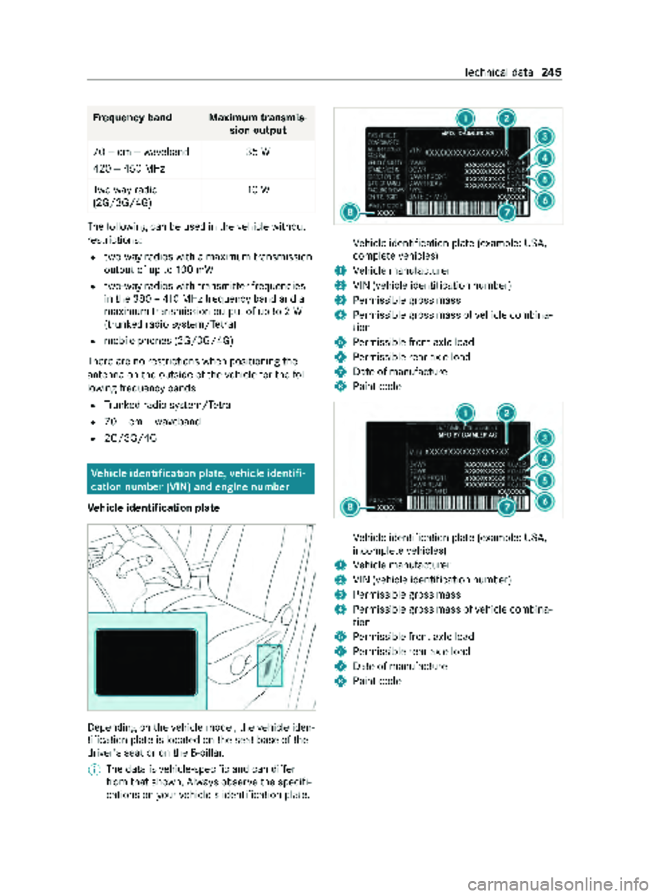
Ve hicl eidenti fication pla te Depending on
thev ehicle model, thev ehicle iden‐
tification plat eislocated on thes eat base of the
driver's seat or on theB -pillar.
% The dat
aisvehicle-speci fica nd can dif fer
from that shown. Alw ayso bser vethes pecifi‐
cation sonyourvehicle's identification plate. Ve
hicle identification plat e(example: US A,
comple te vehicles)
1 Vehicle manufacturer
2 VIN (vehicle identification number)
3 Perm issible grossmass
4 Perm issible grossmassofv ehicle combina‐
tion
5 Perm issible front axle load
6 Perm issible rear axle load
7 Dateofm anufacture
8 Paint code Ve
hicle identification plat e(example: US A,
incomple te vehicles)
1 Vehicle manufacturer
2 VIN (vehicle identification number)
3 Perm issible grossmass
4 Perm issible grossmassofv ehicle combina‐
tion
5 Perm issible front axle load
6 Perm issible rear axle load
7 Dateofm anufacture
8 Paint code Te
ch nica ldata 245
Page 248 of 316

Ve
hicle identification plat e(example: Can‐
ada, comple te vehicles)
1 Vehicle manufacturer
2 VIN (vehicle identification number)
3 Perm issible grossmass
4 Perm issible grossmassofv ehicle combina‐
tion
5 Perm issible front axle load
6 Perm issible rear axle load
7 Dateofm anufacture
8 Paint code Ve
hicle identification plat e(example: Can‐
ada, incomple te vehicles)
1 Vehicle manufacturer
2 VIN (vehicle identification number)
3 Perm issible grossmass
4 Perm issible grossmassofv ehicle combina‐
tion
5 Perm issible front axle load
6 Perm issible rear axle load
7 Dateofm anufacture
8 Paint code
The maximum permissible gross vehicle weight is
made up of thev ehicle weight ,allve hicle occu‐
pants, thef uel and thel oad. The maximum gross
axle weight rating is them aximum weight that
can be car ried byone axle (front or rear axle).
Ne vere xceed them aximum permissible gross
ve hicle weight or them aximum gross axle weight
ra ting fort he front or rear axle. The
vehicle identification plat emayalso contain
th ef ollowing data:
R Payload
R Curb weight
R Numb er of passenger seats
VIN eng rave du nde rneat hthe hood Engr
avedVIN1 is located underneat hthe hood.
VIN underneat hthe windshield The VIN is als
oattached as alabel on thel ow er
section of windshield 2.
Emission Control Information label Example: Emission Control Information label
% The dat
aisvehicle-speci fica nd can dif fer
from that shown. 246
Tech nica ldata