Page 297 of 549

*
NO
TEDama getotraile rswith a stabilisa‐
tion device against swerving In
the case of trailers with a stabilisation
device against swerving, the trailer or trailer
to w hit chcould be damaged. #
If a trailer coupling wi thTrailer Manoeu‐
vring Assist is used, on lyuse trailers
without a stabilisation device against
swerving. *
NO
TEDama gedue to ov erhanging loads
in front or dr awbar ins tallations The
vehicle and the trailer may be damaged
during manoeuvring due toove rhanging
loads at the front of the trailer or dr awbar
ins tallations. #
Pay attention to overhanging loads or
dr aw bar ins tallations while manoeu‐
vring. Tr
ailer Manoeuv ring Assi stassists you when
re ve rsing with a trailer. By means of a turning
angle sensor in the trailer coupling, Trailer Manoeuv
ring Assi stmonitors the articulation
angle between theve hicle and trailer and
adjusts it toa specified value.
Tr ailer Manoeuv ring Assi stis only an aid. It is not
a substitute foryo ur attention tothe sur round‐
ings. The responsibility for safe manoeuvring and
parking remains with you. Make sure that there
are no persons, animals or objects in the
manoeuvring area while manoeuvring and park‐
ing in/exiting parking spaces.
Yo u can either en terth e articulation angle value
directly via the multimedia sy stem or use a
st ra ightening manoeuvre. When car rying out a
st ra ightening manoeuvre, the sy stem calculates
th e articulation angle automatically and stra ight‐
ens theve hicle/trailer combination tothe trail‐
er's cur rent di rection.
Tr ailer Manoeuv ring Assi stmust be taught-in
before it can adjust the articulation angle
(/ page 294).
Obser vethe no tes on towing a trailer
(/ page 295). Sy
stem limits
The sy stem may be impaired or may not function
in thefo llowing situations:
R The gradient is more than appr oximately
15 %.
Using Trailer Manoeuvring Assist
Re quirements:
R The vehicle has been star ted and is station‐
ar y.
R A trailer has been de tected.
R The gradient is less than appr oximately 15%.
R The elect ric pa rking brake is not applied.
Te aching in Trailer Manoeuvring Assist #
Drive forw ards a short dis tance wi th the car/
trailer combination.
The comple tedte ach-in process is shown in
th e media displa y.294
Driving and parking
Page 298 of 549

%
The maximum articulation angle depends on
th e length of the trailer. This is calculated by
th e sy stem bydriving theve hicle forw ards,
including cornering. Before the length of the
trailer has been calculated, the maximum
articulation angle is appr oximately 23°. The
longer the trailer is, the higher the maximum
articulation angle (max. appr oximately 60°).
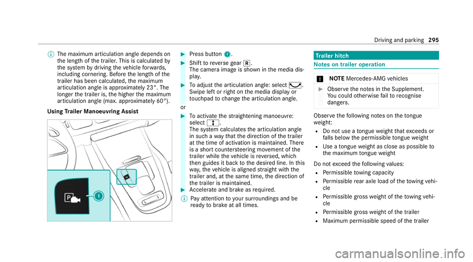
Using Trailer Manoeuvring Assist #
Press button 1. #
Shift toreve rsege ar k.
The camera image is shown in the media dis‐
pla y. #
Toadjust the articulation angle: select ¸.
Swipe left or right on the media display or
to uchpad tochange the articulation angle.
or #
Toactivate thest ra ightening manoeuvre:
select º.
The sy stem calculates the articulation angle
in such a wayth at the direction of the trailer
at the time of activation is maintained. There
is a short counter steering mo vement of the
trailer while theve hicle is reve rsed, which
th en guides it back tothe desired line. In this
wa y,theve hicle is aligned stra ight with the
trailer and, at the same time, the direction of
th e trailer is maintained. #
Accelerate and brake as requ ired.
% Pay attention toyour sur roundings and be
re ady tobrake at all times. Tr
ailer hitch Note
s on trailer operation *
NO
TEMercedes-AMG vehicles #
Obser vethe no tes in the Supplement.
Yo u could otherwise failto recognise
dangers. Obser
vethefo llowing no tes on theto ngue
we ight:
R Do not use a tongue weight that exceeds or
fa lls below the permissible tongue weight
R Use a tongue weight as close as possible to
th e maximum tongue weight
Do not exceed thefo llowing values:
R Perm issible towing capacity
R Perm issible rear axle load of theto wing vehi‐
cle
R Perm issible gross weight of theto wing vehi‐
cle
R Perm issible grossweight of the trailer
R Maximum permissible speed of the trailer Driving and parking
295
Page 299 of 549

Ensu
rethefo llowing before starting a journey:
R The tyre pressure on there ar axle of theto w‐
ing vehicle is set for a maximum load
R The lighting of the connected trailer is opera‐
tional
In theeve nt of increased rear axle load, the car/
trailer combination must not exceed a maximum
speed of 100 km/h forre asons concerning the
operating permit. This also applies in countri es
in which the permissible maximum speed for
car/trailer combinations is ab ove100 km/h.
Ve hicles with AIRMATIC or E- ACTIVE BODY
CONT ROL:ifth e soc ket of the trailer hitch is
occupied, e.g. bya trailer or rear bicycle rack,
th eve hicle is set tothe normal le velre ga rdless
of the drive program at speeds greater than
30 km/h.
% When you are reve rsing with a trailer,
re member touse theTr ailer Manoeuvering
Assist function (/ page 293). Extending and
retracting the ball ne ckfully
electrically &
WARNING Risk of accident due tothe
ball neck not being engaged
If th e ball neck is not engaged, the trailer
may come loose. #
Make sure that the ball neck securely
engages and loc ksinto place. *
NO
TEDama getothe all-electric trailer
hitch due toadditional pressure The all-electric trailer hit
chcould be mechan‐
ically damaged byapplying additional pres‐
sure when the ball neck is being extended or
re tracted. #
Do not ma kethe ball neck extend/
re tract faster by applying additional
pressure. Re
quirements:
R The vehicle is secured against rolling away.
R The swivel range is clear. R
The trailer cables or adap ter plugs ha vebeen
re mo ved.
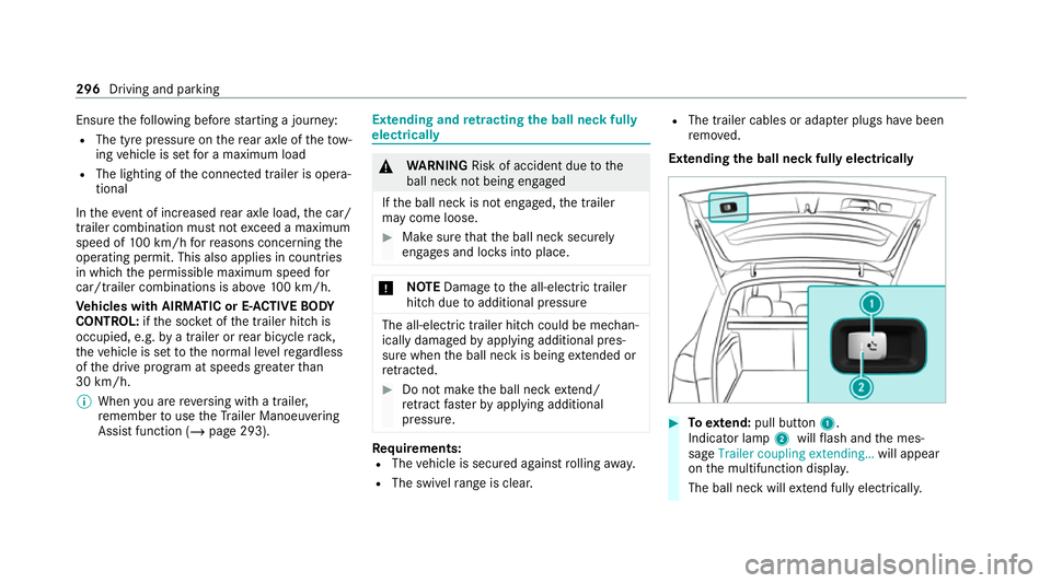
Extending the ball neck fully electrically #
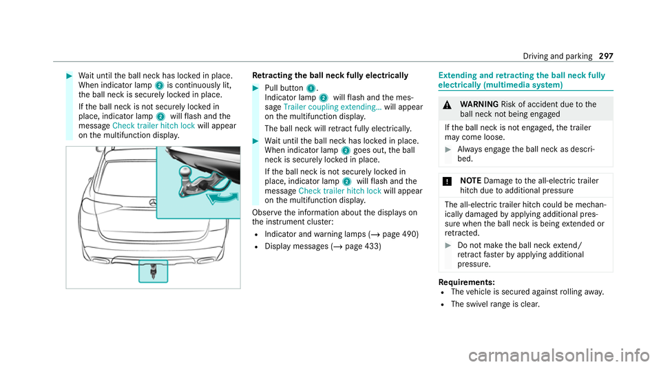
Toextend: pull button 1.
Indicator lamp 2willflash and the mes‐
sage Trailer coupling extending… will appear
on the multifunction displa y.
The ball neck will extend fully electrically. 296
Driving and pa rking
Page 300 of 549

#
Wait until the ball neck has loc ked in place.
When indicator lamp 2is continuously lit,
th e ball neck is securely loc ked in place.
If th e ball neck is not securely loc ked in
place, indicator lamp 2willflash and the
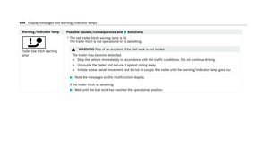
messa geCheck trailer hitch lock will appear
on the multifunction displa y. Re
tracting the ball ne ckfully electrical ly #
Pull button 1.
Indicator lamp 2willflash and the mes‐
sage Trailer coupling extending… will appear
on the multifunction displa y.
The ball neck will retract fully electrically. #
Wait until the ball neck has loc ked in place.
When indicator lamp 2goes out, the ball
neck is securely loc ked in place.
If th e ball neck is not securely loc ked in
place, indicator lamp 2willflash and the
messa geCheck trailer hitch lock will appear
on the multifunction displa y.
Obser vethe information about the displa yson
th e instrument clus ter:
R Indicator and warning lamps (/ page 490)
R Display messages (/ page 433) Extending and
retracting the ball ne ckfully
electrically (multimedia sy stem) &
WARNING Risk of accident due tothe
ball neck not being engaged
If th e ball neck is not engaged, the trailer
may come loose. #
Alw ays engage the ball neck as descri‐
bed. *
NO
TEDama getothe all-electric trailer
hitch due toadditional pressure The all-electric trailer hit
chcould be mechan‐
ically damaged byapplying additional pres‐
sure when the ball neck is being extended or
re tracted. #
Do not ma kethe ball neck extend/
re tract faster by applying additional
pressure. Re
quirements:
R The vehicle is secured against rolling away.
R The swivel range is clear. Driving and pa
rking 297
Page 301 of 549

R
The trailer cables or adap ter plugs ha vebeen
re mo ved.
Multimedia sy stem:
4 © 5
Settings 5
Quick access
Extending the ball neck fully electrically #
Select Ü.
The Trailer coupling extending… display mes‐
sage will appear on the multifunction displa y.
The ball neck will extend fully electrically. #
Wait until the ball neck has loc ked in place.
If th e ball neck is not securely loc ked in place,
th eCheck trailer hitch lock message will appear
on the multifunction displa y.
Re tracting the ball ne ckfully electrical ly#
Select Ü.
The Trailer coupling extending… displaymes‐
sage will appear on the multifunction displa y.
The ball neck will retract fully electrically. #
Wait until the ball neck has loc ked in place. If
th e ball neck is not securely loc ked in place,
th eCheck trailer hitch lock message will appear
on the multifunction displa y. Coupling/uncoupling a trailer
&
WARNING Risk of inju ryfrom theve hicle
le ve l being changed
Ve hicles with le vel control sy stem: the
ve hicle le vel may be changed unin tentional ly,
e.g. by ot her persons. You may become trap‐
ped if you couple up or uncouple a trailer
while theve hicle le vel is changing. In addi‐
tion, other people could become trapped if
th eir limbs are between theve hicle body and
th e tyres or underneath theve hicle.
When coupling up or uncoupling a trailer,
make sure that: #
The doors or tailgate are not opened or
closed. #
You do not initiate the le vel control sys‐
te m and do not operate theDY NA MIC
SELECT switch. #
Do not lock or unlock theve hicle. Re
quirements:
R The ball neck is extended and engaged in a
secu rely loc ked position.
Tr ailers with a 7-pin plug can be connec tedto
th eve hicle with thefo llowing adap ters:
R Adapter plug
R Adapter cable
The trailer will be cor rectly de tected bytheve hi‐
cle only if thefo llowing conditions are me t:
R The trailer is connected cor rectl y.
R The trailer lighting sy stem is in working
order.
The functions of thefo llowing sy stems will be
af fected bya cor rectly connected traile r:
R ESP ®
trailer stabilisation
R Trailer Manoeuvering Assist
R Active Lane Keeping Assist
R Parking Assist PARKTRONIC
R Active Parking Assist 298
Driving and parking
Page 302 of 549

R
Blind Spot Assi stor Active Blind Spot Assi st
R Drive AwayAssi st
R Cross Traf fic Alert
R Reversing camera
R 360° camera
R AIRMATIC
R E-AC TIVE BODY CONTROL
Coupling up a trailer
* NO
TEDama getothest ar ter battery due
to full dischar ge Charging
the trailer battery using the po wer
supply of the trailer can damage thest ar ter
batter y. #
Do not use theve hicle's po wer supply
to charge the trailer batter y. #
Remo vethe co ver cap from the ball head and
st ore it in a safe place. #
Position the trailer on a le vel sur face behind
th eve hicle and couple it up totheve hicle. #
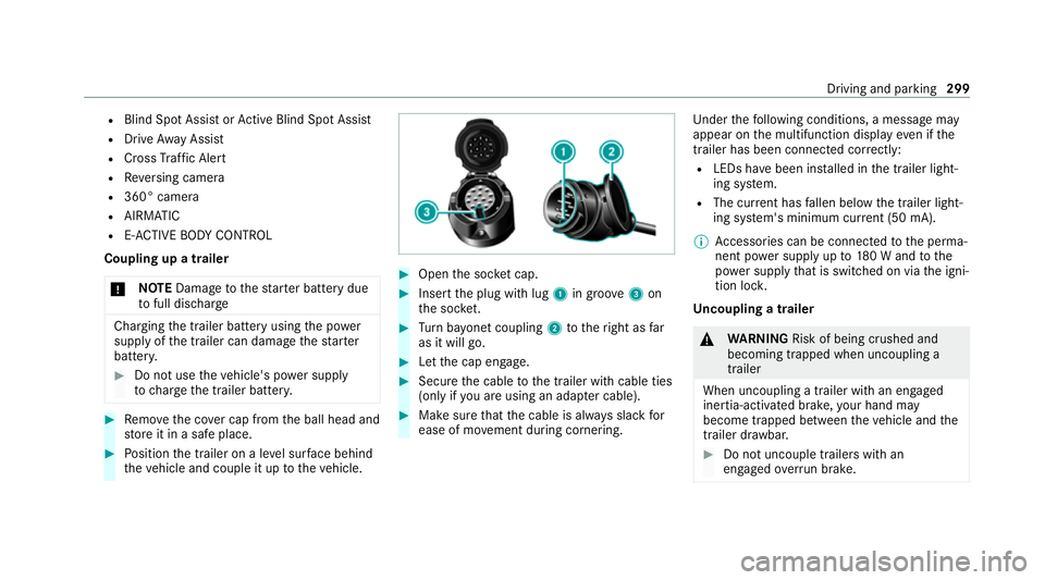
Open the soc ket cap. #
Inse rtthe plug with lug 1in groo ve3 on
th e soc ket. #
Turn bayonet coupling 2totheright as far
as it will go. #
Let the cap engage. #
Secure the cable tothe trailer with cable ties
(only if you are using an adap ter cable). #
Make sure that the cable is alw ays slack for
ease of mo vement during cornering. Under
thefo llowing conditions, a message may
appear on the multifunction display even if the
trailer has been connected cor rectly:
R LEDs ha vebeen ins talled in the trailer light‐
ing sy stem.
R The cur rent has fallen below the trailer light‐
ing sy stem's minimum cur rent (50 mA).
% Accessories can be connected tothe perma‐
nent po wer supp lyup to180 W and tothe
po we r supp lythat is swit ched on via the igni‐
tion loc k.
Un coupling a trailer &
WARNING Risk of being crushed and
becoming trapped when uncoupling a
trailer
When uncoupling a trailer wi than engaged
ine rtia-activated brake, your hand may
become trapped between theve hicle and the
trailer dr awbar. #
Do not uncouple trailers with an
engaged overrun brake. Driving and pa
rking 299
Page 303 of 549

*
NO
TEDama gewhen uncoupling in a
st ate of overrun Uncou
pling in a state of overru n can dama ge
th eve hicle. #
Do not uncouple trailers with an
engaged overrun brake. &
WARNING Risk of becoming trapped
when disconnecting the trailer cable
Ve hicles with le vel control sy stem: The
ve hicle may lo wer when the trailer cable is
disconnected.
This could result in you or other people
becoming trapped if your or their limbs are
between theve hicle body and the tyres or
underneath theve hicle. #
Make sure that nobody is unde rneath
th eve hicle or in the immediate vicinity
of the wheel ar ches when you discon‐
nect the trailer cable. *
NO
TEDama getothere ar bumper from
ins talling adap ter cables or adapte r plugs The
following parts could be damaged when
swiveling the ball neck fully electrically:
R Bumper
R Adapter cable
R Adapter plug #
Alw aysre mo vethe adap ter cable or
adapte r plug before swive lingthe ball
neck fully electrically. #
Secure the trailer against rolling away. #
Disconnect the electrical connection
between theve hicle and the trailer. #
Uncouple the trailer. #
Place the co ver cap on the ball head. Bicycle
rackfunction &
WARNING Risk of an accident when
using the bicycle rack incor rectly
The bicycle rack may become de tach ed from
th eve hicle in thefo llowing cases:
R the permissible load capacity of the
trailer hitch is exceeded.
R the bicycle rack is used incor rectl y.
R the bicycle rack is secured tothe ball
neck beneath the ball head.
Obser vethefo llowing foryo ur ow n sa fety
and that of other road users:
R always adhere tothe permissible load
capacity of the trailer hitch.
R only use the bicycle rack totranspo rt
bicycles.
R always mount the bicycle rack properly by
attaching tothe ball head and the ball
neck guide pin, if possible. 300
Driving and parking
Page 304 of 549

R
when transporting four bic ycles, alw ays
use bic ycle rack s which ha veadditional
suppo rton the ball neck guide pin.
R only use bicycle rack s appr ovedby
Mercedes-Benz.
R always obser vethe bicycle rack operating
instructions. *
NO
TEDama geto, or crac kson, the
trailer hitch due tounsuitable bic ycle
ra ck s or bicycle rack s being used incor‐
re ctly #
use only bicycle rack s appr ovedby
Mercedes-Benz. Tr
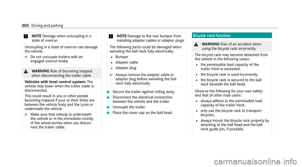
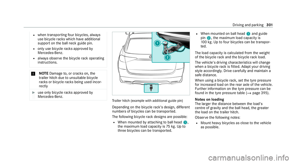
ailer hit ch(examp le with additional guide pin)
Depending on the bicycle rack 's design, dif fere nt
numbe rsof bicycles can be transpor ted.
The following bicycle rack designs are possible:
R When mounted byattaching toball head 1,
th e maximum load capacity is 75kg.Up to
th re e bicycles can be transpor ted. R
When mounted on ball head 1and guide
pin 2, the maximum load capacity is
10 0kg .Up tofour bic ycles can be transpor‐
te d.
The load capacity is calculated from thewe ight
of the bicycle rack and the bicycle rack load.
The vehicle's driving characteristics will change
when a bicycle rack isfitted. Adapt your driving
st yle accordingly. Drive carefully and maintain a
safe dis tance.
When using a bicycle rack , set the tyre pressure
fo r increased load on there ar axle of theve hicle.
Fu rther information on the tyre pressure can be
fo und in the tyre pressure table (/ page 395).
Note s on loading
The larger the dis tance between the load's
cent reof gr avity and the ball head, the greater
th e load on the trailer hitch.
Obser vethefo llowing no tes:
R Mount heavy bicycles as close totheve hicle
as possible. Driving and parking
301