Page 217 of 469

R
Ifth e lane markings change quickl y,e.g.
lanes branch off, cross one ano ther or
mer ge.
R Ifth e car riag ewa y is very nar row and wind‐
ing.
R Vehicles with Driving Assistance Pack‐
age: ifth era dar sensors in there ar bumper
are dirty or co vered in snow and an obs tacle
is de tected in your lane, no lane-cor recting
brake application take s place.
Ac tivating/deactivating Active Lane Keeping
Assist
Multimedia sy stem:
4 © 5
Settings 5
Quick access
5 Active Lane Keeping Assist #
Activate or deacti vate the function. Setting
Active Lane Keeping Assist
Multimedia sy stem:
4 © 5
Settings 5
Assistance
5 Active Lane Keeping Assist
Setting the sensitivity
% The availability of this function is dependent
on the count ry. #
Select Standard ,Sensitive orOff.
Ac tivating or deactivating the haptic warning #
Select Warning.
Ac tivate or deacti vate the function. DY
NA MIC BODY CONT ROL function DY
NA MIC BODY CONTROL continuously adjusts
th ech aracteristics of the suspension dampers to
th e cur rent operating and driving conditions.
The da mping is tuned individually for each wheel
and is af fected bythefo llowing factors:
R The road sur face conditions
R Vehicle load
R The drive program selected R
The driving style
The drive program can be adjus ted using the
DY NA MIC SELECT switch. AIR
BODY CONT ROL AIR
BODY CONT ROL function
* NO
TEMercedes-AMG vehicles #
Obser vethe no tes in the Supplement.
Yo u could otherwise failto recognise
dangers. AIR BODY
CONTROL is an air suspension sy stem
with variable damping for impr oved driving com‐
fo rt. The all-round le vel control sy stem ensures
th e best possible suspension and const ant
ground clearance, even wi tha laden vehicle.
When driving at speed, theve hicle is lo wered
automatically toimpr ovedriving saf ety and to
re duce fuel consum ption. You also ha vethe
option of manually adjusting theve hicle le vel. 214
Driving and pa rking
Page 218 of 469

AIR BODY
CONTROL includes thefo llowing com‐
ponents and functions:
R Air suspension with variable spring rate
R Automatic le vel control sy stem
R Speed-dependent lo wering toreduce fuel
consum ption
R Manually selec table high-le vel setting for
grea ter ground clea rance
R ADS PLUS (Ada ptive Damping Sy stem with
const ant damping forc e adjustment)
R DYNA MIC SELECT switch and le vel button
Suspension setting and vehicle le vel per
drive prog ram
Drive program A:
R The suspension setting is comfor table.
R The vehicle is set tothe normal le vel.
R When driving at speeds of appr oximately
12 5 km/h or abo ve,th eve hicle is lo wered.
R When driving at speeds below appr oximately
80 km/h, theve hicle is raised again. Drive program
;:
R The suspension setting is com fortable.
R The vehicle is set tolow le vel -1.
R The vehicle is not lo wered any fur ther if you
are tr avelling at higher speeds.
Drive prog ram C:
R The suspension setting is firm er.
R The vehicle is set tolow le vel -1.
R The vehicle is not lo wered any fur ther if you
are tra velling at higher speeds.
Drive prog ram B:
R The suspension setting is evenfirm er.
R The vehicle is set tolow le vel -1.
R The vehicle is not lo wered any fur ther if you
are tra velling at higher speeds.
Individual suspension settings can be called up
in drive prog ram = (/page 160). Se
tting the vehicle le vel &
WARNING Risk of accident because
ve hicle le vel is too high
Driving characteristics may be impaired.
The vehicle can drift outwards, forex ample,
when steering or cornering. #
Choose a vehicle le vel which is suited
to the driving style and thero ad sur face
conditions. &
WARNING Risk of entrapment from vehi‐
cle lo wering
When lo wering theve hicle, other people
could become trapped if their limbs are
between theve hicle body and the tyres or
underneath theve hicle. #
Make sure no one is underneath the
ve hicle or in the immediate vicinity of
th e wheel ar ches when theve hicle is
being lo wered. Driving and parking
215
Page 219 of 469

&
WARNING Risk of becoming trapped
due totheve hicle lo wering
Ve hicles with AIR BODY CONT ROL or
le ve l control sy stem: when you unload lug‐
ga ge or lea vetheve hicle, theve hicle first
ri ses slightly and then returns tothe set le vel
shortly af terw ards.
Yo u or an yone else in the vicinity of the
wheel ar ches or the underbody could thus
become trapped.
The vehicle can also be lo wered af ter being
loc ked. #
When leaving theve hicle, make sure
th at nobody is in the vicinity of the
wheel ar ches or the underbody. *
NO
TEDama gedue tovehicle lo wering Pa
rts of the body could be damaged when
th eve hicle is lo wered. #
Make sure that there are no obs tacles
such as kerbs underneath or in the immediate vicinity of
the body when the
ve hicle is being lo wered. *
NO
TEMercedes-AMG vehicles #
Obser vethe no tes in the Supplement.
Yo u could otherwise failto recognise
dangers. Re
quirements:
R The vehicle has been star ted.
R The vehicle must not be moving fasterthan
60 km/h. Ra
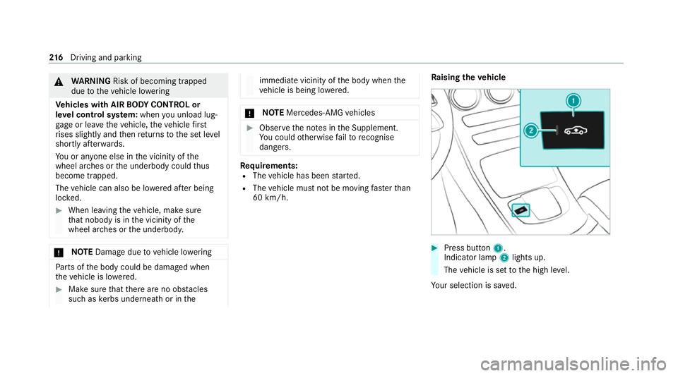
ising theve hicle #
Press button 1.
Indica tor lamp 2lights up.
The vehicle is set tothe high le vel.
Yo ur selection is sa ved. 216
Driving and pa rking
Page 220 of 469

The
vehicle is lo wered again in thefo llowing sit‐
uations:
R When driving fasterthan 80 km/h.
R When driving between 60 km/h and
80 km/h for appro ximately thre e minutes.
R Afterch anging a drive program using the
DY NA MIC SELECT switch.
The vehicle is adjus tedto the height of the last
active drive program.
Lo weri ngtheve hicle #
Press button 1.
Indica tor lamp 2goes out. The vehicle is
adjus tedto the height of the active drive pro‐
gram.
Operation with a trailer or bicycle rack
If th e electrical connection has been cor rectly
es tablished tothe trailer or bicycle rack:
R Uptoappr oximately 30 km/h: the high le vel
can be selected rega rdless of the drive pro‐
gram. R
From appr ox. 30 km/h: theve hicle is adjus‐
te dto normal le vel,re ga rdless of drive pro‐
gram. Re
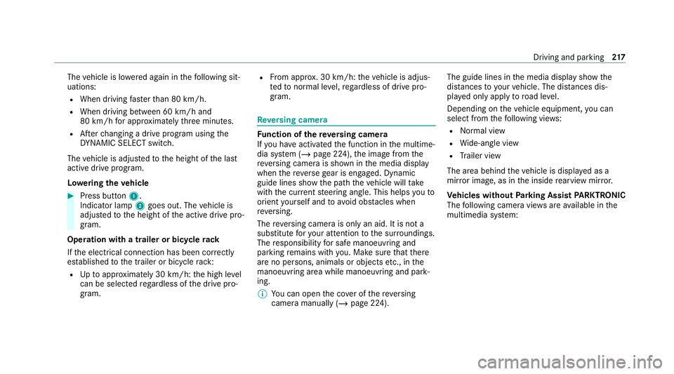
versing camera Fu
nction of there ve rsing camera
If yo u ha veactivated the function in the multime‐
dia sy stem (/ page 224), the image from the
re ve rsing camera is shown in the media display
when there ve rsege ar is engaged. Dynamic
guide lines show the path theve hicle will take
with the cur rent steering angle. This helps youto
orient yourself and toavo id obs tacles when
re ve rsing.
The reve rsing camera is only an aid. It is not a
substitute foryo ur attention tothe sur roundings.
The responsibility for safe manoeuvring and
parking remains with you. Make sure that there
are no persons, animals or objects etc., in the
manoeuvring area while manoeuvring and park‐
ing.
% You can open the co ver of there ve rsing
camera manually (/ page 224). The guide lines in
the media display show the
dis tances to yourvehicle. The dis tances dis‐
pl ay ed only apply toroad le vel.
Depending on theve hicle equipment, you can
select from thefo llowing vie ws:
R Normal view
R Wide-angle view
R Trailer view
The area behind theve hicle is displa yed as a
mir ror image, as in the inside rearview mir ror.
Ve hicles without Parking Assist PARKTRONIC
The following camera vie wsare available in the
multimedia sy stem: Driving and parking
217
Page 221 of 469
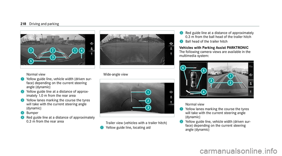
Normal view
1 Yellow guide line, vehicle width (driven sur‐
fa ce) depending on the cur rent steering
angle (dynamic)
2 Yellow guide line at a dis tance of appr ox‐
imately 1.0 m from there ar area
3 Yellow lanes marking the course the tyres
will take with the cur rent steering angle
(dynamic)
4 Bumper
5 Red guide line at a dis tance of appr oximately
0.3 m from there ar area Wi
de-angle view Tr
ailer view (vehicles with a trailer hit ch)
1 Yellow guide line, locating aid 2
Red guide line at a dis tance of appr oximately
0.3 m from the ball head of the trailer hitch
3 Ball head of the trailer hitch
Ve hicles with Parking Assist PARKTRONIC
The following camera vie wsare available in the
multimedia sy stem: Normal view
1 Yellow lanes marking the course the tyres
will take with the cur rent steering angle
(dynamic)
2 Yellow guide line, vehicle width (driven sur‐
fa ce) depending on the cur rent steering
angle (dynamic) 218
Driving and pa rking
Page 222 of 469

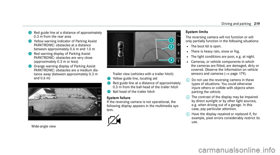
3
Red guide line at a dis tance of appr oximately
0.3 m from there ar area
4 Yellow warning indicator of Parking Assist
PA RKTRONIC: obstacles at a dis tance
between appr oximately 0.6 m and 1.0 m
5 Redwa rning display of Parking Assist
PA RKTRONIC: obstacles are very close
(appr oximately 0.3 m or less)
6 Orange warning display of Parking Assist
PA RKTRONIC: obstacles are a medium dis‐
ta nce away (between appr oximately 0.3 m
and 0.6 m) Wi
de-angle view Tr
ailer view (vehicles with a trailer hit ch)
1 Yellow guide line, locating aid
2 Red guide line at a dis tance of appr oximately
0.3 m from the ball head of the trailer hitch
3 Ball head of the trailer hitch
Sy stem failure
If th ere ve rsing camera is not operational, the
fo llowing display appears in the multimedia sys‐
te m. Sy
stem limits
The reve rsing camera will not function or will
only partially function in thefo llowing situations:
R The boot lid is open.
R There is heavy rain, snow or fog.
R The light conditions are poor, e.g. at night.
R Cameras, or vehicle components in which
th e cameras are fitted, are dama ged, dirty or
co vered. Obser vethe information on vehicle
sensors and cameras (/ page179).
% Do not use there ve rsing camera in these
types of situations. You could otherwise
injure others or collide with objects when
parking theve hicle.
% The contra stof the display may be impaired
by direct sunlight or by other light sources,
e.g. when driving out of a garage . In this
case, pay particular attention.
% Have the display repaired or replaced if, for
ex ample, pixel er rors considerably restrict its
use. Driving and pa
rking 219
Page 223 of 469

Calling up
the view of there ve rsing camera #
Press button 1.
The image from there ve rsing camera is
shown in the media displa y.
% Ifyo u ha veactivated the function, the image
from there ve rsing camera is automatically
displa yed when reve rsege ar is selec ted
( / page 224). %
Ve
hicles with Active Parking Assis t:
pressing button 1immediately displa ys the
Ac tive Parking Assist view (/ page 230). 360° Camera
Fu
nction of the 360° Camera
The 360° Camera is a sy stem that consists of
fo ur cameras. The cameras co verth e immediate
ve hicle sur roundings. The sy stem assists you
when you are parking or at exits with reduced
visibility, forex ample.
The vie wsofthe 360° Camera are alw aysav aila‐
ble when driving forw ards up toa speed of
appr ox.16 km/h and when reve rsing.
The 360° Camera is only an aid and may show a
dis torted view of obs tacles, show them incor‐
re ctly or not show them at all. It is not a substi‐
tute foryo ur attention tothe sur roundings. The
re sponsibility for safe manoeuvring and parking
re mains with you. Make sure that there are no
persons, animals or objects etc., in the manoeu‐
vring area while manoeuvring and parking. The sy
stem evaluates images from thefo llowing
cameras:
R Reversing camera
R Front camera
R Two side cameras in the outside mir rors
% You can open the co ver of there ve rsing
camera manually (/ page 224).
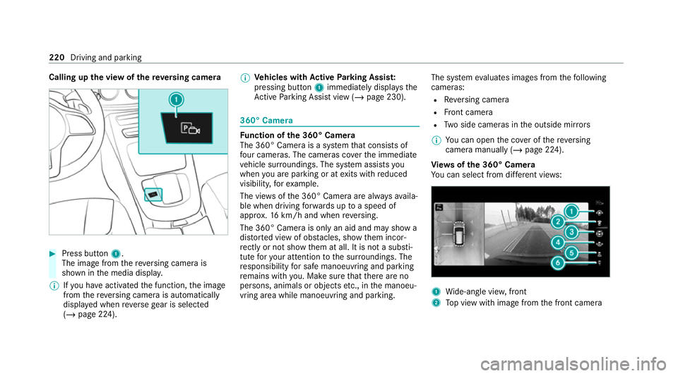
Vi ew s of the 360° Camera
Yo u can select from dif fere nt vie ws: 1
Wide-angle vie w,front
2 Top view with image from the front camera 220
Driving and parking
Page 224 of 469

3
Top view with images from the side cameras
in the outside mir rors
4 Wide-angle vie w,rear
5 Top view with image from there ve rsing cam‐
era
6 Top view with trailer view (vehicles with a
trailer hitch)
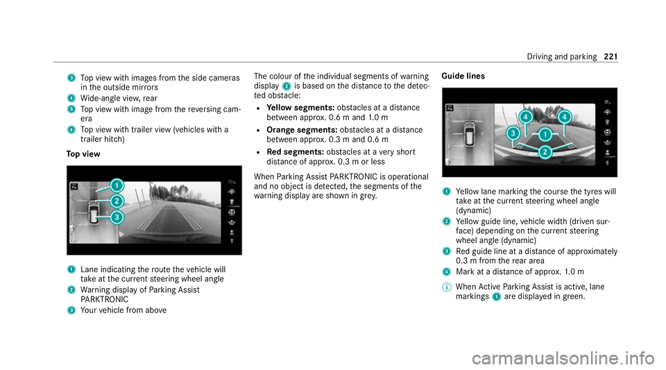
To p view 1
Lane indicating thero ute theve hicle will
ta ke atthe cur rent steering wheel angle
2 Warning display of Parking Assist
PA RKTRONIC
3 Your vehicle from abo ve The colour of
the individual segments of warning
display 2is based on the dis tance tothe de tec‐
te d obs tacle:
R Yellow segments: obstacles at a di stance
between appr ox. 0.6 m and 1.0 m
R Orange segments: obstacles at a di stance
between appr ox. 0.3 m and 0.6 m
R Red segments: obstacles at a very short
dis tance of appr ox. 0.3 m or less
When Parking Assist PARKTRONIC is operational
and no object is de tected, the segments of the
wa rning display are shown in gr ey.Guide lines 1
Yellow lane marking the course the tyres will
ta ke atthe cur rent steering wheel angle
(dynamic)
2 Yellow guide line, vehicle width (driven sur‐
fa ce) depending on the cur rent steering
wheel angle (dynamic)
3 Red guide line at a dis tance of appr oximately
0.3 m from there ar area
4 Mark at a distance of appr ox.1. 0 m
% When Active Parking Assist is active, lane
markings 1are displa yed in green. Driving and parking
221