Page 163 of 561

3-78
Convenient features of your vehicle
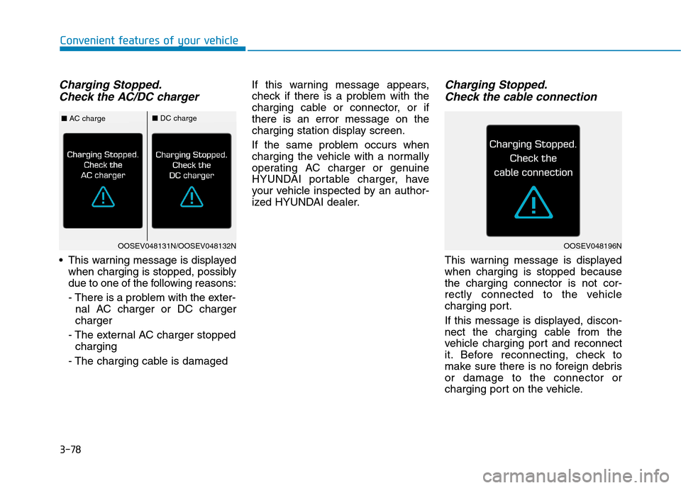
Charging Stopped.
Check the AC/DC charger
This warning message is displayed
when charging is stopped, possibly
due to one of the following reasons:
- There is a problem with the exter-
nal AC charger or DC charger
charger
- The external AC charger stopped
charging
- The charging cable is damagedIf this warning message appears,
check if there is a problem with the
charging cable or connector, or if
there is an error message on the
charging station display screen.
If the same problem occurs when
charging the vehicle with a normally
operating AC charger or genuine
HYUNDAI portable charger, have
your vehicle inspected by an author-
ized HYUNDAI dealer.
Charging Stopped.
Check the cable connection
This warning message is displayed
when charging is stopped because
the charging connector is not cor-
rectly connected to the vehicle
charging port.
If this message is displayed, discon-
nect the charging cable from the
vehicle charging port and reconnect
it. Before reconnecting, check to
make sure there is no foreign debris
or damage to the connector or
charging port on the vehicle.
OOSEV048131N/OOSEV048132N
■AC charge■DC charge
OOSEV048196N
Page 177 of 561

3-92
Convenient features of your vehicle
ItemsExplanation
Seat Easy Access
The seat easy access function is deactivated.
When you turn off the vehicle, the driver's seat will automatically move rearward
short (Normal) or long (Extended) for you to enter or exit the vehicle more comfortably.
For more details, refer to "Driver Position Memory System" in this chapter.
Charge Connector Lock ModeTo activate the charge connector lock.
Switch to utility mode?
To activate the utility mode.
When activated, electric devices in the vehicle is operated using the high voltage battery.
For more details, refer to "Utility Mode" in the Electric Vehicle Guide in front of the owner's manual.
Welcome Mirror/LightTo activate or deactivate the welcome mirror and/or light function.
For more details, refer to ''Welcome System'' in this chapter.
Wireless Charging SystemTo activate or deactivate the wireless charging system in the front seat.
For more details, refer to "Wireless Charging System" in this chapter.
Wiper/Lights DisplayTo activate or deactivate the Wiper/Light mode.
When activated, the LCD display shows the selected Wiper/Light mode whenever you changed the
mode.
Smart Regeneration
To activate or deactivate the Smart Regeneration function. When activated, the regeneration level is
adjusted automatically according to the current driving situation.
For more details, refer to "Smart Regeneration System" in chapter 5.
Icy Road WarningTo activate or deactivate the icy road warning.
5. Convenience
❈ ❈
The information provided may differ depending on which functions are applicable to your vehicle.
Page 398 of 561
6-16
What to do in an emergency
1. Speed restriction label
2. Sealant bottle and label with
speed restriction
3. Filling hose from sealant bottle to
wheel
4. Connectors and cable for power
outlet direct connection5. Holder for the sealant bottle
6. Compressor
7. ON/OFF switch
8. Pressure gauge for displaying the
tire inflation pressure
9. Button for reducing tire inflation
pressureConnectors, cable and connection
hose are stored in the compressor
housing.
Strictly follow the specified sequence,
otherwise the sealant may escape
under high pressure.
Components of the Tire Mobility Kit
ODE067044
Do not use the tire sealant after
the sealant has expired (i.e.
past the expiration date on the
sealant container). This can
increase the risk of tire failure.
WARNING
Keep out of reach of children.
Avoid contact with eyes.
Do not swallow.
WARNING
Page 399 of 561
6-17
What to do in an emergency
6
Using the Tire Mobility Kit
1. Detach the speed restriction label
from the sealant bottle, and place
it in a highly visible place inside
the vehicle such as on the steer-
ing wheel to remind the driver not
to drive too fast.2. Shake the sealant bottle (2).
3. Screw the filling hose (3) onto the
connector of the sealant bottle.
4. Ensure that the ON/OFF switch on
the compressor is in the OFF posi-
tion.5. Unscrew the valve cap from the
valve of the flat tire and screw the
filling hose (3) of the sealant bottle
onto the valve.
OIGH067042
OAEPH068014
OAEE069005
Page 400 of 561
6-18
What to do in an emergency
Securely install the sealant filling
hose to the valve. If not, sealant
may flow backward, possibly clog-
ging the filling hose.
6. Plug the compressor power cord
(4) into the vehicle power outlet.
7. With the vehicle ON ( indica-
tor ON), switch on the compressor
and let it run for approximately
5~7 minutes to fill the sealant up
to proper pressure. (refer to the
Tire and Wheels, chapter 8). The
inflation pressure of the tire after
filling is unimportant and will be
checked/corrected later.
Be careful not to overinflate the
tire and stay away from the tire
when filling it.8. Switch off the compressor.
9. Detach the hoses from the sealant
bottle connector and from the tire
valve.
Return the Tire Mobility Kit to its stor-
age location in the vehicle.
NOTICE
OAEE069006
OAEE069008
Do not attempt to drive your
vehicle if the tire pressure is
below 29 psi (200 kpa). This
could result in an accident due
to sudden tire failure.
CAUTION
Page 451 of 561
7-45
7
Maintenance
Fuse NameFuse RatingProtected Component
MODULE210AE/R Junction Block (Power Outlet Relay), Wireless Charger Unit, SBW Switch, BCM, USB Charging,
Smart Key Control Module, Audio, A/V & Navigation Head Unit, Power Outside Mirror Switch, AMP
PDM37.5ASmart Key Control Module
MEMORY110AAuto Light & Photo Sensor, Driver IMS Module, BCM, A/C Control Module, Instrument Cluster,
Passenger Door Module, Driver Door Module, Electro Chromic Mirror Relay Box
(Outside Mirror Folding/Unfolding Relay)
MULTIMEDIA10AA/V & Navigation Head Unit, Audio
E-SHIFTER210ASCU
IG3 310ACCM Unit
IG3 120AICM Relay Box
MDPS7.5AMDPS Unit
T/GATE10ATail Gate Relay, Main Battery Charging Switch, Quick Charging Connector Door Lock/Unlock Actuator
PDM115ASmart Key Control Module
MODULE77.5AFront Seat Warmer Control Module, Front Air Ventilation Seat Control Module, Rear Seat Warmer Module
HTD STRG15ABCM
Instrument panel fuse panel
Page 452 of 561
7-46
Maintenance
Fuse NameFuse RatingProtected Component
SUNROOF20ASunroof Motor
P/WDW RH25APower Window (RH) Relay, Passenger Safety Power Window Switch
P/WDW LH25ADriver Safety Power Window Module
PDM27.5ASmart Key Control Module, Start/Stop Button Switch
BRAKE
SWITCH7.5AStop Lamp Switch, Smart Key Control Module
OBC10AOBC
A/CON7.5AA/C Control Module
WASHER15AMultifunctioEt Warmer Control Module, Front Air Ventilation Seat Control Module
S/HEATER
FRT25ACharging Connector Lamp, Quick Charging Connector Lamp
CHARGER10ACCM Unit, Charging Connector Lamp, ICM Relay Box (Charging Connector Lock/Unlock Relay)
P/SEAT DRV30ADriver Seat Manual Switch, Driver IMS Module
AMP30AAMP
Instrument panel fuse panel
Page 453 of 561
7-47
7
Maintenance
Fuse NameFuse RatingProtected Component
MODULE110AData Link Connector, FCA Unit, Driver/Passenger Power Outside Mirror,
Driver/Passenger Smart Key Outside Handle, Driver/Passenger Door Module
DOOR LOCK20ADoor Lock/Unlock Relay, ICM Relay Box (Two Turn Unlcok Relay)
WIPER FRT210AWiper Motor, PCB Block (Front Wiper (Low) Relay) BCM
MODULE67.5ASmart Key Control Module, BCM
S/HEATER RR25ARear Seat Warmer Module
HTD MIRR10ADriver/Passenger Power Outside Mirror, A/C Control Module
RR HTD25ARear Defogger (+) (Upper)
WIPER FRT130AWiper Motor, PCB Block (Front Wiper (Low) Relay), A/C Control Module
Instrument panel fuse panel