Page 137 of 244

135
Practical information07
If in doubt
Domestic or accelerated charging: do
not remain inside or near the vehicle, or near
the charging cable or charging unit, even for a
short time.
Fast charging: do not use the system yourself
and avoid approaching public fast charging
points. Leave the area and ask a third party to
recharge the vehicle.
For domestic or accelerated charging
Before charging
Depending on the context:
► Have a professional check that the
electrical system to be used complies with
applicable standards and is compatible with
the vehicle.
► Have a professional electrician install
a dedicated domestic power socket or
accelerated charging unit (Wallbox)
compatible with the vehicle.
Use the charging cable supplied with the
vehicle.
(During charging)
Never work under the bonnet:
–
Some areas remain v
ery hot, even an hour
after charging ends - risk of burns!
–
The fan ma
y start at any time - risk of cuts or
strangulation!
After charging
Check that the charging flap is closed.
Do not leave the cable connected to the
domestic power socket - risk of short-circuit
or electrocution in the event of contact with or
immersion in water!
For fast charging
Before charging
Check that the fast public charger and
its charging cable are compatible with your
vehicle.
If the exterior temperature is below :
–
-25
°C, charging may not be possible.
–
0°C
, charging times may be extended.
(During charging)
Do not remain in or near the vehicle.
While charging is in progress, opening the
driver's door will interrupt charging.
After charging
Check that the charging flap is closed.
Connection
► Before charging, check that the drive selector
is in mode P and the ignition is off, otherwise
charging is not possible. ►
Open the charging flap by pressing the push-
button, and check that there are no foreign bodies
on the charging connector.
Domestic charging
► Connect the charging cable from the control
unit to the domestic socket.
When the connection is made, all of the indicator
lamps on the control unit light up, then only the
POWER indicator lamp remains on in green.
► Remove the protective cover from the
charging nozzle.
► Insert the nozzle into the charging connector.
The start of charging is confirmed by the flashing
in green of the CHARGE indicator lamps in the
flap, then on the control unit.
If this is not the case, charging has not started;
restart the procedure, ensuring that all
connections are properly established.
Page 138 of 244

136
Practical information07
The red indicator lamp in the flap comes on to
indicate that the nozzle is locked.
If charging has finished but the cable is
still connected, opening the driver's door
restarts charging for around 20 seconds.
Accelerated charging
► Follow the instructions for use of the
accelerated charging unit (Wallbox).
► Remove the protective cover from the
charging nozzle.
► Insert the nozzle into the charging connector.
The start of charging is confirmed when the
charging indicator lamp in the flap flashes green.
If this is not the case, charging has not started;
restart the procedure, ensuring that the nozzle is
inserted correctly.
The red indicator lamp in the flap comes on to
indicate that the nozzle is locked.
Fast charging
► Depending on version, remove the protective
cover from the base.
► Connect the charging cable to the vehicle
connector, following the instructions for use of
the fast public charger.
The start of charging is confirmed when the
charging indicator lamp in the flap flashes green.
If this is not the case, charging has not started;
restart the procedure, ensuring that the
connection is correct.
The red indicator lamp in the flap comes on to
indicate that the nozzle is locked.
Disconnection
Before disconnecting the nozzle from the
charging connector:
► If the vehicle is unlocked, lock it and then
unlock it.
► If the vehicle is locked, unlock it. The red indicator lamp in the flap goes out to
confirm that the charging nozzle is unlocked.
►
Within 30 seconds, remove the charging
nozzle.
Domestic charging
When charging is complete, the green CHARGE
indicator lamp on the control unit comes on fixed.
► Replace the protective cover on the charging
nozzle and close the charging flap.
► Disconnect the control unit end of the
charging cable from the domestic socket.
Accelerated charging
The end of charging is indicated by the charging
control unit and by the fixed lighting of the green
indicator lamp in the flap.
► Hang up the nozzle on the charging unit and
close the charging flap.
Fast charging
The end of charging is indicated by the charger
and by the fixed lighting of the green indicator
lamp in the flap.
► Hang up the nozzle on the charging station.
► Depending on version, replace the protective
cover on the base and close the charging flap.
Towing device
Load distribution
► Distribute the load in the trailer so that
the heaviest items are as close as possible to
the axle, and the nose weight approaches the
maximum permitted without exceeding it.
Air density decreases with altitude, thus reducing
engine performance. The maximum load which
can be towed must be reduced by 10% per
1,000 metres of altitude.
Use towing devices and their genuine
wiring harnesses approved by the
Manufacturer. It is recommended that the
Page 139 of 244

137
Practical information07
Accelerated charging
The end of charging is indicated by the charging
control unit and by the fixed lighting of the green
indicator lamp in the flap.
► Hang up the nozzle on the charging unit and
close the charging flap.
Fast charging
The end of charging is indicated by the charger
and by the fixed lighting of the green indicator
lamp in the flap.
► Hang up the nozzle on the charging station.
► Depending on version, replace the protective
cover on the base and close the charging flap.
Towing device
Load distribution
► Distribute the load in the trailer so that
the heaviest items are as close as possible to
the axle, and the nose weight approaches the
maximum permitted without exceeding it.
Air density decreases with altitude, thus reducing
engine performance. The maximum load which
can be towed must be reduced by 10% per
1,000 metres of altitude.
Use towing devices and their genuine
wiring harnesses approved by the
Manufacturer. It is recommended that the
fitting be performed by a dealer or a qualified
workshop.
If not fitted by a dealer, it must still be fitted
in accordance with the Manufacturer's
instructions.
Certain driving or manoeuvring aid functions
are automatically deactivated if an approved
towing system is used.
Observe the maximum authorised towable
weight, indicated on the vehicle's
registration certificate, the manufacturer's
label as well as in the Technical data section of
this guide.
Complying with the maximum authorised
nose weight (towball) also includes the use of
accessories (bicycle carriers, tow boxes, etc.).
Observe the legislation in force in the
country where you are driving.
Electric motor
Electric vehicles must never be equipped
with towing devices.
It is therefore not possible to tow a trailer or
caravan.
Roof bars
As a safety measure and to avoid
damaging the roof, it is essential to use
the transverse bars approved for the vehicle.
Observe the instructions on fitting and use
contained in the guide supplied with the roof
bars.
To install the roof bars, you must secure them
only to the four fixing points on the roof frame.
These points are concealed by the vehicle's doors
when they are closed.
The roof bar fixings include a lug to be fitted into
the hole at each fixing point.
Maximum load distributed over the roof
bars, for a loading height not exceeding
40 cm: 75 kg.
As this value may change, please verify the
maximum load set out in the manual supplied
with the roof bars.
Page 140 of 244

138
Practical information07
If the height exceeds 40 cm, adapt the speed
of the vehicle to the profile of the road to avoid
damaging the roof bars and the fixings on the
vehicle.
Be sure to refer to national legislation in order
to comply with the regulations for transporting
objects which are longer than the vehicle.
Recommendations
Distribute the load uniformly, taking care
to avoid overloading one of the sides.
Arrange the heaviest part of the load as close
as possible to the roof.
Secure the load firmly.
Drive gently: the vehicle will be more
susceptible to the effects of side winds and its
stability may be affected.
Regularly check the security and tight
fastening of the roof bars, at least before each
trip.
Remove the roof bars once they are no longer
needed.
Snow chains
In wintry conditions, snow chains improve
traction as well as the behaviour of the vehicle
when braking.
The snow chains must be fitted only to
the front wheels. They must never be
fitted to "space-saver" type spare wheels.
Take account of the legislation specific to
each country on the use of snow chains
and the maximum authorised speed.
Use only chains designed to be fitted to the type
of wheel fitted to the vehicle:
Original tyre size Chain type 215/65 R16 Cannot be fitted with chains
215/60 R17 Polaire XP9 with manual locking
215/55R18 Cannot be fitted with chains
For more information on snow chains, contact a
dealer or a qualified workshop.
Installation tips
► To fit the chains during a journey, stop the
vehicle on a flat surface on the side of the road.
► Apply the parking brake and position any
wheel chocks under the wheels to prevent
movement of the vehicle.
► Fit the chains following the instructions
provided by the manufacturer.
► Move off gently and drive for a few moments,
without exceeding 31 mph (50 km/h).
► Stop the vehicle and check that the snow
chains are correctly tightened.
It is strongly recommended that before
you leave, you practise fitting the snow
chains on a level and dry surface.
Avoid driving with snow chains on roads
that have been cleared of snow to avoid
damaging the vehicle's tyres and the road
surface. If the vehicle is fitted with alloy
wheels, check that no part of the chain or its
fixings is in contact with the wheel rim.
Energy economy mode
This system manages the duration of use of
certain functions, in order to conserve a sufficient
level of charge in the battery with the ignition off.
After switching off the engine, you can still
use functions such as the audio and telematic
system, the wipers and the dipped beam
headlamps or courtesy lamps, for a combined
duration of approximately 40 minutes.
Selecting the mode
A confirmation message is displayed when
energy economy mode is entered, and the active
functions are placed on standby.
If a telephone call is in progress at the
time, it will be maintained for around 10
minutes via the audio system’s hands-free
system.
Exiting the mode
These functions are automatically reactivated the
next time the vehicle is used.
To restore the use of these functions immediately,
start the engine and let it run:
– For less than 10 minutes, to use the equipment
for approximately 5 minutes.
– For more than 10 minutes, to use the equipment
for approximately 30 minutes.
Let the engine run for the specified duration to
ensure that the battery charge is sufficient.
To recharge the battery, avoid repeatedly or
continuously restarting the engine.
A flat battery prevents the engine from
starting.
For more information on the 12 V battery, refer
to the corresponding section.
Load reduction mode
This system manages the use of certain functions
according to the level of charge remaining in the
battery.
When the vehicle is being driven, the load
reduction function temporarily deactivates
certain functions, such as the air conditioning
and the heated rear screen.
The deactivated functions are reactivated
automatically as soon as conditions permit.
Page 141 of 244

139
Practical information07
Exiting the mode
These functions are automatically reactivated the
next time the vehicle is used.
To restore the use of these functions immediately,
start the engine and let it run:
–
For le
ss than 10 minutes, to use the equipment
for approximately 5 minutes.
–
For more than 10 minut
es, to use the equipment
for approximately 30 minutes.
Let the engine run for the specified duration to
ensure that the battery charge is sufficient.
To recharge the battery, avoid repeatedly or
continuously restarting the engine.
A flat battery prevents the engine from
starting.
For more information on the 12 V battery, refer
to the corresponding section.
Load reduction mode
This system manages the use of certain functions
according to the level of charge remaining in the
battery.
When the vehicle is being driven, the load
reduction function temporarily deactivates
certain functions, such as the air conditioning
and the heated rear screen.
The deactivated functions are reactivated
automatically as soon as conditions permit.
Bonnet
Stop & Start
Before doing anything under the bonnet,
you must switch off the ignition to avoid any
risk of injury resulting from an automatic
change to START mode.
The location of the interior bonnet release
lever prevents the bonnet being opened
when the left-hand front door is closed.
When the engine is hot, handle the
exterior safety catch and the bonnet stay
with care (risk of burns), using the protected
area.
When the bonnet is open, take care not to
damage the safety catch.
Do not open the bonnet under very windy
conditions.
Cooling of the engine when stopped
The engine cooling fan may start after the
engine has been switched off.
Take care with objects or clothing that could
be caught in the blades of the fan!
Opening
► Open the left-hand front door.
► Pull the interior release lever, located at the
bottom of the door frame, towards you.
► Lift the exterior safety catch and raise the
bonnet.
► Unclip the stay from its housing and place it in
the support slot to hold the bonnet open.
Closing
► Hold the bonnet and pull out the stay from the
support slot.
Page 142 of 244

140
Practical information07
► Clip the stay in its housing.
► Lower the bonnet and release it near the end
of its travel.
► Pull on the bonnet to check that it is locked
correctly.
Because of the presence of electrical
equipment under the bonnet, it is
recommended that exposure to water (rain,
washing, etc.) be limited.
Engine compartment
The engine represented is an example given for
illustration purposes only.
The locations of the following elements may vary:
–
Air filt
er.
–
Engine oil dip
stick.
–
Engine oil filler c
ap.
Petrol engine
Diesel engine
1.Screenwash fluid reservoir.
2.Engine coolant reservoir.
3.Brake fluid reservoir.
4.Battery/Fuses.
5.Remote earth point (-).
6.Fusebox.
7. Air filter.
8.Engine oil filler cap.
9.Engine oil dipstick.
The Diesel fuel system operates under
very high pressure.
All work on this circuit must be carried out only
by a dealer or a qualified workshop.
Electric motor
1. Screenwash fluid reservoir
2. Engine coolant reservoir
3.Brake fluid reservoir
4. Battery / Fuses
5. Remote earth point (-)
6. Fusebox
7. 400 V electrical system
8. Emergency circuit-breaker for firefighters and
maintenance technicians
For more information on the Charging system
(Electric), refer to the corresponding section.
Checking levels
Check all of the following levels regularly in
accordance with the manufacturer's service
schedule. Top them up if required, unless
otherwise indicated.
If a level drops significantly, have the
corresponding system checked by a dealer or a
qualified workshop.
The fluids must comply with the
manufacturer's requirements and with
the vehicle's engine.
Take care when working under the
bonnet, as certain areas of the engine
may be extremely hot (risk of burns) and the
cooling fan could start at any time (even with
the ignition off).
Used products
Avoid prolonged contact of used oil or
fluids with the skin.
Most of these fluids are harmful to health and
very corrosive.
Do not discard used oil or fluids into
sewers or onto the ground.
Empty used oil into the containers reserved
for this purpose at a dealer or a qualified
workshop.
Engine oil
The level is checked, with the engine
having been switched off for at least 30
minutes and on level ground, using the dipstick.
It is normal to top up the oil level between two
services (or oil changes). It is recommended that
you check the level, and top up if necessary, every
3,000 miles (5,000 km).
In order to maintain the reliability of the
engine and emissions control system,
never use additives in the engine oil.
Checking using the dipstick
For the location of the dipstick, please refer
to the illustration of the corresponding engine
compartment.
► Grasp the dipstick by its coloured grip and pull
it out completely.
Page 143 of 244

141
Practical information07
Used products
Avoid prolonged contact of used oil or
fluids with the skin.
Most of these fluids are harmful to health and
very corrosive.
Do not discard used oil or fluids into
sewers or onto the ground.
Empty used oil into the containers reserved
for this purpose at a dealer or a qualified
workshop.
Engine oil
The level is checked, with the engine
having been switched off for at least 30
minutes and on level ground, using the dipstick.
It is normal to top up the oil level between two
services (or oil changes). It is recommended that
you check the level, and top up if necessary, every
3,000 miles (5,000 km).
In order to maintain the reliability of the
engine and emissions control system,
never use additives in the engine oil.
Checking using the dipstick
For the location of the dipstick, please refer
to the illustration of the corresponding engine
compartment.
► Grasp the dipstick by its coloured grip and pull
it out completely.
► Wipe the end of the dipstick using a clean, lint-
free cloth.
► Reinsert the dipstick and push fully down,
then pull it out again to visually check the oil level:
the correct level is between marks A (max) and
B (min).
Do not start the engine if the level is:
–
abo
ve mark A: contact a dealer or a qualified
workshop.
–
belo
w mark B: top up the engine oil
immediately.
Oil grade
Before topping up or changing the engine
oil, check that the oil is suitable for the engine
and complies with the recommendations in
the service schedule supplied with the vehicle
(or available from your dealer and qualified
workshops).
Use of non-recommended oil may invalidate
the contractual warranty in the event of engine
failure.
Topping up the engine oil level
For the location of the engine oil filler cap, please
refer to the corresponding under-bonnet engine
compartment illustration.
► Add oil in small quantities, avoiding any spills
on engine components (risk of fire).
► Wait a few minutes before checking the level
again using the dipstick.
► Top up the level if necessary.
► After checking the level, carefully screw the
oil filler cap back on and replace the dipstick in
its tube.
Within 30 minutes of adding oil, the oil
level indication in the instrument panel
when the ignition is switched on is not valid.
Brake fluid
The level of this fluid should be close to the
"MAX" mark. If not, check the brake pad
wear.
To know how often the brake fluid should be
replaced, refer to the manufacturer's servicing
schedule.
Clean the cap before removing it to refill.
Use only DOT4 brake fluid from a sealed
container.
Engine coolant
It is normal to top up this fluid between
two services.
Page 144 of 244

142
Practical information07
The check and top-up must only be done with the
engine cold.
A low level presents a risk of serious damage to
the engine.
The level of this fluid should be close to the "MAX"
mark but should never exceed it.
If the level is close to or below the "MIN” mark, it
is essential to top up.
When the engine is hot, the temperature of this
fluid is regulated by the fan.
As the cooling system is pressurised, wait at least
one hour after switching off the engine before
carrying out any work.
In order to avoid the risk of scalding if you need to
top up in an emergency, wrap a cloth around the
cap and unscrew the cap by two turns to allow the
pressure to drop.
Once the pressure has dropped, remove the cap
and top up to the required level.
Screenwash fluid
Top up to the required level when
necessary.
Fluid specification
The fluid must be topped up with a ready-to-use
mixture.
In winter (temperatures below zero), a liquid
containing an agent to prevent freezing must
be used which is appropriate for the prevailing
conditions, in order to protect the elements of the
system (pump, tank, ducts, jets, etc.).
Filling with pure water is prohibited under
all circumstances (risk of freezing,
limestone deposits, etc.).
AdBlue (BlueHDi)
An alert is triggered when the reserve level is
reached.
For more information on Indicators and in
particular the AdBlue range indicators, refer to
the corresponding section.
To avoid the vehicle being immobilised in
accordance with regulations, you must top up the
AdBlue tank.
For more information on AdBlue
® (BlueHDi), and
in particular on the supply of AdBlue, refer to the
corresponding section.
Checks
Unless otherwise indicated, check these
components in accordance with the
manufacturer's service schedule and according to
your engine.
Otherwise, have them checked by a dealer or a
qualified workshop.
Only use products recommended by the
Manufacturer or products of equivalent
quality and specification.
In order to optimise the operation of
components as important as those in the
braking system, the Manufacturer selects and
offers very specific products.
12 V battery
The battery does not require any
maintenance.
However, check regularly that the terminals
are correctly tightened (versions without quick
release terminals) and that the connections are
clean.
For more information on the precautions
to take before any work on the 12 V
battery, refer to the corresponding section.
Versions equipped with Stop & Start are
fitted with a 12 V lead-acid battery of
specific technology and specification.
Its replacement should be carried out only by a
dealer or by a qualified workshop.
Passenger compartment filter
Depending on the environment and the use
of the vehicle (e.g. dusty atmosphere, city
driving), change it twice as often, if necessary.
A clogged passenger compartment filter
can adversely affect air conditioning
system performance and generate undesirable
odours.
Air filter
Depending on the environment and the use
of the vehicle (e.g. dusty atmosphere, city
driving), change it twice as often, if necessary.
Oil filter
Change the oil filter each time the engine
oil is changed.
Particle filter (Diesel)
When the particle filter is approaching
saturation, this warning lamp comes on
temporarily, accompanied by a message warning
of the risk of filter clogging.
As soon as the traffic conditions permit,
regenerate the filter by driving at a speed of at
least 37 mph (60 km/h) until the warning lamp
goes off.
Following prolonged operation of the
vehicle at very low speed or at idle, you
may, in exceptional circumstances, notice the
emission of water vapour at the exhaust while
accelerating. This has no impact on the
vehicle’s behaviour or the environment.
New vehicle
During the first few particle filter
regeneration operations, you may notice a
"burning" smell. This is perfectly normal.
Manual gearbox
The gearbox does not require any
maintenance (no oil change).
 1
1 2
2 3
3 4
4 5
5 6
6 7
7 8
8 9
9 10
10 11
11 12
12 13
13 14
14 15
15 16
16 17
17 18
18 19
19 20
20 21
21 22
22 23
23 24
24 25
25 26
26 27
27 28
28 29
29 30
30 31
31 32
32 33
33 34
34 35
35 36
36 37
37 38
38 39
39 40
40 41
41 42
42 43
43 44
44 45
45 46
46 47
47 48
48 49
49 50
50 51
51 52
52 53
53 54
54 55
55 56
56 57
57 58
58 59
59 60
60 61
61 62
62 63
63 64
64 65
65 66
66 67
67 68
68 69
69 70
70 71
71 72
72 73
73 74
74 75
75 76
76 77
77 78
78 79
79 80
80 81
81 82
82 83
83 84
84 85
85 86
86 87
87 88
88 89
89 90
90 91
91 92
92 93
93 94
94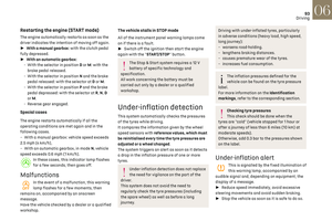 95
95 96
96 97
97 98
98 99
99 100
100 101
101 102
102 103
103 104
104 105
105 106
106 107
107 108
108 109
109 110
110 111
111 112
112 113
113 114
114 115
115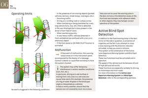 116
116 117
117 118
118 119
119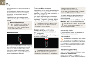 120
120 121
121 122
122 123
123 124
124 125
125 126
126 127
127 128
128 129
129 130
130 131
131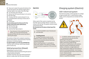 132
132 133
133 134
134 135
135 136
136 137
137 138
138 139
139 140
140 141
141 142
142 143
143 144
144 145
145 146
146 147
147 148
148 149
149 150
150 151
151 152
152 153
153 154
154 155
155 156
156 157
157 158
158 159
159 160
160 161
161 162
162 163
163 164
164 165
165 166
166 167
167 168
168 169
169 170
170 171
171 172
172 173
173 174
174 175
175 176
176 177
177 178
178 179
179 180
180 181
181 182
182 183
183 184
184 185
185 186
186 187
187 188
188 189
189 190
190 191
191 192
192 193
193 194
194 195
195 196
196 197
197 198
198 199
199 200
200 201
201 202
202 203
203 204
204 205
205 206
206 207
207 208
208 209
209 210
210 211
211 212
212 213
213 214
214 215
215 216
216 217
217 218
218 219
219 220
220 221
221 222
222 223
223 224
224 225
225 226
226 227
227 228
228 229
229 230
230 231
231 232
232 233
233 234
234 235
235 236
236 237
237 238
238 239
239 240
240 241
241 242
242 243
243