2020 CHRYSLER 300 buttons
[x] Cancel search: buttonsPage 26 of 328
24GETTING TO KNOW YOUR VEHICLE
POWER DOOR LOCKS
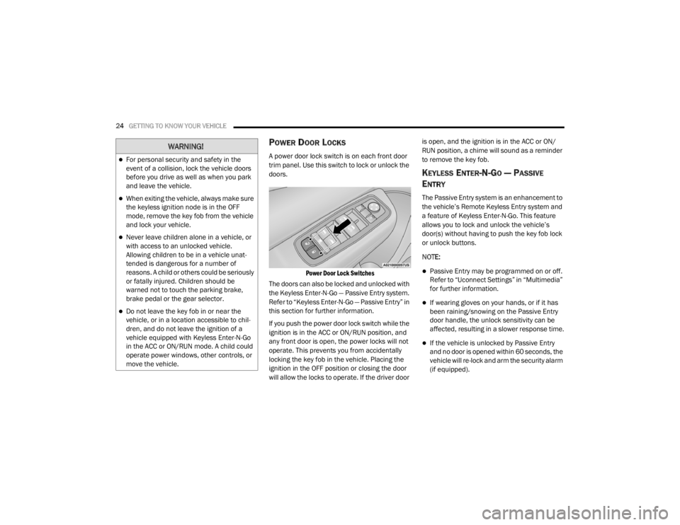
A power door lock switch is on each front door
trim panel. Use this switch to lock or unlock the
doors.
Power Door Lock Switches
The doors can also be locked and unlocked with
the Keyless Enter-N-Go — Passive Entry system.
Refer to “Keyless Enter-N-Go — Passive Entry” in
this section for further information.
If you push the power door lock switch while the
ignition is in the ACC or ON/RUN position, and
any front door is open, the power locks will not
operate. This prevents you from accidentally
locking the key fob in the vehicle. Placing the
ignition in the OFF position or closing the door
will allow the locks to operate. If the driver door is open, and the ignition is in the ACC or ON/
RUN position, a chime will sound as a reminder
to remove the key fob.
KEYLESS ENTER-N-GO — PASSIVE
E
NTRY
The Passive Entry system is an enhancement to
the vehicle’s Remote Keyless Entry system and
a feature of Keyless Enter-N-Go. This feature
allows you to lock and unlock the vehicle’s
door(s) without having to push the key fob lock
or unlock buttons.
NOTE:
Passive Entry may be programmed on or off.
Refer to “Uconnect Settings” in “Multimedia”
for further information.
If wearing gloves on your hands, or if it has
been raining/snowing on the Passive Entry
door handle, the unlock sensitivity can be
affected, resulting in a slower response time.
If the vehicle is unlocked by Passive Entry
and no door is opened within 60 seconds, the
vehicle will re-lock and arm the security alarm
(if equipped).
WARNING!
For personal security and safety in the
event of a collision, lock the vehicle doors
before you drive as well as when you park
and leave the vehicle.
When exiting the vehicle, always make sure
the keyless ignition node is in the OFF
mode, remove the key fob from the vehicle
and lock your vehicle.
Never leave children alone in a vehicle, or
with access to an unlocked vehicle.
Allowing children to be in a vehicle unat -
tended is dangerous for a number of
reasons. A child or others could be seriously
or fatally injured. Children should be
warned not to touch the parking brake,
brake pedal or the gear selector.
Do not leave the key fob in or near the
vehicle, or in a location accessible to chil-
dren, and do not leave the ignition of a
vehicle equipped with Keyless Enter-N-Go
in the ACC or ON/RUN mode. A child could
operate power windows, other controls, or
move the vehicle.
20_LX_OM_EN_USC_t.book Page 24
Page 31 of 328

GETTING TO KNOW YOUR VEHICLE29
The memory settings switch is located on the
driver’s door trim panel. The switch consists of
three buttons:
The set (S) button, which is used to activate
the memory save function.
The (1) and (2) buttons which are used to
recall either of two pre-programmed memory
profiles.
Memory Settings Buttons
PROGRAMMING THE MEMORY FEATURE
To create a new memory profile, perform the
following:
NOTE:
Saving a new memory profile will erase the
selected profile from memory.
1. Place the vehicle’s ignition in the ON/RUN position (do not start the engine).
2. Adjust all memory profile settings to desired preferences (i.e., seat, side mirror, power tilt
and telescopic steering column [if
equipped], and radio station presets).
3. Push and release the set (S) button on the memory switch, and then push the desired
memory button (1 or 2) within five seconds.
The instrument cluster display will display
which memory position has been set.
NOTE:
Memory profiles can be set without the vehicle
in PARK, but the vehicle must be in PARK to
recall a memory profile.
LINKING AND UNLINKING THE REMOTE
K
EYLESS ENTRY KEY FOB TO MEMORY
Your key fobs can be programmed to recall one
of two saved memory profiles by pushing the
unlock button on the key fob.
NOTE:
Before programming your key fobs you must
select the “Personal Settings Linked To Key
Fob” feature through the Uconnect system
screen. Refer to “Uconnect Settings” in “Multi -
media” for further information.
To program your key fobs, perform the following:
1. Place the vehicle’s ignition in the OFF position.
2. Select a desired memory profile, 1 or 2.
3. Once the profile has been recalled, push and release the set (S) button on the
memory switch.
4. Within five seconds, push and release button (1) or (2) accordingly. “Memory
Profile Set” (1 or 2) will display in the
instrument cluster.
2
20_LX_OM_EN_USC_t.book Page 29
Page 32 of 328
30GETTING TO KNOW YOUR VEHICLE
5. Push and release the lock button on the key
fob within 10 seconds.
NOTE:
Your key fobs can be unlinked from your
memory settings by pushing the set (S) button,
and within 10 seconds, pushing the unlock
button on the key fob.
MEMORY POSITION RECALL
NOTE:
If a recall is attempted when the vehicle is not in
PARK, a message will be displayed in the instru -
ment cluster display.
To recall the memory settings for driver one or
two, push the desired memory button number
(1 or 2) or the unlock button on the key fob
linked to the desired memory position.
A recall can be canceled by pushing any of the
memory buttons during a recall (S, 1, or 2), or by
pushing any of the seat adjustment switches.
When a recall is canceled, the driver's seat and
power tilt and telescopic steering column (if
equipped) stop moving. A delay of one second
will occur before another recall can be selected.
SEATS
Seats are a part of the Occupant Restraint
System of the vehicle.
MANUAL ADJUSTMENT (REAR SEATS)
Folding Rear Seat
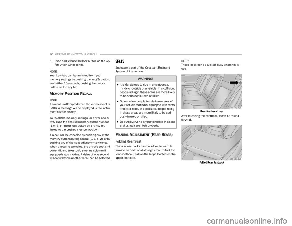
The rear seatbacks can be folded forward to
provide an additional storage area. To fold the
rear seatback, pull on the loops located on the
upper seatback. NOTE:
These loops can be tucked away when not in
use.
Rear Seatback Loop
After releasing the seatback, it can be folded
forward.
Folded Rear Seatback
WARNING!
It is dangerous to ride in a cargo area,
inside or outside of a vehicle. In a collision,
people riding in these areas are more likely
to be seriously injured or killed.
Do not allow people to ride in any area of
your vehicle that is not equipped with seats
and seat belts. In a collision, people riding
in these areas are more likely to be seri -
ously injured or killed.
Be sure everyone in your vehicle is in a seat
and using a seat belt properly.
20_LX_OM_EN_USC_t.book Page 30
Page 35 of 328
GETTING TO KNOW YOUR VEHICLE33
seat position is greater than or equal to
2.7 inches (67.7 mm) forward of the rear
stop. The seat will return to its previously set
position when you place the vehicle’s ignition
in the ACC or RUN position.
The Easy Entry/Easy Exit feature is disabled
when the driver seat position is less than
0.9 of an inch (22.7 mm) forward of the rear
stop. At this position, there is no benefit to
the driver by moving the seat for Easy Exit or
Easy Entry.
Each stored memory setting will have an
associated Easy Entry and Easy Exit position.
NOTE:
The Easy Entry/Exit feature is not enabled when
the vehicle is delivered from the factory. The
Easy Entry/Exit feature is enabled (or later
disabled) through the programmable features
in the Uconnect system. Refer to “Uconnect
Settings” in “Multimedia”.
HEATED SEATS — IF EQUIPPED
On some models, the front and rear seats may
be equipped with heaters located in the seat
cushions and seat backs.
Front Heated Seats
The front heated seat control buttons are
located within the climate or controls screen of
the touchscreen.
You can choose from HI, LO, or OFF heat
settings. The indicator arrows in touchscreen
buttons indicate the level of heat in use. Two
indicator arrows will illuminate for HI, and one for LO. Turning the heating elements off will
return the user to the radio screen.
Press the heated seat button once to turn
the HI setting on.
Press the heated seat button a second
time to turn the LO setting on.
Press the heated seat button a third time
to turn the heating elements off.
If the HI-level setting is selected, the system will
automatically switch to LO-level after
approximately 60 minutes of continuous
operation. At that time, the display will change
from HI to LO, indicating the change. The
LO-level setting will turn off automatically after
approximately 45 minutes.
NOTE:
Once a heat setting is selected, heat will be
felt within two to five minutes.
The engine must be running for the heated
seats to operate.
WARNING!
Persons who are unable to feel pain to the
skin because of advanced age, chronic
illness, diabetes, spinal cord injury, medica -
tion, alcohol use, exhaustion or other phys -
ical condition must exercise care when
using the seat heater. It may cause burns
even at low temperatures, especially if
used for long periods of time.
Do not place anything on the seat or seat -
back that insulates against heat, such as a
blanket or cushion. This may cause the seat
heater to overheat. Sitting in a seat that has
been overheated could cause serious
burns due to the increased surface
temperature of the seat.
2
20_LX_OM_EN_USC_t.book Page 33
Page 37 of 328
GETTING TO KNOW YOUR VEHICLE35
(Continued)
FRONT VENTILATED SEATS — IF
E
QUIPPED
Located in the seat cushion and seat back are
fans that draw the air from the passenger
compartment and move air through fine
perforations in the seat cover to help keep the
driver and front passenger cooler in higher
ambient temperatures. The fans operate at
two speeds, HI and LO.
The front ventilated seats control buttons are
located within the Uconnect system. You can
gain access to the control buttons through the
climate screen or the controls screen.
Press the ventilated seat button once to
choose HI.
Press the ventilated seat button a second
time to choose LO.
Press the ventilated seat button a third
time to turn the ventilated seat off.
NOTE:
The engine must be running for the ventilated
seats to operate. Vehicles Equipped With Remote Start
On models that are equipped with remote start,
the ventilated seats can be programmed to
come on during a remote start.
This feature can be programmed through the
Uconnect system. Refer to “Uconnect Settings”
in “Multimedia” for further information.
HEAD RESTRAINTS
Head restraints are designed to reduce the risk
of injury by restricting head movement in the
event of a rear impact. Head restraints should
be adjusted so that the top of the head restraint
is located above the top of your ear.
NOTE:
Do not reverse the head restraints (making the
rear of the head restraint face forward) in an
attempt to gain additional clearance to the back
of your head.
REACTIVE HEAD RESTRAINTS — FRONT
S
EATS
The front driver and passenger seats are
equipped with Reactive Head Restraints (RHR).
In the event of a rear impact, the RHR will
automatically extend forward minimizing the
gap between the back of the occupant’s head
and the RHR.
The RHR will automatically return to their
normal position following a rear impact. If the
RHR do not return to their normal position, see
an authorized dealer immediately.WARNING!
All occupants, including the driver, should
not operate a vehicle or sit in a vehicle’s
seat until the head restraints are placed in
their proper positions in order to minimize
the risk of neck injury in the event of a
crash.
Head restraints should never be adjusted
while the vehicle is in motion. Driving a
vehicle with the head restraints improperly
adjusted or removed could cause serious
injury or death in the event of a collision.
WARNING! (Continued)
2
20_LX_OM_EN_USC_t.book Page 35
Page 42 of 328

40GETTING TO KNOW YOUR VEHICLE
OUTSIDE MIRRORS WITH TURN SIGNAL
A
ND APPROACH LIGHTING — IF
E
QUIPPED
Driver and passenger outside mirrors with turn
signal and approach lighting contain four LEDs,
which are located in the upper outer corner of
each mirror.
Three of the LEDs are turn signal indicators,
which flash with the corresponding turn signal
lights in the front and rear of the vehicle.
Turning on the Hazard Warning flashers will also
activate these LEDs.
The fourth LED supplies illuminated entry
lighting, which turns on in both mirrors when
you use the remote keyless entry key fob or
open any door. This LED shines outward to
illuminate the front and rear door handles. It
also shines downward to illuminate the area in
front of the doors.
The illuminated entry lighting fades to off after
about 30 seconds or it will fade to off
immediately once the ignition is placed into the
ON/RUN position. NOTE:
The approach lighting will not function when the
gear selector is moved out of the PARK position.POWER MIRRORS
The power mirror controls are located on the
driver's door trim panel.
Power Mirror Control
The power mirror controls consist of mirror
select buttons and a four-way mirror control
switch. To adjust a mirror, push either the L
(left) or R (right) button to select the mirror that
you want to adjust. NOTE:
A light in the select button will illuminate indi
-
cating the mirror is activated and can be
adjusted.
Using the mirror control switch, push on any of
the four arrows for the direction that you want
the mirror to move.
Power mirror preselected positions can be
controlled by the optional Memory Settings
Feature. Refer to “Driver Memory Settings” in
this chapter for further information.
POWER FOLDING OUTSIDE MIRRORS —
I
F EQUIPPED
If equipped with power folding mirrors, they can
be electrically folded rearward and unfolded
into the drive position.
The switch for the power folding mirrors is
located between the power mirror switches
L (left) and R (right). Push the switch once and
the mirrors will fold in, pushing the switch a
second time will return the mirrors to the
normal driving position.
If the mirror is manually folded after electrically
cycled, a potential extra button push is required
to get the mirrors back to the drive position.
1 — Mirror Direction Control
2 — Right Mirror Selection
3 — Left Mirror Selection
20_LX_OM_EN_USC_t.book Page 40
Page 49 of 328
GETTING TO KNOW YOUR VEHICLE47
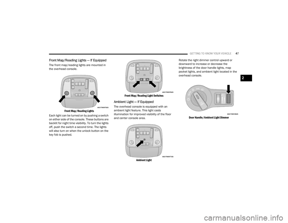
Front Map/Reading Lights — If Equipped
The front map/reading lights are mounted in
the overhead console.
Front Map/Reading Lights
Each light can be turned on by pushing a switch
on either side of the console. These buttons are
backlit for night time visibility. To turn the lights
off, push the switch a second time. The lights
will also turn on when the unlock button on the
key fob is pushed.
Front Map/Reading Light Switches
Ambient Light — If Equipped
The overhead console is equipped with an
ambient light feature. This light casts
illumination for improved visibility of the floor
and center console area.
Ambient Light
Rotate the right dimmer control upward or
downward to increase or decrease the
brightness of the door handle lights, map
pocket lights, and ambient light located in the
overhead console.
Door Handle/Ambient Light Dimmer
2
20_LX_OM_EN_USC_t.book Page 47
Page 54 of 328
52GETTING TO KNOW YOUR VEHICLE
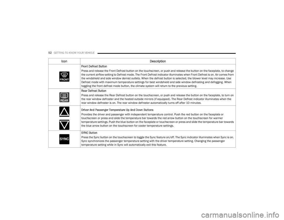
Front Defrost Button
Press and release the Front Defrost button on the touchscreen, or push and release the button on the faceplate, to change
the current airflow setting to Defrost mode. The Front Defrost indicator illuminates when Front Defrost is on. Air comes from
the windshield and side window demist outlets. When the defrost button is selected, the blower level may increase. Use
Defrost mode with maximum temperature settings for best windshield and side window defrosting and defogging. When
toggling the front defrost mode button, the climate system will return to the previous setting.
Rear Defrost Button
Press and release the Rear Defrost button on the touchscreen, or push and release the button on the faceplate, to turn on
the rear window defroster and the heated outside mirrors (if equipped). The Rear Defrost indicator illuminates when the
rear window defroster is on. The rear window defroster automatically turns off after 10 minutes.
Driver And Passenger Temperature Up And Down Buttons
Provides the driver and passenger with independent temperature control. Push the red button on the faceplate or
touchscreen or press and slide the temperature bar towards the red arrow button on the touchscreen for warmer
temperature settings. Push the blue button on the faceplate or touchscreen or press and slide the temperature bar towards
the blue arrow button on the touchscreen for cooler temperature settings.
SYNC Button
Press the Sync button on the touchscreen to toggle the Sync feature on/off. The Sync indicator illuminates when Sync is on.
Sync synchronizes the passenger temperature setting with the driver temperature setting. Changing the passenger
temperature setting while in Sync will automatically exit this feature.
Icon Description
20_LX_OM_EN_USC_t.book Page 52