2020 AUDI A3 warning light
[x] Cancel search: warning lightPage 4 of 400

Table of contents
About this Owner's Manual......
SUMIMALY: ; « ss6% : osen ss sean cs poe s
QC CCeS Skis: si esis a 6 ores os ewe
Controls ataglance..................
Indicator lights overview...........0.
Display and operation............
Instrument cluster...............
Instrument cluster overview...........
Coolant temperature display...........
Tachometer.......... 0.0 eee eee eee
Power iiet@l ss « + wes + s wees 2 x ews 2 ae
Odometer icc oo sisiecs a wrens eo ooarae eo were
Outside temperature display...........
Multifunction steering wheel plus......
Multifunction steering wheel..........
Vehicle functions. ............000 000s
Starting and driving.............
Opening and closing.............
Central locking 2.2% ieee seven a eevee
Luggage compartment lid.............
Child safety lock... 0... 0... cece eee ee
Power windows..............2000005
Panoramic glass TOOf sis s « sayoe « x eoven xs
Power top........... 0. cece eee eee
Automatic power top.................
Wind deflector sicavi x 0 snare a 0 wesc a 0 acaven
Power top emergency operation........
Lights and Vision.................
Exterior lighting...................4.
Interior Ughtingcs « ¢ cean a cas cs ews 5
VISIONS « & comes oo man a 8 eee a a oa 3 oe
Windshield wipers...................
Digital compass.............0.-00 00
PrOntsS@ats = wise s x esven = ¢ eee + & ete os
Head restraimtst. +. coms + 0 anseans 4 2 omamm © # »
Steering wheel............00 2. eee ee
Stowing and using...............
Power sources ......... 00-00 e eee eaee
StOrinG’: « e meme =e sees + Sees Gy ee & Ee
10
14 14 14
15
15
16 17 17 17
20
21
25
25
25 31 33 33 35
36 36 39 39
43
43
46
47
49
52
54
54
54
56 58 59 59 59
Luggage compartment ...............
Roof rack... eee eee
MV APEC OUE 05 3 3 aise ¥ & maseen @ owe
Climate control system...............
Steering wheel heating.............-.
Auxiliary climate control.............-
Fluids in the A/C system. ...........-.
DFIVIFIG:: « yeas os « wow o ¢ Rome se RED oc ow
Starting the vehicle..................
Electromechanical parking brake.......
Releasing the parking lock using the
emergency release............2..000.
Special driving situations..............
Driving dynamic..................
Audi drive'select:, .c.icisiseicascnaene
SUSPONSIOM ac « 2 covsces so cmswsm oo soso oo cee
SEOORIIAG » sinsoes ue vanes a» wisenge ou upnenie & ¥ ote
All wheel drive (quattro)..............
Electronic Stabilization Control.........
High-voltage system.............
General information.................
Charging the high-voltage battery......
Charging at public charging stations....
Charging the battery with the Audi
ChargingsySteM « wsccuc x x sewers a w anaes vv oe
Audi e-tron compact charging system...
Indicator lights and messages.........
Emergency releases. & iseiis 6 + wae w 6 wos
Trailer towing....................
Driving with atrailer.................
Driver assistance.................
Assist systems...................
Speed warning system..............--
Cruise control system............0005
Lap timer eens so cong s pees ss ees oo eee
Audi adaptive cruise control...........
Audi presense............-.002-000-
60
63
65
65
68 68 69
FE 71 73
78
83 85
87
88 89
SI 91
92.
92
93 93
96 96 97
100
Page 12 of 400

Quick access
Indicator lights overview
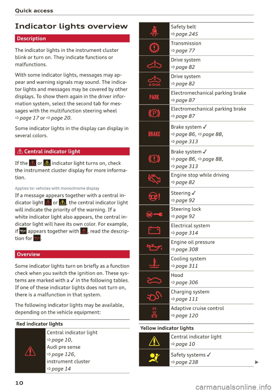
The indicator lights in the instrument cluster
blink or turn on. They indicate functions or
malfunctions.
With some indicator lights, messages may ap-
pear and warning signals may sound. The indica-
tor lights and messages may be covered by other
displays. To show them again in the driver infor-
mation system, select the second tab for mes-
sages with the multifunction steering wheel
=> page 17 or > page 20.
Some indicator lights in the display can display in
several colors.
MMe O eel em lis
If the wa or MN indicator light turns on, check
the instrument cluster display for more informa-
tion.
Applies to: vehicles with monochrome display
If a message appears together with a central in-
dicator light A\ or A the central indicator light
will indicate the priority of the warning. Ifa
white indicator light also appears, the central in-
dicator light will have its own color. For example,
it appears together with Bw read the descrip-
tion for &.
Some indicator lights turn on briefly as a function
check when you switch the ignition on. These sys-
tems are marked with a V in the following tables.
If one of these indicator lights does not turn on,
there is a malfunction in that system.
The following indicator lights may be available,
depending on the vehicle equipment:
Red indicator lights
Central indicator light
=> page 10,
Audi pre sense
=> page 126,
instrument cluster
=> page 14
10
Safety belt
=> page 245
Transmission
> page 77
Drive system
=> page 82
Drive system
=> page 82
Electromechanical parking brake
=> page 87
Electromechanical parking brake
=> page 87
Brake system ¥
=> page 86, > page 88,
=> page 313
Brake system ¥
=> page 86, > page 88,
> page 313
Engine stop while driving
=> page 82
Steering ¥
=> page 92
Steering lock
=> page 92
Electrical system
=> page 314
Engine oil pressure
=> page 308
Cooling system
=> page 311
Hood
=> page 306
Charging system
> page 111
Adaptive cruise control
=> page 120
Yellow indicator lights
Central indicator light
=> page 10
Safety systems ¥
=> page 238
Page 14 of 400

Quick access
Active lane assist
=> page 129
pre sense
=>page 128
Other indicator lights
Start/Stop system
=> page 83
Electric drive ready mode
=> page 79
Charging system
=> page 111
Turn signals
=> page 44, > page 45
Cruise control system
=>page 116
Cruise control system
=>page
116
Adaptive cruise control
=> page 120
Adaptive cruise control
=> page 120
Adaptive cruise control
=> page 120
Adaptive cruise control
=> page 121
Active lane assist
=> page 129
High beams
=> page 44
High beam assistant
=> page 44
Drive system
=> page 82
Electromechanical parking brake
=> page 88
Electromechanical parking brake
Fe ove ae
Electromechanical parking brake
=> page 88,
12
Hill hold assist
=> page 88
Start/Stop system
=> page 83
Start/Stop system
=> page 83
Convenience key
=> page 73
Electric drive ready mode
=> page 79
Combustion engine
=> page 79
Plug-in-hybrid modes
=> page 79
Plug-in-hybrid modes
=> page 79
Charging system
=> page 111
Charging system
=> page 111
Tank system
=> page 302
Park assist
=> page 140
Park assist
=> page 140
High beam assistant
=> page 44
Speed warning system
=>page 115
Speed warning system
=>page 115
Cruise control system
>page 116
Cruise control system
>page 116
Side assist
=>page 135
Adaptive cruise control
=> page 121
Page 17 of 400

8V2012721BK
Instrument cluster
SSGOAM’ sx cscsone ov cxexens @ a aomnees vo s8sue 75
— Audi drive select mode ......... 91
ZA WARNING
Applies to: vehicles with Audi virtual cockpit
If there is a severe malfunction in the instru-
ment cluster, the display may turn off. The wa
indicator light may also turn on. Stop the ve-
hicle safely. See an authorized Audi dealer or
authorized Audi Service Facility for assistance.
@ Tips
— The following pages will primarily show il-
lustrations of the multi-color analog instru-
ment cluster*. The display and/or position
of the element shown may vary in mono-
chrome instrument clusters or in the Audi
virtual cockpit*.
— You can select the units used for tempera-
ture, speed, and other measurements in the
Infotainment system > page 230.
— Speeds are displayed in mph (miles per
hour) or km/h (kilometers per hour).
— If there is a malfunction in the instrument
cluster, DEF will appear in the trip odometer
display. Have the malfunction corrected as
soon as possible.
— Depending on vehicle equipment, the in-
strument illumination (needles and gauges)
may turn on when the lights are off and the
ignition is switched on. The illumination for
the gauges reduces automatically and even-
tually turns off as brightness outside in-
creases. This function reminds the driver to
turn the low beams on at the appropriate
time.
Coolant temperature
display
Applies to: vehicles with a coolant temperature indicator
The coolant temperature display @) > page 14
only functions when the ignition is switched on.
To reduce the risk of engine damage, please ob-
serve the following notes about the temperature
ranges.
Cold range
If only the LEDs at the bottom of the gauge turn
on, the engine has not reached operating tem-
perature yet. Avoid high engine speeds, full accel-
erating and heavy engine loads.
Normal range
The engine has reached its operating tempera-
ture once the LEDs up to the center of the gauge
turn on. If the || indicator light in the instru-
ment cluster display turns on, the coolant tem-
perature is too high > page 311.
@) Note
— Auxiliary headlights and other accessories in
front of the air intake impair the cooling ef-
fect of the coolant. This increases the risk of
the engine overheating during high outside
temperatures and heavy engine load.
—The front spoiler also helps to distribute
cooling air correctly while driving. If the
spoiler is damaged, the cooling effect will
be impaired and the risk of the engine over-
heating will increase. See an authorized
Audi dealer or authorized Audi Service Fa-
cility for assistance.
Tachometer
The tachometer (2) > page 14 displays the engine
speed in revolutions per minute (RPM). The be-
ginning of the red zone in the tachometer indi-
cates the maximum permissible engine speed for
all gears once the engine has been broken in and
when it is warm. Before reaching the red zone,
you should shift into the next higher gear, choose
the "D" or "S" selector lever position, or remove
your foot from the accelerator pedal.
Displaying the tachometer
Applies to: vehicles with plug-in hybrid drive
> Open the first vehicle functions tab using the
<1/D button on the multifunction steering
wheel.
> Applies to: vehicles with analog instrument
cluster: Turn the left thumbwheel on the multi-
function steering wheel until the Tachometer
appears in the instrument cluster.
15
>
Page 19 of 400

8V2012721BK
Instrument cluster
combustion engine for a brief peri-
od of time
Odometer
B8U-0340
8:20™
3/3/2016
Fig. 7 Instrument cluster: odometer
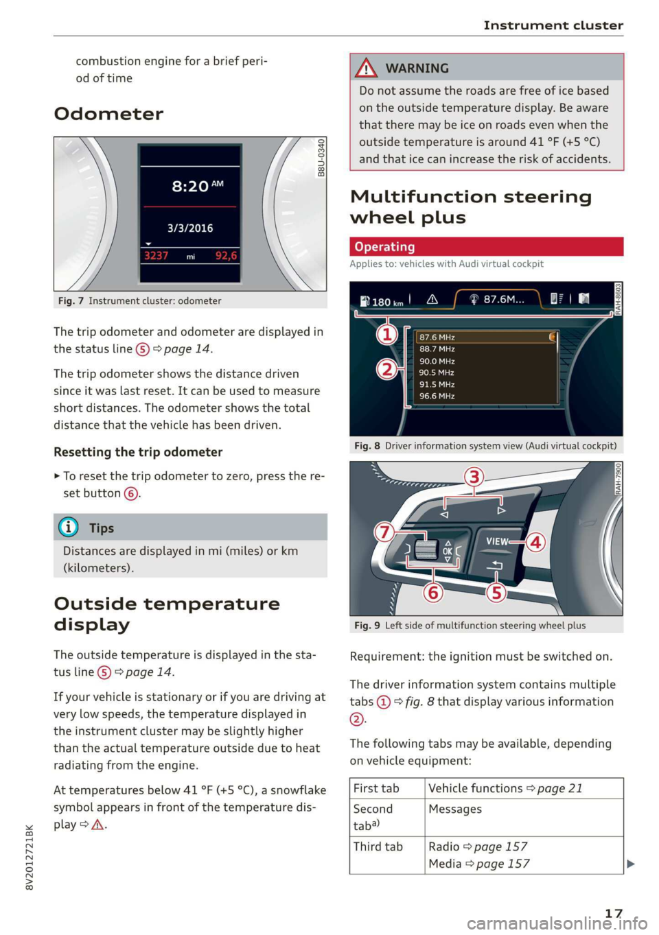
The trip odometer and odometer are displayed in
the status line ©) > page 14.
The trip odometer shows the distance driven
since it was last reset. It can be used to measure
short distances. The odometer shows the total
distance that the vehicle has been driven.
Resetting the trip odometer
> To reset the trip odometer to zero, press the re-
set button ©.
@ Tips
Distances are displayed in mi (miles) or km
(kilometers).
Outside temperature
display
The outside temperature is displayed in the sta-
tus line ©) > page 14.
If your vehicle is stationary or if you are driving at
very low speeds, the temperature displayed in
the instrument cluster may be slightly higher
than the actual temperature outside due to heat
radiating from the engine.
At temperatures below 41 °F (+5 °C), a snowflake
symbol appears in front of the temperature dis-
play > A\.
ZA WARNING
Do not assume the roads are free of ice based
on the outside temperature display. Be aware
that there may be ice on roads even when the
outside temperature is around 41 °F (+5 °C)
and that ice can increase the risk of accidents.
Multifunction steering
wheel plus
Applies to: vehicles with Audi virtual cockpit
B180im! A
Fig. 8 Driver information system view (Audi virtual cockpit)
Fig. 9 Left side of multifunction steering wheel plus
Requirement: the ignition must be switched on.
The driver information system contains multiple
tabs @ © fig. 8 that display various information
®.
The following tabs may be available, depending
on vehicle equipment:
First tab Vehicle functions > page 21
Second Messages
tab?
Third tab Radio > page 157
Media > page 157
17
Page 31 of 400

8V2012721BK
Opening and closing
ZA WARNING
Read and following all warnings > A\ in De-
scription on page 25.
@ Tips
If your vehicle is left standing for a long peri-
od of time, note the following:
— The proximity sensor switches off after a
few days to save energy. You then have to
pull once on the door handle to unlock the
vehicle and a second time to open it.
—To prevent the vehicle battery from dis-
charging, the energy management gradual-
ly switches off convenience functions that
are not needed. You then may no longer be
able to unlock your vehicle with the sensors.
(eye eked Reauuia
Fig. 22 Driver's door: central locking switch
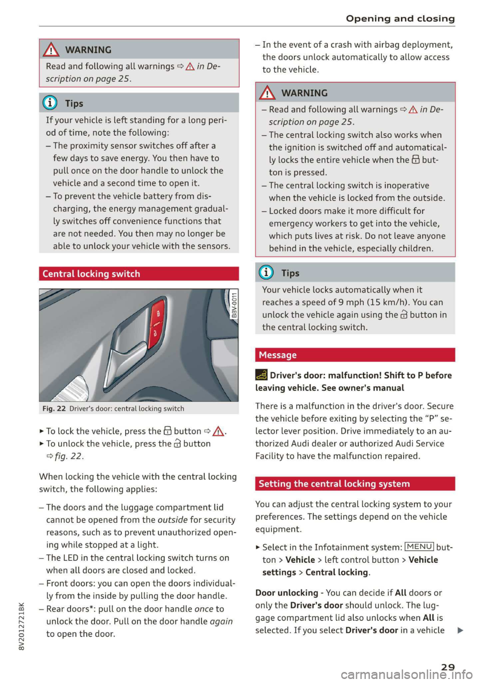
> To lock the vehicle, press the & button > A\.
> To unlock the vehicle, press the G button
fig. 22.
When locking the vehicle with the central locking
switch,
the following applies:
— The doors and the luggage compartment lid
cannot be opened from the outside for security
reasons, such as to prevent unauthorized open-
ing while stopped at a light.
— The LED in the central locking switch turns on
when all doors are closed and locked.
— Front doors: you can open the doors individual-
ly from the inside by pulling the door handle.
— Rear doors*: pull on the door handle once to
unlock the door. Pull on the door handle again
to open the door.
— In the event of a crash with airbag deployment,
the doors unlock automatically to allow access
to the vehicle.
ZA WARNING
— Read and following all warnings > A in De-
scription on page 25.
— The central locking switch also works when
the ignition is switched off and automatical-
ly locks the entire vehicle when the & but-
ton is pressed.
—The central locking switch is inoperative
when the vehicle is locked from the outside.
— Locked doors make it more difficult for
emergency workers to get into the vehicle,
which puts lives at risk. Do not leave anyone
behind in the vehicle, especially children.
@ Tips
Your vehicle locks automatically when it
reaches a speed of 9 mph (15 km/h). You can
unlock the vehicle again using the @ button in
the central locking switch.
2B Driver's door: malfunction! Shift to P before
leaving vehicle. See owner's manual
There is a malfunction in the driver's door. Secure
the vehicle before exiting by selecting the “P” se-
lector lever position. Drive immediately to an au-
thorized Audi dealer or authorized Audi Service
Facility to have the malfunction repaired.
Setting the central locking system
You can adjust the central locking system to your
preferences. The settings depend on the vehicle
equipment.
> Select in the Infotainment system: [MENU] but-
ton > Vehicle > left control button > Vehicle
settings > Central locking.
Door unlocking - You can decide if All doors or
only the Driver's door should unlock. The lug-
gage compartment lid also unlocks when All is
selected. If you select Driver's door inavehicle >
29
Page 35 of 400

8V2012721BK
Opening and closing
Child safety lock
Applies to: vehicles with mechanical child safety locks
The child safety lock prevents the rear doors
from being opened from the inside and the rear
power windows from being operated.
B8U-0320
Fig. 31 Rear door: manual child safety lock
> To activate or deactivate the child safety lock
for the power window switches in the rear
doors, press the 4&3 switch in the driver's door
=> fig. 30. The indicator light in the button turns
on/blinks.
> To activate or deactivate the manual child safe-
ty lock for the rear door handle, open the rear
door and turn the key switch either in the direc-
tion of the arrow (to activate) or opposite the
direction of the arrow (to deactivate) using with
the vehicle key > fig. 31. This will disable the
function of the rear door handle.
> Make sure the child safety lock is working by
checking the function on the rear power win-
dow switch and door handle.
Message in the instrument cluster display
Childproof catch: malfunction! Please con-
tact Service
There is a malfunction in the child safety lock.
Press the GQ button again.
If the message stays on, drive immediately to an
authorized Audi dealer or authorized Audi Service
Facility to have the malfunction repaired.
, WARNING
— If you leave the vehicle, switch the ignition
off and take the vehicle key with you. This
applies particularly when children remain in
the vehicle. Otherwise children could start
the engine or operate electrical equipment
(such as power windows), which increases
the risk of an accident.
—A malfunction in the child safety lock could
allow the rear doors to be opened from the
inside, which increases the risk of an acci-
dent.
Power windows
The driver can control all power windows.
rey q 2
Z| 2
a
Fig. 32 Driver's door: power window controls
All power window switches are equipped with a
two-stage function:
Opening and closing the windows
> To open or close the window completely, press
the switch down or pull the switch up briefly to
the second level. The operation will stop if the
switch is pressed or pulled again.
> To select a position in between opened and
closed, press or pull the switch to the first level
until
the desired window position is reached.
33
>
Page 39 of 400

8V2012721BK
Power top
sure the rear passengers keep enough dis-
tance from the power top to reduce the risk
of injury.
— Visibility to the rear is limited when operat-
ing the power top. Avoid operating the top
while driving in reverse.
@) Note
— To prevent damage to the power top:
— do not store any objects in the power top
storage compartment.
— make sure there is enough space above
the vehicle when opening or closing the
power top.
—To reduce the risk of damage, make sure
there are no sensitive objects in the power
top storage compartment's range of mo-
tion.
G) Tips
— To prevent the vehicle battery from draining
unnecessarily, do not open or close the pow-
er top repeatedly when the engine is switch-
ed off.
—A message will appear in the instrument
cluster if there is a malfunction in the power
top > page 38.
— The power top can also be operated manual-
ly temporarily if there is a malfunction
=> page 39, Power top emergency opera-
tion. An authorized Audi dealer or author-
ized Audi Service Facility should diagnose
and correct the cause of the malfunction as
soon as possible.
— If the vehicle is parked with the power top
open, the vehicle interior is not protected
from damaging weather or unauthorized ac-
cess. Lock any items you leave behind in the
luggage compartment. Close the power top
before leaving the vehicle.
— The side windows automatically lower
slightly when opening or closing the power
top.
Power top convenience opening and closing
Applies to: vehicles with power top
B8V-0009 @)
"A
4
Fig. 35 Turning the key to open and close
Convenience opening with the driver door
lock
> Turn the key once in the driver door lock to the
opening position @).
> Turn the key to the opening position again
within two seconds and hold it there until the
power top opens completely.
Convenience closing with the driver door lock
> Turn the key once in the driver door lock to the
closing position @).
> Turn the key to the closing position again with-
in two seconds and hold it there until the pow-
er top closes completely.
Releasing the key stops the opening or closing
process immediately.
ZA\ WARNING
Read and follow the important safety precau-
tions > A\ in Opening and closing the power
top on page 36.
37