2019 TOYOTA SUPRA ESP
[x] Cancel search: ESPPage 113 of 456
113
3
Supra Owner's Manual3-1. CONTROLS
CONTROLS
Only certain ISOFIX child restraints
may be used in the seats intended
for this purpose. The corresponding
size class and size category are
denoted by a letter or ISO refer-
ence on a plate on the child seat.
For information about which child
restraint systems can be used on
the seats in question and if the child
restraint systems are suitable for or
comply with ISOFIX, see: seats that
are suitable for child restraint sys-
tems, see page 115.Not for Australia/New Zealand:
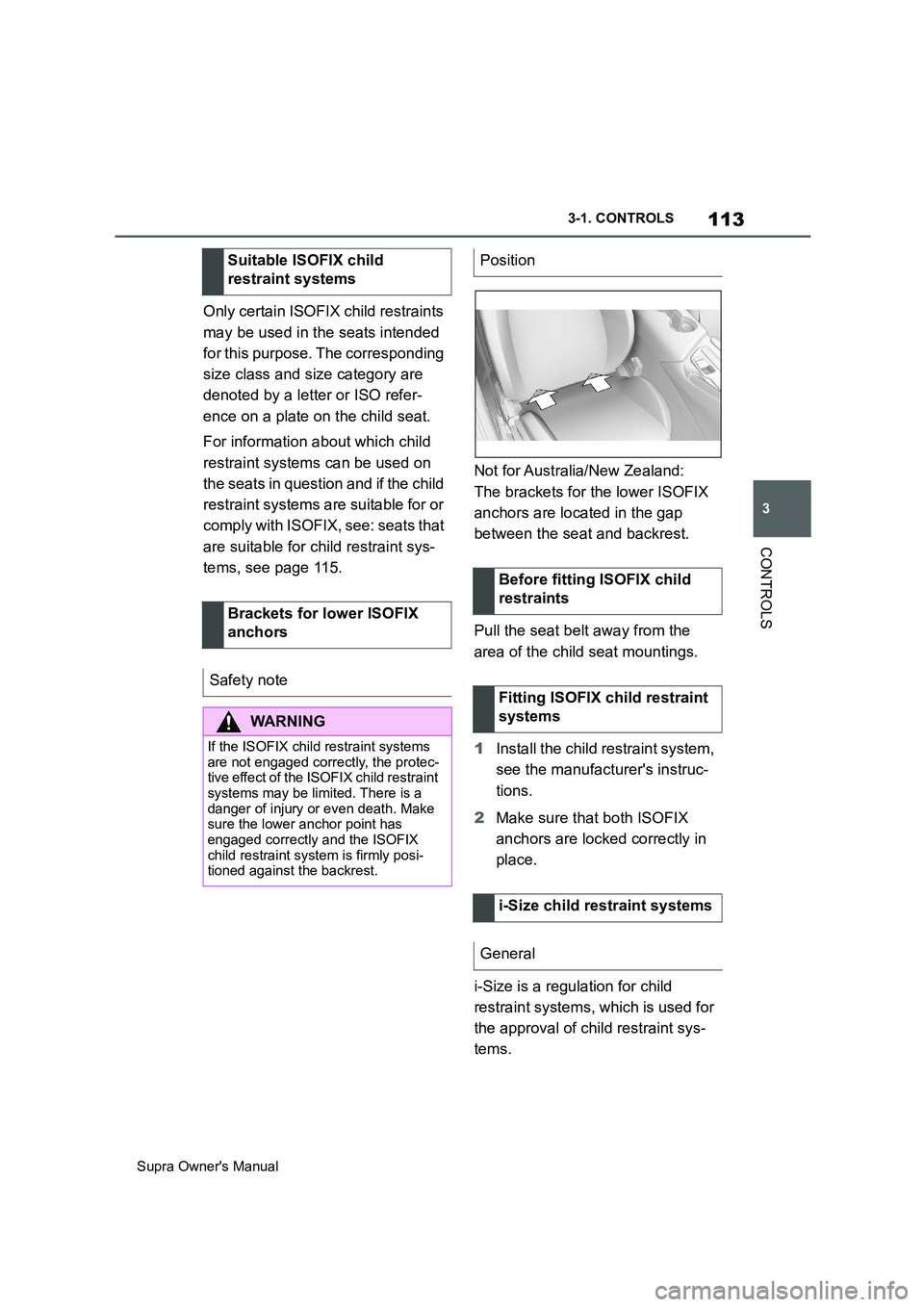
The brackets for the lower ISOFIX
anchors are located in the gap
between the seat and backrest.
Pull the seat belt away from the
area of the child seat mountings.
1Install the child restraint system,
see the manufacturer's instruc-
tions.
2Make sure that both ISOFIX
anchors are locked correctly in
place.
i-Size is a regulation for child
restraint systems, which is used for
the approval of child restraint sys-
tems. Suitable ISOFIX child
restraint systems
Brackets for lower ISOFIX
anchors
Safety note
WARNING
If the ISOFIX child restraint systems
are not engaged correctly, the protec-
tive effect of the ISOFIX child restraint
systems may be limited. There is a
danger of injury or even death. Make
sure the lower anchor point has
engaged correctly and the ISOFIX
child restraint system is firmly posi-
tioned against the backrest.
Position
Before fitting ISOFIX child
restraints
Fitting ISOFIX child restraint
systems
i-Size child restraint systems
General
Page 114 of 456

114
Supra Owner's Manual3-1. CONTROLS
There is a mounting point for the
upper retaining strap of ISOFIX
child restraint systems.
1Direction of travel
2Head restraint
3Hook for the upper retaining
strap
4Mounting point/eyelet
5Vehicle floor
6Seat
7Upper retaining strap
SymbolMeaning
If this symbol is seen in
the vehicle, the vehicle
has been approved in
accordance with i-Size.
The symbol shows the
mounts for the system's
lower anchors.
The corresponding sym-
bol shows the mounting
point for the upper retain-
ing strap.
Mounts for the upper ISOFIX
retaining strap
Safety notes
WARNING
If the upper retaining strap is used
incorrectly with the child restraint sys-
tem, the protective effect may be
reduced. There is a danger of injury.
Make sure that the upper retaining
strap is not routed to the upper
attachment strap over sharp edges
and that it is not twisted.
NOTICE
The mounting points for the upper
retaining straps of child restraint sys-
tems are only intended for these
retaining straps. The mounting points
can be damaged if other objects are
attached. There is a danger of dam-
age to property. Only attach child
restraint systems to the upper retain-
ing straps.
Mounting points
SymbolMeaning
The corresponding sym-
bol shows the mounting
point for the upper retain-
ing strap.
Routing the retaining strap
Page 134 of 456
134
Supra Owner's Manual3-1. CONTROLS
This chapter describes all standard,
country-specific and special equip-
ment available for the model series.
It may therefore describe equip-
ment and functions which are not
installed in your vehicle, for exam-
ple on account of the optional
equipment selected or the country
specification. This also applies to
safety-relevant functions and sys-
tems. Please comply with the rele-
vant laws and regulations when
using the corresponding functions
and systems.
Automatic transmission:
Drive-ready state is switched on by
pressing the start/stop button while
the brake pedal is depressed.
Pressing the start/stop button again
switches drive-ready state back off
and standby state, see page 44, is
switched on.The Auto Start/Stop helps you to
save fuel. The system stops the
engine when stationary, for exam-
ple in a traffic jam or at traffic lights.
The drive-ready state remains
switched on. For driving off, the
engine starts automatically.
Each time the engine is started via
the start/stop button, the Auto
Start/Stop is switched to standby.
The function is activated from a
speed of around 5 km/h, approxi-
mately 3 mph.
Depending on selected drive mode,
see page 149, the system is acti-
vated or deactivated automatically.
■Automatic transmission
The engine is automatically shut
down when stationary under the fol-
lowing conditions:
Selector lever in selector lever
position D.
Brake pedal remains pressed
while the vehicle is at a standstill.
Driver's seat belt buckled or
driver's door closed.
Driving
Vehicle equipment
Start/stop button
Principle
Drive-ready state, see
page 44, is switched on
and off by pressing the
start/stop button.
Auto Start/Stop
Principle
General
Stopping the engine
Operating requirements
Page 146 of 456
146
Supra Owner's Manual3-1. CONTROLS
Irrespective of standby state, selec-
tor lever position P is engaged
automatically after approximately
35 minutes.
If there is a fault, it may not be pos-
sible to change the selector lever
position.
Unlock the transmission lockout
electronically if necessary, see
page 147.
Kick-down enables you to achieve
maximum performance.
Press the accelerator pedal down
beyond the regular full-throttle posi-
tion; resistance will be felt.
The gears can be changed manu-
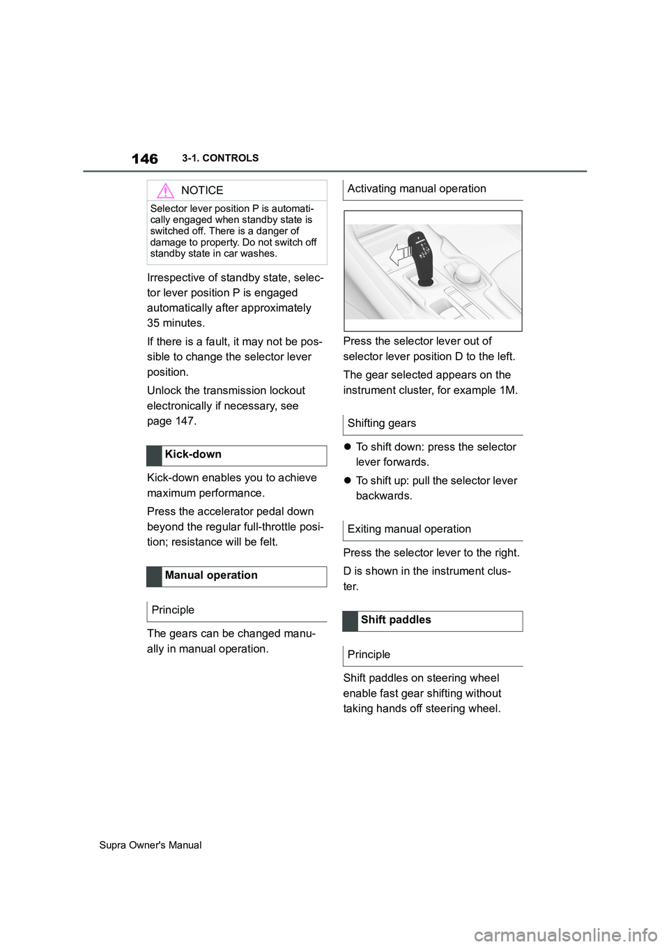
ally in manual operation.Press the selector lever out of
selector lever position D to the left.
The gear selected appears on the
instrument cluster, for example 1M.
To shift down: press the selector
lever forwards.
To shift up: pull the selector lever
backwards.
Press the selector lever to the right.
D is shown in the instrument clus-
ter.
Shift paddles on steering wheel
enable fast gear shifting without
taking hands off steering wheel.
NOTICE
Selector lever position P is automati-
cally engaged when standby state is
switched off. There is a danger of
damage to property. Do not switch off
standby state in car washes.
Kick-down
Manual operation
Principle
Activating manual operation
Shifting gears
Exiting manual operation
Shift paddles
Principle
Page 151 of 456
151
3
Supra Owner's Manual3-1. CONTROLS
CONTROLS
This chapter describes all standard,
country-specific and special equip-
ment available for the model series.
It may therefore describe equip-
ment and functions which are not
installed in your vehicle, for exam-
ple on account of the optional
equipment selected or the country
specification. This also applies to
safety-relevant functions and sys-
tems. Please comply with the rele-
vant laws and regulations when
using the corresponding functions
and systems.
The instrument cluster is a variable
display. When the sport mode
switch is used to change the driving
mode, the instrument cluster dis-
plays change to match the driving
mode.
Changes to the displays in the
instrument cluster can be deacti-
vated via Toyota Supra Command.
The displays in the instrument clus-
ter can sometimes differ from the
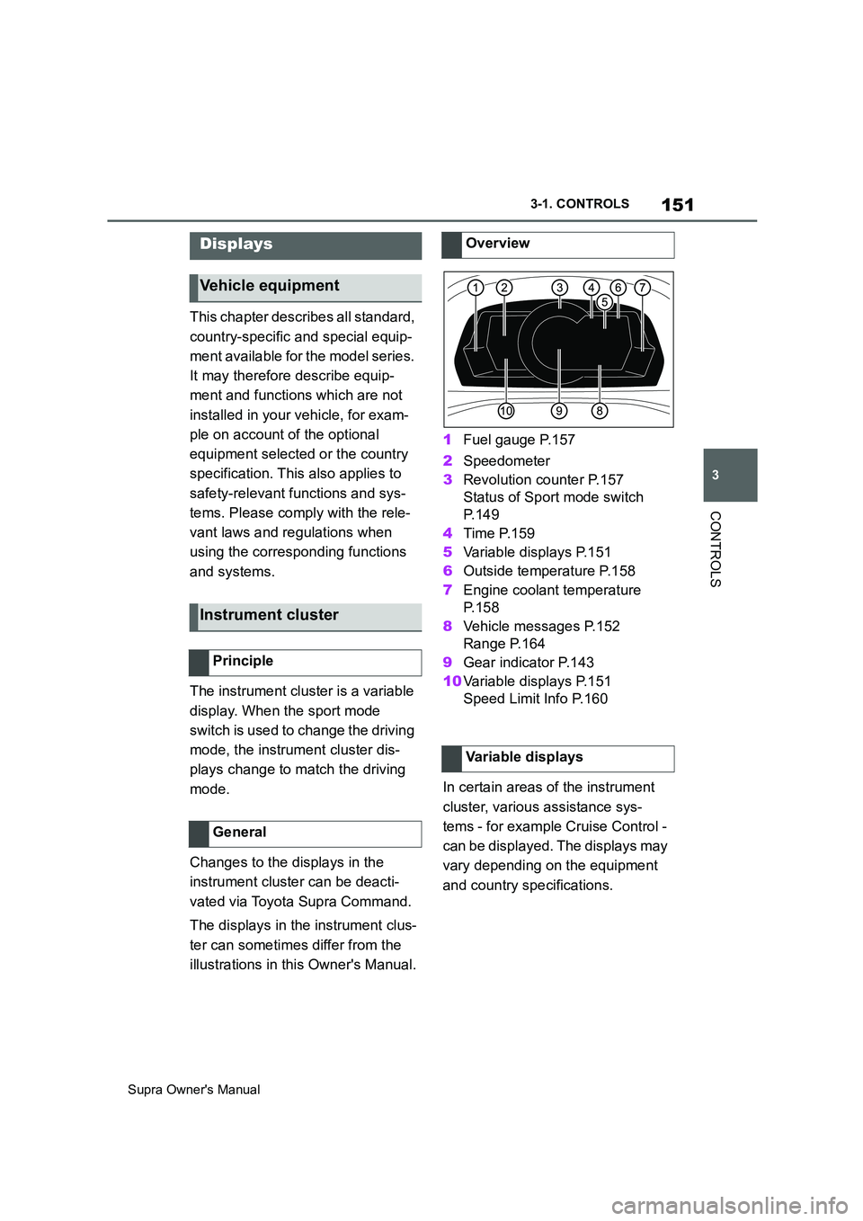
illustrations in this Owner's Manual.1Fuel gauge P.157
2Speedometer
3Revolution counter P.157
Status of Sport mode switch
P. 1 4 9
4Time P.159
5Variable displays P.151
6Outside temperature P.158
7Engine coolant temperature
P. 1 5 8
8Vehicle messages P.152
Range P.164
9Gear indicator P.143
10Variable displays P.151
Speed Limit Info P.160
In certain areas of the instrument
cluster, various assistance sys-
tems - for example Cruise Control -
can be displayed. The displays may
vary depending on the equipment
and country specifications.
Displays
Vehicle equipment
Instrument cluster
Principle
General
Overview
Variable displays
Page 160 of 456

160
Supra Owner's Manual3-1. CONTROLS
The system recommends the most
efficient gear for the current driving
situation.
Depending on the design and the
country specifications, the shift
point indicator is active in manual
mode of the automatic transmis-
sion.
Information on up or down shifting
are displayed in the instrument
cluster.
Speed Limit Info shows the cur-
rently applicable speed limit in the instrument cluster and the Head-Up
Display, as well as additional signs
where applicable, for example in
wet conditions.
The camera in the area of the inte-
rior rear-view mirror detects traffic
signs at the edge of the road as
well as variable overhead signs.
Road signs with additional instruc-
tions, for example restrictions appli-
cable in wet weather, are taken into
account and correlated with infor-
mation in the vehicle, such as the
windscreen wiper signal. The road
sign and corresponding additional
signs are then displayed in the
instrument cluster and the Head-Up
Display, if applicable, or ignored,
depending on the situation. Some
additional signs are taken into
account in the evaluation of the
speed limit, but are not displayed in
the instrument cluster.
The system considers the informa-
tion saved in the navigation system
as applicable and also displays the
speed limits present on unmarked
sections of road.
Overtaking restriction signs and
end of restriction signs that are
Shift point indicator
Principle
General
Automatic transmission: dis-
plays
ExampleDescription
Most efficient gear is
engaged.
Shift to a more efficient
gear.
Speed Limit Info with over-
taking restriction display
Speed Limit Info
Principle
General
Overtaking restriction dis-
play
Principle
Page 161 of 456
161
3
Supra Owner's Manual3-1. CONTROLS
CONTROLS
detected by the camera are indi-
cated by corresponding symbols in
the instrument cluster and, if appli-
cable, the Head-Up Display.
The system considers overtaking
restrictions and ends of restrictions
that are indicated by means of
signs.
Nothing will be displayed in the fol-
lowing situations:
In countries in which no overtak-
ing is primarily shown by road
markings.
On routes without signs.
In the case of railway crossings,
lane markings and other situa-
tions which indicate an overtak-
ing restriction but which are not
signposted to this effect.
Depending on the equipment ver-
sion, an additional symbol with dis-
tance information may also be
displayed to indicate the end of the
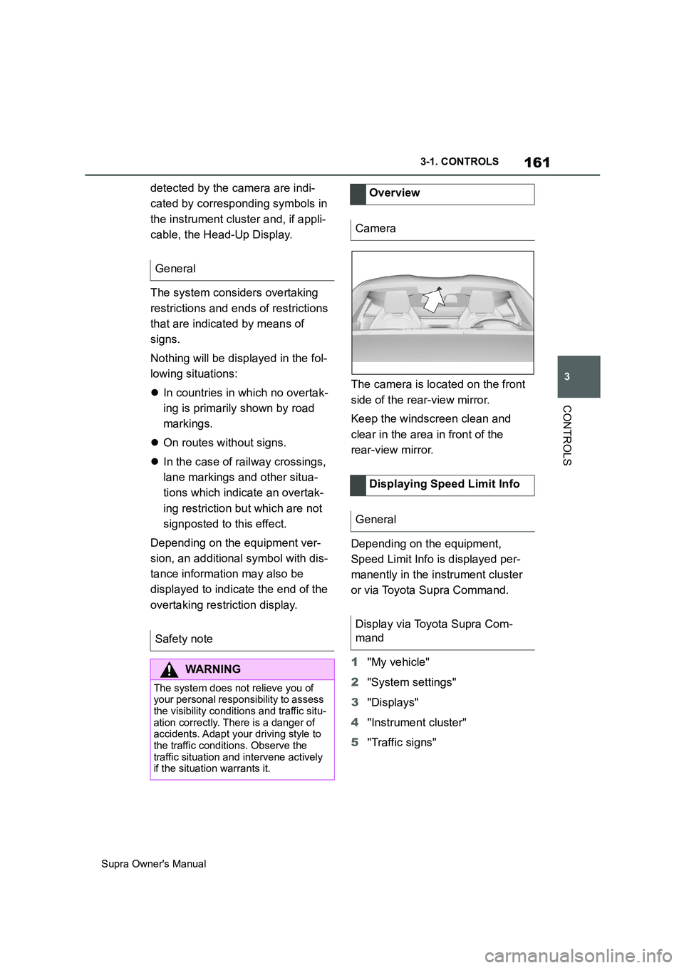
overtaking restriction display.The camera is located on the front
side of the rear-view mirror.
Keep the windscreen clean and
clear in the area in front of the
rear-view mirror.
Depending on the equipment,
Speed Limit Info is displayed per-
manently in the instrument cluster
or via Toyota Supra Command.
1"My vehicle"
2"System settings"
3"Displays"
4"Instrument cluster"
5"Traffic signs" General
Safety note
WARNING
The system does not relieve you of
your personal responsibility to assess
the visibility conditions and traffic situ-
ation correctly. There is a danger of
accidents. Adapt your driving style to
the traffic conditions. Observe the
traffic situation and intervene actively
if the situation warrants it.
Overview
Camera
Displaying Speed Limit Info
General
Display via Toyota Supra Com-
mand
Page 163 of 456
163
3
Supra Owner's Manual3-1. CONTROLS
CONTROLS
the Speed Limit Info display in
the instrument cluster and the
Head-Up Display when the cur-
rently applicable speed limit is
exceeded.
"Show speeding": the speed limit
detected by the Speed Limit Info
is indicated by a mark in the
speedometer in the instrument
cluster.
The function may be restricted and
may display incorrect information in
the following situations, for exam-
ple:
In thick fog, wet conditions or
snow.
If signs are fully or partially
obscured by objects, stickers or
paint.
If the vehicle is too close to the
vehicle ahead.
In the case of bright oncoming
light or strong reflections.
When the windscreen in front of
the rear-view mirror is covered
with condensation, dirt, stickers,
etc.
If the camera has overheated
due to excessively high tempera-
tures and has been temporarily
deactivated.
As a result of incorrect detection
by the camera.
If the speed limits stored in the navigation system or road data
are incorrect.
In the case of speed limits that
depend or the time of day or day
of the week.
In areas not covered by the navi-
gation system.
If there are deviations in relation
to navigation, for example due to
changes in road routing.
In the case of electronic road
signs.
When overtaking buses or trucks
with road sign stickers.
If traffic signs do not correspond
to the standard.
If signs are detected that apply to
a parallel road.
In the case of country-specific
signs or road layouts.
During the camera calibration
process immediately after vehi-
cle delivery.
The display can be operated when
necessary.
Entertainment source.
Current audio source.
Last calls list.
If applicable, the relevant menu is
opened on the Control Display. System limits
Selection lists
Principle