2019 Ram 1500 brake light
[x] Cancel search: brake lightPage 420 of 698

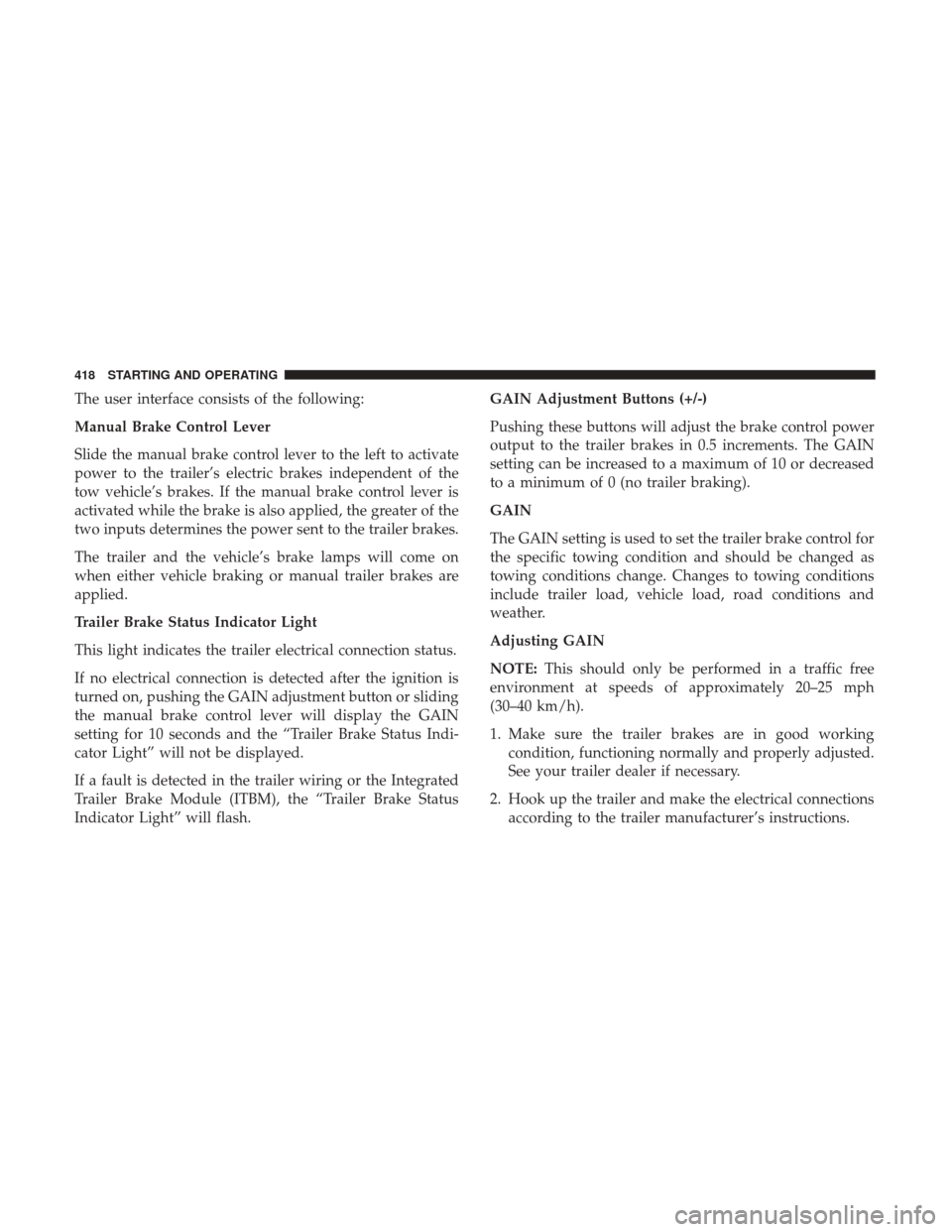
The user interface consists of the following:
Manual Brake Control Lever
Slide the manual brake control lever to the left to activate
power to the trailer’s electric brakes independent of the
tow vehicle’s brakes. If the manual brake control lever is
activated while the brake is also applied, the greater of the
two inputs determines the power sent to the trailer brakes.
The trailer and the vehicle’s brake lamps will come on
when either vehicle braking or manual trailer brakes are
applied.
Trailer Brake Status Indicator Light
This light indicates the trailer electrical connection status.
If no electrical connection is detected after the ignition is
turned on, pushing the GAIN adjustment button or sliding
the manual brake control lever will display the GAIN
setting for 10 seconds and the “Trailer Brake Status Indi-
cator Light” will not be displayed.
If a fault is detected in the trailer wiring or the Integrated
Trailer Brake Module (ITBM), the “Trailer Brake Status
Indicator Light” will flash.GAIN Adjustment Buttons (+/-)
Pushing these buttons will adjust the brake control power
output to the trailer brakes in 0.5 increments. The GAIN
setting can be increased to a maximum of 10 or decreased
to a minimum of 0 (no trailer braking).
GAIN
The GAIN setting is used to set the trailer brake control for
the specific towing condition and should be changed as
towing conditions change. Changes to towing conditions
include trailer load, vehicle load, road conditions and
weather.
Adjusting GAIN
NOTE:
This should only be performed in a traffic free
environment at speeds of approximately 20–25 mph
(30–40 km/h).
1. Make sure the trailer brakes are in good working condition, functioning normally and properly adjusted.
See your trailer dealer if necessary.
2. Hook up the trailer and make the electrical connections according to the trailer manufacturer’s instructions.
418 STARTING AND OPERATING
Page 421 of 698

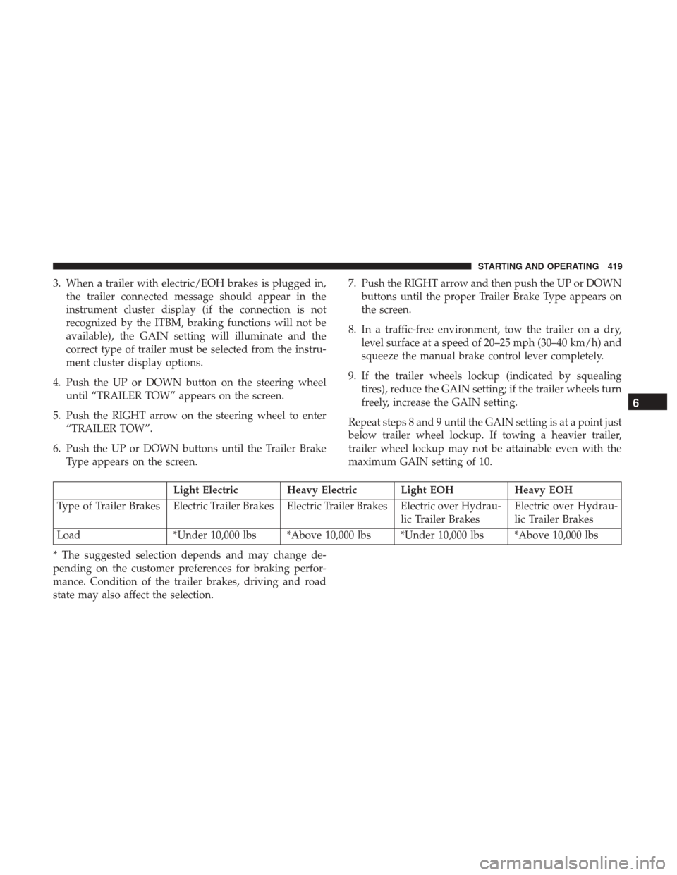
3. When a trailer with electric/EOH brakes is plugged in,the trailer connected message should appear in the
instrument cluster display (if the connection is not
recognized by the ITBM, braking functions will not be
available), the GAIN setting will illuminate and the
correct type of trailer must be selected from the instru-
ment cluster display options.
4. Push the UP or DOWN button on the steering wheel until “TRAILER TOW” appears on the screen.
5. Push the RIGHT arrow on the steering wheel to enter “TRAILER TOW”.
6. Push the UP or DOWN buttons until the Trailer Brake Type appears on the screen. 7. Push the RIGHT arrow and then push the UP or DOWN
buttons until the proper Trailer Brake Type appears on
the screen.
8. In a traffic-free environment, tow the trailer on a dry, level surface at a speed of 20–25 mph (30–40 km/h) and
squeeze the manual brake control lever completely.
9. If the trailer wheels lockup (indicated by squealing tires), reduce the GAIN setting; if the trailer wheels turn
freely, increase the GAIN setting.
Repeat steps 8 and 9 until the GAIN setting is at a point just
below trailer wheel lockup. If towing a heavier trailer,
trailer wheel lockup may not be attainable even with the
maximum GAIN setting of 10.
Light Electric Heavy Electric Light EOH Heavy EOH
Type of Trailer Brakes Electric Trailer Brakes Electric Trailer Brakes Electric over Hydrau- lic Trailer BrakesElectric over Hydrau-
lic Trailer Brakes
Load *Under 10,000 lbs *Above 10,000 lbs *Under 10,000 lbs *Above 10,000 lbs
* The suggested selection depends and may change de-
pending on the customer preferences for braking perfor-
mance. Condition of the trailer brakes, driving and road
state may also affect the selection.
6
STARTING AND OPERATING 419
Page 422 of 698

Display Messages
The trailer brake control interacts with the instrument
cluster display. Display messages, along with a single
chime, will be displayed when a malfunction is determined
in the trailer connection, trailer brake control, or on the
trailer. Refer to “Instrument Cluster Display” in “Getting
To Know Your Instrument Panel” for further information.
WARNING!
Connecting a trailer that is not compatible with the
ITBM system may result in reduced or complete loss of
trailer braking. There may be a increase in stopping
distance or trailer instability which could result in
personal injury.
CAUTION!
Connecting a trailer that is not compatible with the
ITBM system may result in reduced or complete loss of
trailer braking. There may be a increase in stopping
distance or trailer instability which could result in
damage to your vehicle, trailer, or other property.NOTE:
•
An aftermarket controller may be available for use with
trailers with air or electric-over-hydraulic trailer brake
systems. To determine the type of brakes on your trailer
and the availability of controllers, check with your
trailer manufacturer or dealer.
• Removal of the ITBM will cause errors and it may cause
damage to the electrical system and electronic modules
of the vehicle. See your authorized dealer if an aftermar-
ket module is to be installed.
Towing Requirements — Trailer Lights And Wiring
Whenever you pull a trailer, regardless of the trailer size,
stoplights and turn signals on the trailer are required for
motoring safety.
The Trailer Tow Package may include a four- and seven-pin
wiring harness. Use a factory approved trailer harness and
connector.
NOTE: Do not cut or splice wiring into the vehicle’s wiring
harness.
The electrical connections are all complete to the vehicle
but you must mate the harness to a trailer connector. Refer
to the following illustrations.
420 STARTING AND OPERATING
Page 429 of 698

2. Press and hold the brake pedal.
3. Shift the transmission to NEUTRAL. The driver’s doormust be closed (or the driver’s seat belt buckled) so that
the transmission will remain in NEUTRAL when the
brake pedal is released.
NOTE: If vehicle is equipped with air suspension, ensure
the vehicle is set to Normal Ride Height.
4. Using a ballpoint pen or similar object, push and hold the recessed transfer case NEUTRAL (N) button (at the
center of the transfer case switches). The NEUTRAL (N)
indicator light will illuminate, and remain lit, when the
shift to NEUTRAL (N) is complete. After the shift is
completed and the NEUTRAL (N) light stays on, release
the NEUTRAL (N) button.
5. Release the parking brake.
6. Shift the transmission into REVERSE. 7. Release the brake pedal for five seconds and ensure that
there is no vehicle movement.
8. Repeat steps 6 and 7 with the transmission in DRIVE.
9. Shift the transmission to NEUTRAL. Apply the parking brake. Turn OFF the engine. For vehicles with Keyless
Enter-N-Go, push and hold the ENGINE START/STOP
button until the engine shuts off. The transmission will
automatically select PARK when the engine is turned
off.
10. Turn the ignition to the OFF mode.
11. Attach the vehicle to the tow vehicle using a suitable tow bar.
12. Turn the ignition to the ON/RUN mode, but do not start the engine.
13. Release the parking brake.
14. Turn the ignition OFF.
6
STARTING AND OPERATING 427
Page 430 of 698

NOTE:
•Steps 2 and 3 are requirements that must be met before
pushing the NEUTRAL (N) button, and must continue
to be met until the shift has been completed. If any of
these requirements are not met before pushing the
NEUTRAL (N) button or are no longer met during the
shift, the NEUTRAL (N) indicator light will flash con-
tinuously until all requirements are met or until the
NEUTRAL (N) button is released.
• The ignition must be in the ON/RUN mode for a shift to
take place and for the position indicator lights to be
operable. If the ignition is not in the ON/RUN mode, the
shift will not take place and no position indicator lights
will be on or flashing.
• A flashing NEUTRAL (N) position indicator light indi-
cates that shift requirements have not been met.
• If the vehicle is equipped with air suspension, the engine
should be started and left running for a minimum of 60
seconds (with all the doors closed) at least once every 24
hours. This process allows the air suspension to adjust
the vehicle’s ride height to compensate for temperature
effects.Shifting Out Of NEUTRAL (N)
Use the following procedure to prepare your vehicle for
normal usage:
1. Bring the vehicle to a complete stop, leaving it con- nected to the tow vehicle.
2. Press and hold the brake pedal.
3. Start the engine. Apply the parking brake. Shift the transmission into NEUTRAL.
4. Using a ballpoint pen or similar object, push and hold the recessed transfer case NEUTRAL (N) button (at the
center of the transfer case switches).
5. When the NEUTRAL (N) indicator light turns off, release the NEUTRAL (N) button.
6. Turn the engine OFF. The transmission will automati- cally select PARK when the engine is turned off.
7. Release the brake pedal.
8. Disconnect vehicle from the tow vehicle.
9. Press and hold the brake pedal.
10. Start the engine.
11. Release the parking brake.
428 STARTING AND OPERATING
Page 431 of 698

12. Shift the transmission into DRIVE, release the brakepedal, and check that the vehicle operates normally.
NOTE:
• Steps 3 and 4 are requirements that must be met before
pushing the button to shift out of NEUTRAL (N), and
must continue to be met until the shift has been com-
pleted. If any of these requirements are not met before
pushing the button or are no longer met during the shift,
the NEUTRAL (N) indicator light will flash continu-
ously until all requirements are met or until the button is
released.
• The ignition must be in the ON/RUN mode for a shift to
take place and for the position indicator lights to be
operable. If the ignition is not in the ON/RUN mode, the
shift will not take place and no position indicator lights
will be on or flashing.
• A flashing NEUTRAL (N) position indicator light indi-
cates that shift requirements have not been met.DRIVING TIPS
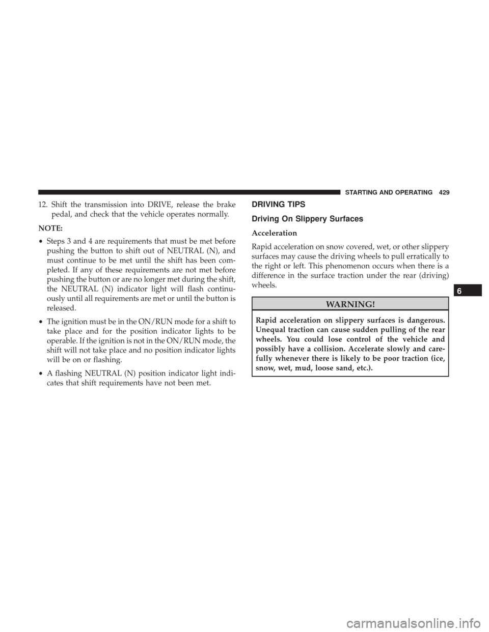
Driving On Slippery Surfaces
Acceleration
Rapid acceleration on snow covered, wet, or other slippery
surfaces may cause the driving wheels to pull erratically to
the right or left. This phenomenon occurs when there is a
difference in the surface traction under the rear (driving)
wheels.
WARNING!
Rapid acceleration on slippery surfaces is dangerous.
Unequal traction can cause sudden pulling of the rear
wheels. You could lose control of the vehicle and
possibly have a collision. Accelerate slowly and care-
fully whenever there is likely to be poor traction (ice,
snow, wet, mud, loose sand, etc.).
6
STARTING AND OPERATING 429
Page 432 of 698

Driving Through Water
Driving through water more than a few inches/centimeters
deep will require extra caution to ensure safety and pre-
vent damage to your vehicle.
Flowing/Rising Water
WARNING!
Do not drive on or across a road or path where water is
flowing and/or rising (as in storm run-off). Flowing
water can wear away the road or path’s surface and
cause your vehicle to sink into deeper water. Further-
more, flowing and/or rising water can carry your ve-
hicle away swiftly. Failure to follow this warning may
result in injuries that are serious or fatal to you, your
passengers, and others around you.
Shallow Standing Water
Although your vehicle is capable of driving through shal-
low standing water, consider the following Cautions and
Warnings before doing so.
WARNING!
•Driving through standing water limits your vehicle’s
traction capabilities. Do not exceed 5 mph (8 km/h)
when driving through standing water.
• Driving through standing water limits your vehicle’s
braking capabilities, which increases stopping dis-
tances. Therefore, after driving through standing
water, drive slowly and lightly press on the brake
pedal several times to dry the brakes.
• Failure to follow these warnings may result in inju-
ries that are serious or fatal to you, your passengers,
and others around you.
CAUTION!
• Always check the depth of the standing water before
driving through it. Never drive through standing
water that is deeper than the bottom of the tire rims
mounted on the vehicle.
• Determine the condition of the road or the path that
is under water and if there are any obstacles in the
way before driving through the standing water.
(Continued)
430 STARTING AND OPERATING
Page 457 of 698

CavityCartridge Fuse Micro Fuse Description
F16 –– Spare
F17 –20 Amp Yellow Spare
F18 30 Amp Pink –Motor Sunshade Sunroof
F19 –– Spare
F20 –20 Amp Yellow Comfort Rear Seat Module (CRSM) (Heat
Rear RT)
F21 –– Spare
F22 –– Spare
F23 –– Spare
F24 –15 Amp Blue Mod RF Hub / Mod Ignition / Mod Cluster
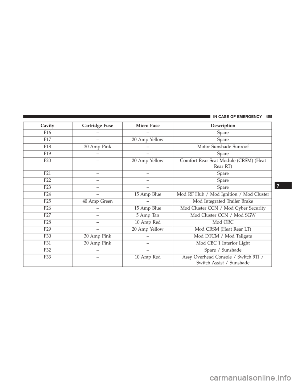
F25 40 Amp Green –Mod Integrated Trailer Brake
F26 –15 Amp Blue Mod Cluster CCN / Mod Cyber Security
F27 –5 Amp Tan Mod Cluster CCN / Mod SGW
F28 –10 Amp Red Mod ORC
F29 –20 Amp Yellow Mod CRSM (Heat Rear LT)
F30 30 Amp Pink –Mod DTCM / Mod Tailgate
F31 30 Amp Pink –Mod CBC 1 Interior Light
F32 –– Spare / Sunshade
F33 –10 Amp Red Assy Overhead Console / Switch 911 /
Switch Assist / Sunshade
7
IN CASE OF EMERGENCY 455