2019 Peugeot Expert connect
[x] Cancel search: connectPage 205 of 324
203
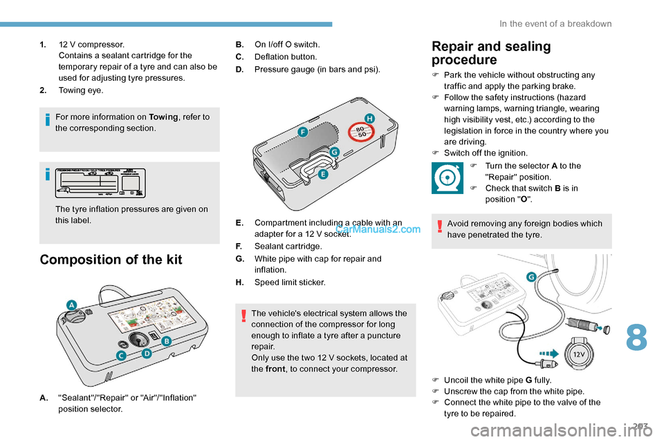
1.12 V compressor.
Contains a sealant cartridge for the
temporary repair of a tyre and can also be
used for adjusting tyre pressures.
2. Towing eye.
For more information on To w i n g , refer to
the corresponding section.
Composition of the kit
The tyre inflation pressures are given on
this label. B.
On I/off O switch.
C. Deflation button.
D. Pressure gauge (in bars and psi).
E. Compartment including a cable with an
adapter for a 12 V socket.
F. Sealant cartridge.
G. White pipe with cap for repair and
inflation.
H. Speed limit sticker.
The vehicle's electrical system allows the
connection of the compressor for long
enough to inflate a tyre after a puncture
repair.
Only use the two 12 V sockets, located at
the front , to connect your compressor.
Repair and sealing
procedure
F Park the vehicle without obstructing any
traffic and apply the parking brake.
F
F
ollow the safety instructions (hazard
warning lamps, warning triangle, wearing
high visibility vest, etc.) according to the
legislation in force in the country where you
are driving.
F
S
witch off the ignition.
A. "Sealant"/"Repair" or "Air"/"Inflation"
position selector. F
T
urn the selector A to the
"Repair" position.
F
C
heck that switch B is in
position " O".
Avoid removing any foreign bodies which
have penetrated the tyre.
F
U
ncoil the white pipe G fully.
F
U
nscrew the cap from the white pipe.
F
C
onnect the white pipe to the valve of the
tyre to be repaired.
8
In the event of a breakdown
Page 206 of 324
204
F Connect the compressor's electrical plug to the vehicle's 12 V socket.
F
A
ffix the speed limit sticker.
The speed limit sticker must be secured
to the interior of the vehicle in the driver's
field of vision, to remind you that a wheel
is in temporary use.
F
S
tart the vehicle and leave the engine
running.
Do not start the compressor before
connecting the white pipe to the tyre valve:
the sealant product would be expelled
through the pipe.
F
S
witch on the compressor by moving
switch B to position I until the tyre pressure
reaches 2.0 bars. The sealant product is
injected under pressure into the tyre; do not
disconnect the pipe from the valve during
this operation (risk of blowback). If after approximately seven minutes this
pressure is not reached, this indicates
that the tyre is not repairable; contact a
PEUGEOT dealer or a qualified workshop
for assistance.
F
R
emove the kit and screw the cap back
on the white pipe. Take care to avoid
contaminating the vehicle with traces of
fluid. Keep the kit to hand.
Take care, the sealant product is harmful
if swallowed and causes irritation to the
eyes.
Keep this product out of the reach of
children.
The use-by date of the fluid is marked on
the bottle.
After use, do not discard the bottle in
standard waste, take it to a PEUGEOT
dealer or an authorised waste disposal
site.
Do not forget to obtain a new bottle of
sealant, available from a PEUGEOT
dealer or a qualified workshop.
Inflation, occasional
inflation and checking
pressure
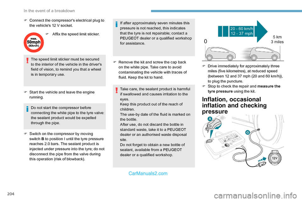
F Drive immediately for approximately three miles (five kilometres), at reduced speed
(between 12 and 37
mph (20 and 60 km/h)),
to plug the puncture.
F
S
top to check the repair and measure the
tyre pressure using the kit.
In the event of a breakdown
Page 207 of 324

205
F Turn selector A to the "Inflation" position.
F
U
ncoil the white pipe G fully.
F
C
onnect the white pipe to the
valve of the repaired wheel.
F
C
onnect the compressor's electrical plug to
the vehicle's 12 V socket again.
F
S
tart the vehicle and leave the engine
running.
As soon as possible, go to a PEUGEOT
dealer or a qualified workshop.
You must inform the technician that this kit
was used. After inspection, the technician
will tell you whether the tyre can be
repaired or if it must be replaced.
F
A
djust the pressure using the compressor
(to inflate: switch B in position " I"; to deflate:
switch B
in position " O" and press button
C),
in accordance with the vehicle's tyre
pressure label, located on the driver’s door
aperture.
A significant loss of pressure indicates that
the puncture has not been fully plugged;
contact a PEUGEOT dealer or a qualified
workshop for assistance.
F
R
emove the kit and stow it. F
D rive at reduced speed (50 mph
(80
km/h) max.) limiting the distance
travelled to approximately 125
miles
(2 0 0
k m).
It is also possible to use the compressor,
without injecting sealant, to check and, if
necessary, adjust the tyre pressures.
If after 7
minutes this pressure is not
reached, this indicates that the tyre is not
repairable; contact a PEUGEOT dealer or
a qualified workshop for assistance.
Do not drive more than 125 miles (200 km)
with a repaired tyre; contact a PEUGEOT
dealer or a qualified workshop to change
the tyre.
Should the pressure of one or more tyres
be adjusted, it is necessary to reinitialise
the under-inflation detection system.
For more information on Tyre under-
inflation detection , refer to the
corresponding section.Removing the pipe and
cartridge
F Turn the pipe assembly 2 to the left until it comes into contact with the unit.
F
D
isconnect the connector 1 from the
cartridge by turning it a quarter turn anti-
clockwise.
F
P
ull the pipe assembly 2 out slightly, then
disconnect the connector 3 from the air
intake pipe by turning it a quarter turn anti-
clockwise.
8
In the event of a breakdown
Page 214 of 324
212
Access to bulbs
Dipped beam headlamps
When refitting the connector and bulb
in the lamp, correctly reposition the
assembly in its housing until it clicks into
place.
Daytime running lamps
SidelampsMain beam headlamps
Direction indicators
Rapid flashing of a direction indicator
lamp (left or right) indicates that one of
the bulbs on the corresponding side has
failed.
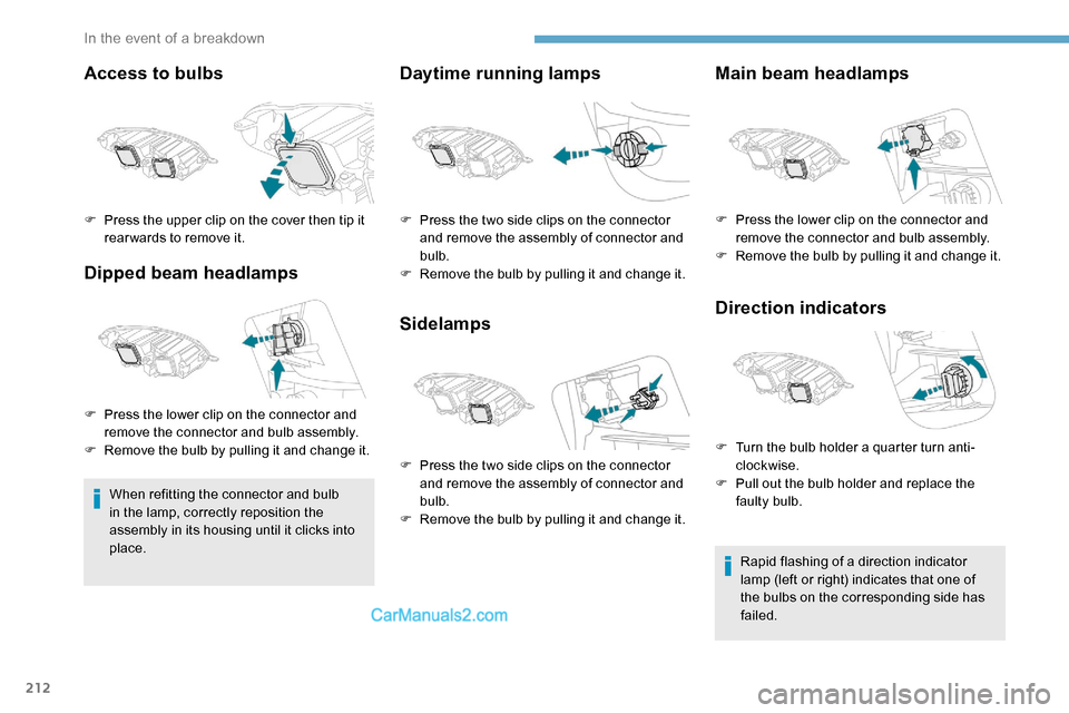
F
P
ress the upper clip on the cover then tip it
rear wards to remove it.
F
P
ress the lower clip on the connector and
remove the connector and bulb assembly.
F
R
emove the bulb by pulling it and change it. F
P
ress the two side clips on the connector
and remove the assembly of connector and
bulb.
F
R
emove the bulb by pulling it and change it.
F
P
ress the two side clips on the connector
and remove the assembly of connector and
bulb.
F
R
emove the bulb by pulling it and change it. F
P
ress the lower clip on the connector and
remove the connector and bulb assembly.
F
R
emove the bulb by pulling it and change it.
F
T
urn the bulb holder a quarter turn anti-
clockwise.
F
P
ull out the bulb holder and replace the
faulty bulb.
In the event of a breakdown
Page 215 of 324
213
Headlamps (xenon)
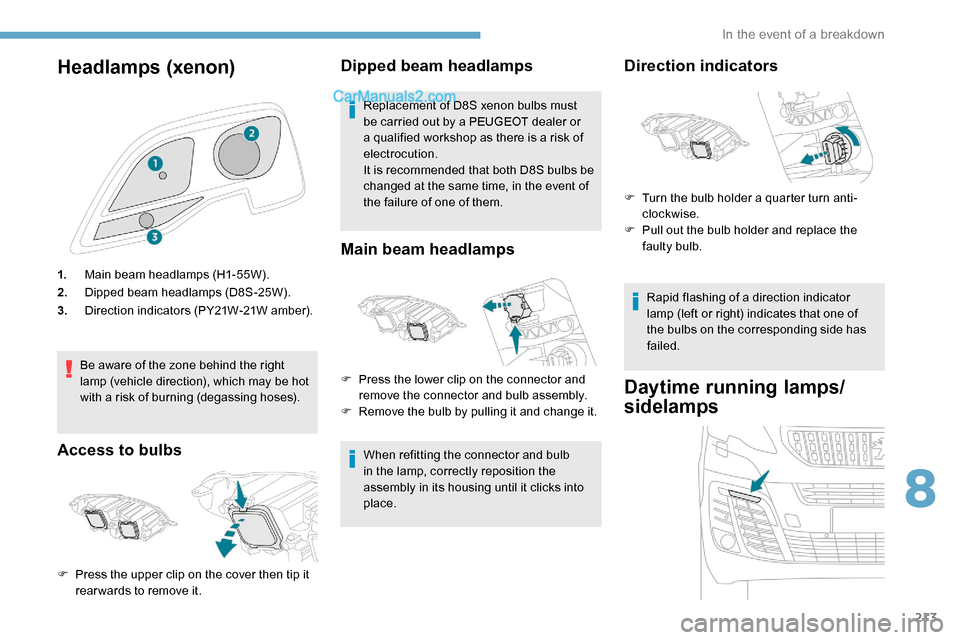
1.Main beam headlamps (H1-55W).
2. Dipped beam headlamps (D8S-25W).
3. Direction indicators (PY21W-21W amber).
Be aware of the zone behind the right
lamp (vehicle direction), which may be hot
with a risk of burning (degassing hoses).
Access to bulbs Dipped beam headlamps
Replacement of D8S xenon bulbs must
be carried out by a PEUGEOT dealer or
a qualified workshop as there is a risk of
electrocution.
It is recommended that both D8S bulbs be
changed at the same time, in the event of
the failure of one of them.
Main beam headlamps
When refitting the connector and bulb
in the lamp, correctly reposition the
assembly in its housing until it clicks into
place.
F
P
ress the upper clip on the cover then tip it
rear wards to remove it. F
P
ress the lower clip on the connector and
remove the connector and bulb assembly.
F
R
emove the bulb by pulling it and change it.
Direction indicators
Rapid flashing of a direction indicator
lamp (left or right) indicates that one of
the bulbs on the corresponding side has
failed.
Daytime running lamps/
sidelamps
F Turn the bulb holder a quarter turn anti-
clockwise.
F
P
ull out the bulb holder and replace the
faulty bulb.
8
In the event of a breakdown
Page 216 of 324
214
For the replacement of these bulbs, contact a
PEUGEOT dealer or a qualified workshop.
A replacement kit for the LEDs is available from
PEUGEOT dealers.
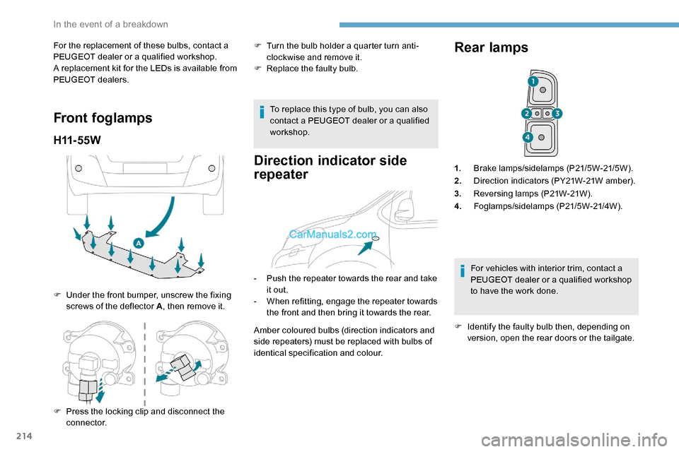
Front foglamps
H11- 5 5 W
F Under the front bumper, unscrew the fixing screws of the deflector A , then remove it.F
T
urn the bulb holder a quarter turn anti-
clockwise and remove it.
F
R
eplace the faulty bulb.
To replace this type of bulb, you can also
contact a PEUGEOT dealer or a qualified
workshop.
Direction indicator side
repeater
- Push the repeater towards the rear and take it out.
-
W
hen refitting, engage the repeater towards
the front and then bring it towards the rear.
Amber coloured bulbs (direction indicators and
side repeaters) must be replaced with bulbs of
identical specification and colour.
Rear lamps
1. Brake lamps/sidelamps (P21/5W-21/5W).
2. Direction indicators (PY21W-21W amber).
3. Reversing lamps (P21W-21W).
4. Foglamps/sidelamps (P21/5W-21/4W).
For vehicles with interior trim, contact a
PEUGEOT dealer or a qualified workshop
to have the work done.
F
I
dentify the faulty bulb then, depending on
version, open the rear doors or the tailgate.
F
P
ress the locking clip and disconnect the
connector.
In the event of a breakdown
Page 217 of 324
215
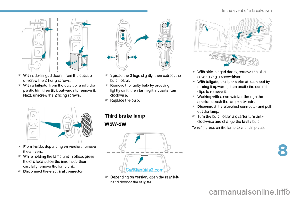
F With side-hinged doors, from the outside, unscrew the 2 fixing screws.
F
W
ith a tailgate, from the outside, unclip the
plastic trim then tilt it outwards to remove it.
Next, unscrew the 2 fixing screws.
F
F
rom inside, depending on version, remove
the air vent.
F
W
hile holding the lamp unit in place, press
the clip located on the inner side then
carefully remove the lamp unit.
F
D
isconnect the electrical connector. F
S pread the 3 lugs slightly, then extract the
bulb holder.
F
R
emove the faulty bulb by pressing
lightly on it, then turning it a quarter turn
clockwise.
F
R
eplace the bulb.
Third brake lampW5W-5W
F Depending on version, open the rear left- hand door or the tailgate. F
W
ith side-hinged doors, remove the plastic
cover using a screwdriver.
F
W
ith tailgate, unclip the trim at each end by
turning it upwards, then unclip the central
clips to remove it.
F
W
orking with a screwdriver through the
aperture, push the lamp outwards.
F
D
isconnect the electrical connector and pull
out the lamp.
F
T
urn the bulb holder a quarter turn anti-
clockwise and change the faulty bulb.
To refit, press on the lamp to clip it in place.
8
In the event of a breakdown
Page 220 of 324

218
PEUGEOT accepts no responsibility for
the cost incurred in repairing your vehicle
or for rectifying malfunctions resulting
from the installation of accessories
not supplied and not recommended by
PEUGEOT and not installed in accordance
with specifications, in particular when the
combined power consumption of all of the
additional equipment connected exceeds
10 milliamperes.
For more information on installing a
towbar or equipment of the TA XI type,
contact a PEUGEOT dealer.
Version 1 (Eco)
The fuses described below vary according to
the equipment in the vehicle.Fuse
No. Rating
(A) Functions
F4 15Horn.
F5 20Front/rear screenwash
pump.
F6 20Front/rear screenwash
pump.
F7 10Rear 12 V accessory
socket.
F8 20Single or double rear
wipers.
F10/F11 30Internal/external locks,
front and rear.
F14 5Alarm, emergency and
assistance calls
F24 5Touch screen,
reversing camera and
parking sensors.
F29 20Audio system, touch
screen, CD player,
navigation.
F32 15Front 12 V accessory
socket
Version 2 (Full)
The fuses described below vary according to
the equipment in the vehicle.
FuseNo. Rating
(A) Functions
F5 5Touch screen, reversing
camera and parking
sensors.
F8 20Single or double rear
wipers.
F10/F11 30Internal/external locks,
front and rear.
F12 3Alarm.
F17 10Rear 12 V accessory
socket.
F33 15Front 12 V accessory
socket
F36 20Audio system, touch
screen, CD player,
navigation.
In the event of a breakdown