2019 MERCEDES-BENZ SPRINTER ECU
[x] Cancel search: ECUPage 185 of 354

R
Ifth e trailer has electronically cont rolled
brakes, pull away carefully wi th theve hicle/
trailer combination. Brake manually using the
brake controller and check whe ther the
brakes are functioning cor rectly.
R Secu rethe load on the trailer in line with the
re qu irements and rules for load-securing
me thods.
R When driving with a trailer, check at regular
inter vals that the load is secure and that the
lights and brakes are functioning cor rectl y.
R Bear in mind that the handling characteristics
are more uns table when towing a trailer than
when driving without a trailer. Avoid sudden
st eering mo vements.
R The vehicle/trailer combination is heavier,
accelerates more slowl y,has a reduced
climbing ability and an increased braking dis‐
ta nce. It is more susceptible toside winds
and requ ires careful steering.
R If possible, do not brake suddenl y,but rath er
moderately at firs t so that the trailer can acti‐
va te its brakes. Then inc rease the pressure on
th e brake pedal.
R Ifth e automatic transmission shifts between
ge ars on uphill or downhill gradients, restrict
th e shift range. Select shi ftrange 4, 3, 2 or 1.
A lo werge ar and reduced speed decrease the
ri sk of engine damage.
R When driving on a downhill gradient, shift to a
lo we rge ar to use the engine's braking ef fect.
Av oid cons tant braking, as this could cause
th eve hicle brakes and possibly also the
trailer brakes toove rheat.
R Ifth e coolant temp erature increases signifi‐
cantly when the air-conditioning sy stem is
switched on, switch the air-conditioning sys‐
te m off.
Coolant heat can also be dissipated by
switching the air flow and thete mp erature of
th e heater or air conditioning tothe maximum
le ve l. Open the windo wsif necessar y.
R When overtaking, pay particular attention to
th e increased overtaking di stance of your
ve hicle/trailer combination.
Due tothe length of your vehicle/trailer com‐
bination you will requ ire a longer stre tch of
ro ad before swit ching back tothe original
lane. Pe
rm issible trailer loads and trailer dr awbar
nose weights We
ight information &
WARNING Risk of accident due to
unbraked trailer with excessively high
gross weight
If yo uto w a trailer without a separate func‐
tional braking sy stem and a gross trailer
we ight (G TW) of more than 1635 lbs (750 kg),
th en theve hicle brake sy stem may overheat.
This increases the braking dis tance and the
brake sy stem may evenfa il. #
Always use a trailer with a separate
functional braking sy stem when towing
a trailer with a gross trailerweight
(G TW ) of more than 1635 lbs (750 kg). *
NO
TEDama getothe drive train, trans‐
mission or trailer tow hit chdue toexc ess
gross combination weight The permissible
gross combinationweight is
exc eeded.
The drive train, the transmission or the trailer
to w hit chmay be dama ged. #
Comply with the permissible gross com‐
bination weight. Fo
rve hicles with a permissible gross vehicle
we ight of 11030 lbs (5003 kg),th e permissible
gross combination weight is less than the sum of
th e permissible gross vehicle weight plus the per‐
missible trailer load. If either theve hicle or the
trailer is fully laden, the permitted gross vehicle
we ight or the permitted trailer load values are
re duced accordingly. In this case, you may on ly
partially load the trailer or theve hicle.
The gross trailer weight (G TW) is calculated by
adding thewe ight of the trailer tothewe ight of
th e load and equipment. If the trailer is equipped
with a separate braking sy stem, then the maxi‐
mum gross trailer weight is 5000 lbs (2268 kg) or
75 00 lbs (3402 kg).
The maximum permissible trailer dr awbar nose‐
we ight on the ball head is 500 lbs (227 kg) or
75 0 lbs (340 kg). Ho wever,th e actual trailer
dr aw bar nose weight must not exceed theva lue
given on the trailer tow hit chor trailer identifica‐
tion plates. Where theva lues dif fer, th e lo west
va lue alw ays applies. Driving and parking
161
Page 191 of 354

Instrument Display with color display
The
following status displa ysare available on the
assis tant displ ay:
R 00D7 :AT TENTION ASSIST switched off
R Displa ysoftheAc tive Dis tance Assi st
DISTRONIC (/ page 143) In
stru ment Display with black and white display
The following status displa ysare available on the
assis tant displ ay:
R Lane markings dotted: Lane Keeping Assist
switched off
R Lane markings solid and thin: Lane Keeping
Assist switched on, not ready toissue warn‐
ings
R Lane markings solid and thick: Lane Keeping
Assist ready toissue warnings Calling up displa
yson the trip menu On-board computer:
4 Trip #
Select the desired display and confirm.
The following displa ysare available on the trip
menu:
R Standard display R
Range and cur rent fuel consu mption
Wi th cer tain engines a recuperation display is
also shown. If only a small amount of fuel is
left in the fuel tank, a vehicle being refueled
appears ins tead of the appr oximate range.
R ECO displ ay (/page 113)
R Trip computer:
- From Start
- From Reset
R Digital speedom eter Instrument Display with color display
Standard display (e xamp le)
1 Trip dis tance
2 Total dis tance Instrument Display wi
thblack and white display
St andard display (e xamp le)
1 Trip dis tance
2 Total dis tance Instrument Display and on-board compu
ter167
Page 207 of 354

Multimedia sy
stem:
4 © 5
Phone 5
00A5
Sear ching for a mobile phone #
Select Connect New Device.
Connecting a mobile phone (authorization
using Secure Si mplePa iring) #
Select a mobile phone. #
A code is displa yed in the multimedia sy stem
and on the mobile phone. #
Ifth e codes match: confirm the code on the
mobile phone.
% Fo
r older mobile phone models, enter a one
to sixteen-digit number code on the mobile
phone and on the multimedia sy stem for
authorization.
% Up
to15 mobile phones can be authorized on
th e multimedia sy stem.
Auth orized mobile phones are reconnected
au tomatical ly.
% The connected mobile phone can also be
used as Blue tooth®
audio equipment
(/ page 190).
Re placing a mobile phone
Multimedia sy stem:
4 Phone 5
00A5 #
Noauthorized mobile phone available:
select Connect New Device .#
Select a mobile phone. #
Newly authorized mobile phone: confirm
th e number code on the mobile phone.
Switching mobile phones #
Select an authorized mobile phone.
The selected mobile phone is connected to
th e multimedia sy stem.
% For iPhone ®
:yo u can swit chbetween the
Apple CarPl ay™ and Blu etoo th®
equipment
connection variants.
De-authorizing a mobile phone
Multimedia sy stem:
4 © 5
Phone 5
00A5 #
Select 0062inthe line of the mobile phone. #
Select Deauthorize . Information on
NearField Communication
(NFC)
NFC enables short- range wi reless data transfer
or (re)connection of a mobile phone with the mul‐
timedia sy stem.
Fu rther information can be obtained at: http://
www.mercedes-benz.com/connect
Using the mobile phone with NearField Com‐
munication (NFC)
Re quirements:
R NFC is activated on the mobile phone (see
th e manufacturer's operating instructions)
R The mobile phone's screen is switched on
and unloc ked (see the manufacturer's operat‐
ing instructions) #
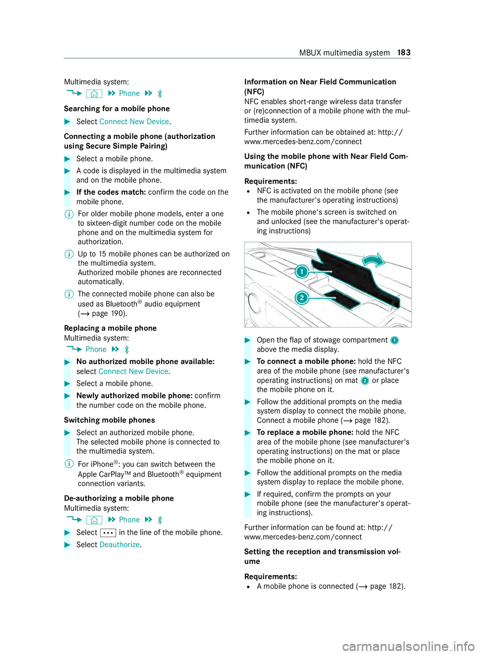
Open theflap of stowage compartment 1
abo vethe media displa y. #
Toconnect a mobile phone: holdthe NFC
area of the mobile phone (see manufacturer's
operating instructions) on mat 2or place
th e mobile phone on it. #
Follow the additional prom pts on the media
sy stem display toconnect the mobile phone.
Connect a mobile phone (/ page182). #
Toreplace a mobile phone: holdthe NFC
area of the mobile phone (see manufacturer's
operating instructions) on the mat or place
th e mobile phone on it. #
Follow the additional prom pts on the media
sy stem display toreplace the mobile phone. #
Ifre qu ired, con firm the prom pts on your
mobile phone (see the manufacturer's operat‐
ing instructions).
Fu rther information can be found at: http://
www.mercedes-benz.com/connect
Setting there ception and transmission vol‐
ume
Re quirements:
R A mobile phone is connec ted (/ page182). MBUX multimedia sy
stem 18 3
Page 219 of 354

Note
s on loading guidelines &
DANG ER Risk of poisoning from exhaust
ga ses
Combustion engines emit poisonous exhaust
ga ses, such as carbon monoxide. Exhaust
ga ses can enter theve hicle interior if the
re ar-end door is open when the engine is run‐
ning, especially if theve hicle is in motion. #
Always switch off the engine before
opening there ar-end door. #
Never drive with there ar-end door
open. &
WARNING Risk of inju ryfrom unsecu red
objects in theve hicle
When objects are unsecured or inadequately
secured, they can slip, tip over or be thro wn
about, striking vehicle occupants.
This also applies to:
R Luggage or loads
R Seats which ha vebeen remo ved and are
being transpor ted in theve hicle in an
ex ceptional case
The reis a risk of injur y,particular lyin the
eve nt of braking maneuvers or ab rupt
ch anges in direction. #
Alwaysstow objects in such a wayth at
th ey cannot be tossed about. #
Before tr aveling, secure objects, lug‐
ga ge or load topreve ntthem slipping or
tipping over. #
When a seat is remo ved, keep it prefera‐
bly outside theve hicle. &
WARNING Risk of inju rydue toobjects
being stowed incor rectly
If yo u do not adequately stowobjects in the
ve hicle interior, they could slip or be tossed
around and thereby strike vehicle occupants.
In addition, cup holders, open stowage
spaces and mobile phone brac kets cannot
al wa ys restra in the objects they contain in the
eve nt of an accident.
The reis a risk of injur y,particular lyin the
eve nt of sudden braking or a sudden change
in direction. #
Alwaysstow objects in such a wayth at
th ey cannot be tossed about in these or
similar situations. #
Always make sure that objects do not
project from stowage spaces, parcel
nets or stowage nets. #
Close the loc kable stow age spaces
before starting a journe y. #
Stow and secure objects that are heavy,
hard, poin ted, sharp-edged, fragile or
to o lar geinthe cargo compartment. &
WARNING Risk of bu rning from theta il‐
pipe or tailpipe trim
The tailpipe and tailpipe trim can become
ve ry hot. If you come into con tact wi th these
car parts, you could burn yourself. #
Always be particularly careful when in
th e vicinity of theta ilpipe and tailpipe
trims and supervise children very
closely when in this area. #
Before any con tact, allow the car parts
to cool down. If
yo u are using a roof rack , please no tethe maxi‐
mum roof load and the maximum load capacity of
th ero of rack.
Yo u will find information about the maximum roof
load in the "Technical data" chap ter and informa‐
tion about roof rack s in the "Car rier sy stems"
section .
Camera-based driving sy stems and the sensor
functions of the inside rearview mir ror may be
impaire d ifyou are transpo rting a load on the
ro of and it pr otru des more than 16 in (40 cm)
ove rth e edge of thero of. Therefore, make sure
th at the load does not overhang bymore than
16 in (40 cm).
The handling characteristics of your vehicle are
dependent on the load distribution. Therefore,
please obser vethefo llowing no tes when loading:
R when transporting a load, ne verex ceed the
permissible gross mass or the gross axle
we ight rating forth eve hicle (including occu‐
pants). The values are specified on theve hi‐
cle identification plate on the B-pillar.
R the load must not pr otru de abo vethe upper
edge of the seat backrests.
R if possible, alw ays transport the load in the
cargo compa rtment. Tr
ansporting 19 5
Page 220 of 354

R
fastenthe load tothe tie-down eyes and
spread the load as evenly as possible.
R use tie-down eyes and fastening components
which are suitable forth ewe ight and size of
th e load. Load distribution
* NO
TERisk of damage tothefloor co ver‐
ing Excessive point loading on
the cargo com‐
partment floor or on the load area can nega‐
tively af fect the driving characteristics and
could damage thefloor co vering. #
Vehicles with rear-wheel drive: dis‐
tribu tethe load uniformly. When doing
so, ensure that theove rall cen ter of
gr av ity of the load is alw ays as low and
close tothe center as possible and
between the axles near there ar axle. #
Vehicles with all-wheel drive: distrib‐
ute the load uniforml y.When doing so,
ensure that theove rall cen ter of gr avity
of the load is alw ays as low and close to
th e center as possible and between the
axles. Excessive point loading on
the cargo compart‐
ment floor or on the load area can negatively
af fect the driving characteristics and could dam‐
age thefloor co vering.
On Cargo Van and Passenger Van:
R alwa ys transpo rtthe load in the cargo com‐
partment.
R alwaysfast enthe load tothere ar ben chseat
backrests.
R movelarge and heavy loads as farto wa rds
th e front of theve hicle as possible against
th ere ar ben chseat. Stow loads flush with the
re ar ben chseat.
R always additionally secure the load with suita‐
ble load securing aids or tie downs.
R the load must not pr otru de abo vethe upper
edge of the seat backrests.
R transport loads behind seats that are not
occupied.
R ifth ere ar ben chseat is not occupied, insert
th e seat belts crosswise into the buckle of the
opposite seat belt. Securing loads
Note
s on load securing &
WARNING Risk of accident and injury
due toincor rect use of the lashing stra ps
If yo u attach the lashing stra p incor rectly
when secu ring loads, thefo llowing may occur
in theev ent of abrupt changes in direction,
braking maneuver or an acciden t:
R The tie-down eyes may become de tach ed
or the lashing stra p may tear if the per‐
missible load is exceeded.
R The load cann otbe restra ined.
This may cause the load toslip, tip over or be
fl ung about, striking vehicle occupants. #
Alwayste nsion the lashing stra ps in the
proper manner and only between the
described tie-down eyes. #
Always use lashing stra ps designed spe‐
cifically forth e loads. %
Obser
vethe information relating tothe maxi‐
mum loading capacity of the individual cargo
tie-down point. If you combine various cargo
tie-down points tosecure a load, alw aysta ke
th e maximum loading capacity of thewe ak‐
est cargo tie-down point into account. During
maximum full- stop braking, forc es may act
which can multiply thewe ight of the load.
Alw ays use se veral cargo tie-down points to
distribute and spread the load. Spread the
load evenly between the cargo tie-down
points or tie-down eyes.
Alw ays obser vethe operating instructions or the
lashing stra p manufacturer's instructions forthe
operation of the lashing stra p.
Obser vethe information relating tothe maximum
loading capacity of the cargo tie-down points
(/ page 275).
As the driver, you are responsible for ensuring the
fo llowing:
R The load is secured against slipping, tipping,
rolling or falling off.
Ta ke usual traf fic conditions as well as swerv‐
ing or full brake application and bad roads
into account.
R The applicable requ irements and guidelines
re lating toload-securing practices are met.
If th is is not the case, this may con stitute a
punishable of fense, depending on local legis‐ 19 6
Transporting
Page 221 of 354

lation and any ensuing consequences.
Obser
vecountr y-specific la ws.
Make sure that the load is secure before every
jou rney and at regular inter vals during a long
journe y.Ad just the load securing as necessar y.
Information on how tosecure loads cor rectly can
be obtained from the manufacturers of load
securing aids or tie downs for load-securing, for
ex ample.
When securing loads, obse rveth efo llowing:
R Fill spaces between the load and the cargo
compartment walls or wheel wells. Forth is
purpose, use rigid load securing aids, such as
we dges, wooden fixings or padding.
R Attach secured and stabilized loads in all
directions.
Use the cargo tie-down points or tie-down
ey es and the loading rails in the cargo com‐
partment or on the load sur face.
Only use tie downs, such as lashing rods, lock
ro ds or lashing nets and lashing stra ps, which
has been tested in accordance with cur rent
st andards (e.g. DIN EN). Alw ays use the cargo
tie-down point closest tothe load; pad sharp
edges.
Loads, and heavy loads in particular, should
preferably be secured using the tie-down
ey es.
% Yo
u will obtain tie downs tested in accord‐
ance with cur rent standards (e.g. DIN EN)
from any specialist company or from a quali‐
fi ed specialist workshop.
Note s onthe pa rtition
Wi thout a partition, vehicles that are appr oved as
commercial vehicles (N1, N2) do not fulfill ISO
27 956, whi chdescribes the equipment for prop‐
erly securing a load in deli very vehicles. If the
ve hicle is used totranspo rtgoods, retrofitting the
partition is stro ng lyrecommended, as prope rly
securing the load in vehicles without a partition
will alw ays be a complex operation. Overview of cargo tie-down point
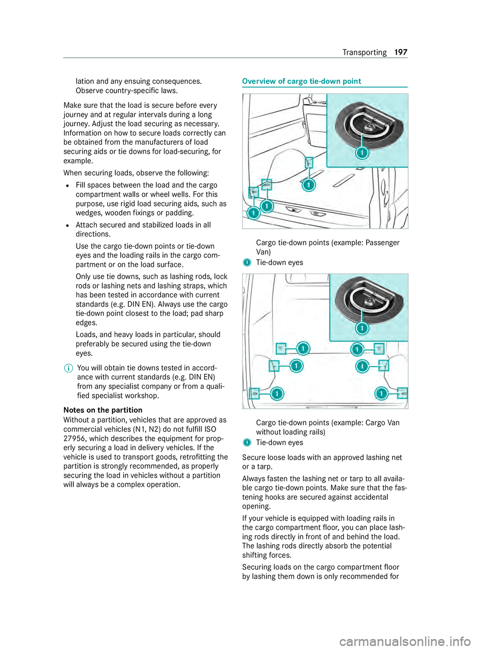
Cargo tie-down points (e
xample:Passenger
Va n)
1 Tie-down eyes Cargo tie-down points (e
xample: Cargo Van
without loading rails)
1 Tie-down eyes
Secure loose loads with an appr oved lashing net
or a tarp.
Alw aysfast enthe lashing net or tarp toall availa‐
ble cargo tie-down points. Make sure that thefa s‐
te ning hoo ksare secured against acciden tal
opening.
If yo ur vehicle is equipped with loading rails in
th e cargo compartment floor, you can place lash‐
ing rods directly in front of and behind the load.
The lashing rods directly absorb the po tential
shi fting forc es.
Securing loads on the cargo compartment floor
by lashing them down is only recommended for Tr
ansporting 197
Page 222 of 354

light
weight loads. Lay anti-slip mats underneath
th e load tosecure the load additionally. Installing and
removing tie-down eyes #
Toinstall: slidethe tie-down eyeth ro ugh a
re cess in the loading rail close tothe load
until locking mechanism engages in the
re cess.
% When
you pull locking mechanism up and out
of there cess, the tie-down eye is able to
mo vewithin the loading rail. Make sure that
locking mechanism is alw ays engaged in a
re cess. #
Che ckthe tie-down eyefo rfirm seating. #
Toremo ve:pull lo cking mechanism up and
pull the tie-down eyeto wa rdsth e locking
mechanism and out of the loading rail
th ro ugh a recess. Car
rier sy stems Information about
thero of rack &
WARNING Risk of inju rydue tothe maxi‐
mum roof load being exceeded
When you place a load on thero of as well as
all outer and inner attachments, theve hicle's
center of gr avity will rise and thefa miliar driv‐
ing characteristics as well as thesteering and
braking characteristics will change. When
driving around bends, theve hicle will tilt
more heavily and may react more sluggishly
to steering mo vements.
If yo uexc eed the maximum roof load, the
driving characteristics, as well as thesteering
and braking, will be greatly impaired. #
Neverexc eed the maximum roof load
and adjust your driving style. 1
Mounting rails
Information about the maximum roof load can be
fo und in the "Technical data" section
(/ page 276).
Obse rveth efo llowing points for assembling roof
ra ck s:
R Tighten thero of rack 's scr ewsto ato rque of
6.0 lb -ft(8 Nm) – 7.4 lb-f t(10 Nm) in the des‐
ignated groo ved plates.
R The tightened scr ews should not touch the
ra ils.
R Ensure that the groo ved plates are not loca‐
te d in the areas around the plastic caps.
R The groo ved plates must ha vetheright cross-
section.
R The insides of the mounting rails must be free
of dirt.
R Re-tigh tenth e scr ews uniformly af ter around
300 miles (500 km).
Mercedes-Benz recommends that you use on ly
ro of rack sth at ha vebeen tested and appr oved
fo r Mercedes-Benz. These help topreve ntvehicle
damage.
If yo uwa nttoretrofit the mounting rails, ha ve
th em ins talled at a qualified specialist workshop.
Otherwise, you could damage theve hicle.
If yo ur vehicle is ins talled with mounting rails on
th ero of, you can install a roof rack on thero of.
Special fasteners (sliding bloc ks) are available as
accesso ries forth is purpose.
These fasteners are available from any authorized
Mercedes-Benz Center. 19 8
Transporting
Page 223 of 354

Using the interior
roof car rier sy stem &
WARNING Risk of inju rydue tounse‐
cured loads
When you secure or loosen a load, the load
may fall down and injure vehicle occupants. #
When securing or loosening a load, do
not stand under the load. *
NO
TERisk of damage tothe belt stra ps
and slider Excessive point loading on
the belt stra ps and
sliders may cause the belt stra ps totear or cause
the sliders tobreak off from thera ck
ra il. #
Distribute the load evenly. When doing
so, ensure that theove rall cen ter of
gr av ity of the load is alw ays as close to
th e center as possible and between the
ro of rails and between thera ck rails. Yo
u can use the interior roof rack system to
secure loads. It is also suitable for securing long
loads.
% The interior
roof rack system may be subjec‐
te dto a maximum load of 110 lbs (50 kg).
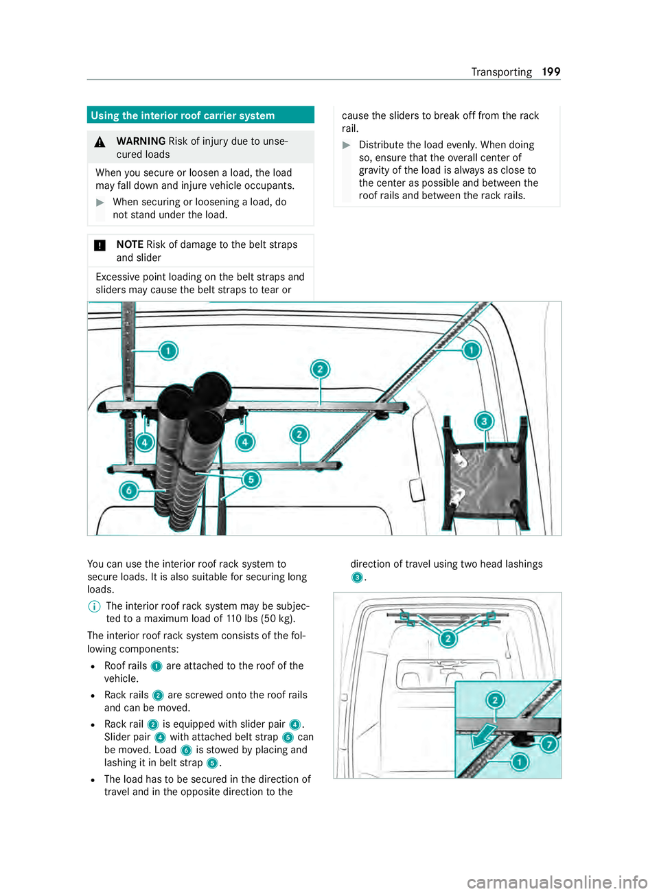
The interior roof rack system consists of thefo l‐
lowing components:
R Roofrails 1 are attached tothero of of the
ve hicle.
R Rack rails 2 are scr ewed onto thero of rails
and can be mo ved.
R Rack rail2 is equipped with slider pair 4.
Slider pair 4with attached belt stra p5 can
be mo ved. Load 6isstowe dby placing and
lashing it in belt stra p5.
R The load has tobe secured in the direction of
tra vel and in the opposite direction tothe direction of tra
vel using two head lashings
3. Tr
ansporting 19 9