2019 MERCEDES-BENZ GLE COUPE flat tire
[x] Cancel search: flat tirePage 335 of 370
Avoid tire pressures that are too low in all the
tires, including the spare wheel.
Underinflated tires may:
R overheat, leading to tire defects
R adversely affect handling
R wear excessively and/or unevenly
R have an adverse effect on fuel consumption
Overinflated tires G
WARNING
Tires with excessively high pressure can burst
because they are damaged more easily by
road debris, potholes etc. In addition, they
also suffer from irregular wear, which can
severely impair the braking properties and the driving characteristics. There is a risk of an
accident.
Avoid tire pressures that are too high in all the
tires, including the spare wheel.
Overinflated tires may: R increase the braking distance
R adversely affect handling
R wear excessively and/or unevenly
R have an adverse effect on ride comfort
R be more susceptible to damage
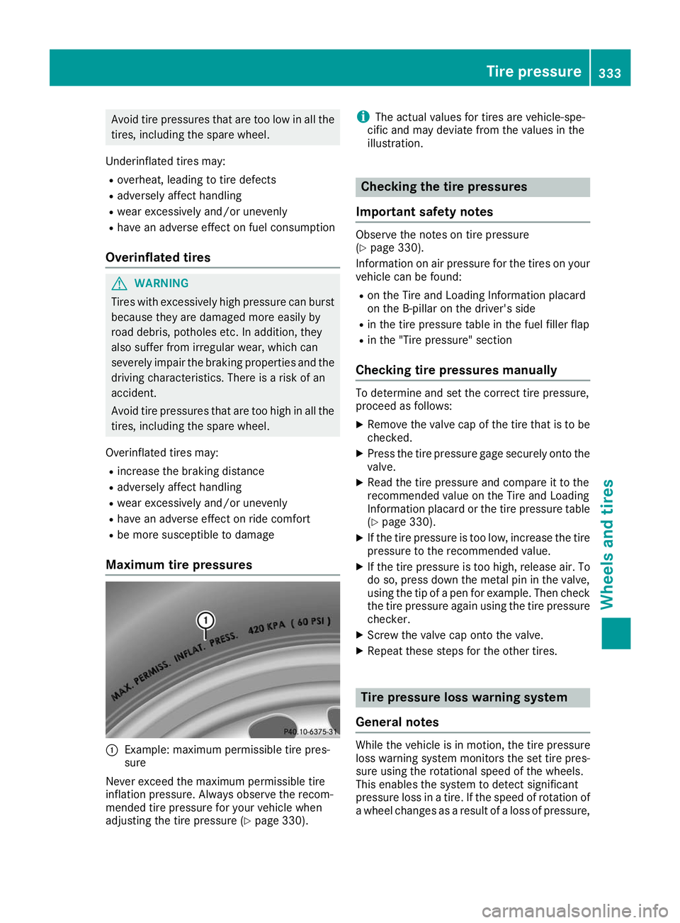
Maximum tire pressures 0043
Example: maximum permissible tire pres-
sure
Never exceed the maximum permissible tire
inflation pressure. Always observe the recom-
mended tire pressure for your vehicle when
adjusting the tire pressure (Y page 330).i
The actual values for tires are vehicle-spe-
cific and may deviate from the values in the
illustration. Checking the tire pressures
Important safety notes Observe the notes on tire pressure
(Y
page 330).
Information on air pressure for the tires on your vehicle can be found:
R on the Tire and Loading Information placard
on the B-pillar on the driver's side
R in the tire pressure table in the fuel filler flap
R in the "Tire pressure" section
Checking tire pressures manually To determine and set the correct tire pressure,
proceed as follows:
X Remove the valve cap of the tire that is to be
checked.
X Press the tire pressure gage securely onto the
valve.
X Read the tire pressure and compare it to the
recommended value on the Tire and Loading
Information placard or the tire pressure table
(Y page 330).
X If the tire pressure is too low, increase the tire
pressure to the recommended value.
X If the tire pressure is too high, release air. To
do so, press down the metal pin in the valve,
using the tip of a pen for example. Then check the tire pressure again using the tire pressure
checker.
X Screw the valve cap onto the valve.
X Repeat these steps for the other tires. Tire pressure loss warning system
General notes While the vehicle is in motion, the tire pressure
loss warning system monitors the set tire pres-
sure using the rotational speed of the wheels.
This enables the system to detect significant
pressure loss in a tire. If the speed of rotation of
a wheel changes as a result of a loss of pressure, Tire pressure
333Wheels and tires Z
Page 336 of 370
a corresponding warning message will appear in
the multifunction display.
You can recognize the tire pressure loss warning
by the Run Flat Indicator Active Press Run Flat Indicator Active Press
'OK' to Restart
'OK' to Restart message which appears in
the Service
Service menu of the multifunction display.
Information on the message display can be
found in the "Restarting the tire pressure loss
warning system" section (Y page 334).
Important safety notes The tire pressure warning system does not warn
you of an incorrectly set tire pressure. Observe
the notes on the recommended tire pressure
(Y page 330).
The tire pressure loss warning does not replace
the need to regularly check the tire pressure. An even loss of pressure on several tires at the
same time cannot be detected by the tire pres-
sure loss warning system.
The tire pressure monitor is not able to warn you of a sudden loss of pressure, e.g. if the tire is
penetrated by a foreign object. In the event of a
sudden loss of pressure, bring the vehicle to a
halt by braking carefully. Avoid abrupt steering
movements.
The function of the tire pressure loss warning
system is limited or delayed if:
R snow chains are mounted on your vehicle's
tires.
R road conditions are wintry.
R you are driving on sand or gravel.
R you adopt a very sporty driving style (corner-
ing at high speeds or driving with high rates of
acceleration).
R you are driving with a heavy load (in the vehi-
cle or on the roof).
Restarting the tire pressure loss warn-
ing system Restart the tire pressure loss warning system if
you have:
R changed the tire pressure
R changed the wheels or tires
R mounted new wheels or tires
X Before restarting, make sure that the tire
pressures are set properly on all four tires for
the respective operating conditions.
The recommended tire pressure can be found on the Tire and Loading Information placard on the B-pillar. Additionally, a tire pressure
table is attached to the fuel filler flap. The tire
pressure loss warning system can only give
reliable warnings if you have set the correct
tire pressure. If an incorrect tire pressure is
set, these incorrect values will be monitored.
X Also observe the notes in the section on tire
pressures (Y page 330).
X Make sure that the SmartKey is in position 0048
in the ignition lock (Y page 127).
X Press the 0059or0065 button on the steering
wheel to select the Service
Service menu.
X Press the 0063or0064 button to select
Tire Pressure Tire Pressure.
X Press the 0076button.
The Run Flat Indicator Active Press
Run Flat Indicator Active Press
'OK' to Restart
'OK' to Restart message appears in the
multifunction display.
If you wish to confirm the restart:
X Press the 0076button.
The Tire Pressure Now OK?
Tire Pressure Now OK? message
appears in the multifunction display.
X Press the 0063or0064 button to select Yes
Yes.
X Press the 0076button.
The Run Flat Indicator Restarted
Run Flat Indicator Restarted mes-
sage appears in the multifunction display.
After a teach-in period, the tire pressure loss
warning system will monitor the set tire pres-
sures of all four tires.
If you wish to cancel the restart: X Press the 0038button.
or
X When the Tire
TirePressure
Pressure Now
NowOK?
OK?message
appears, press the 0063or0064 button to
select Cancel
Cancel .
X Press the 0076button.
The tire pressure values stored at the last
restart will continue to be monitored. Tire pressure monitor
General notes If a tire pressure monitor is installed, the vehi-
cle's wheels have sensors that monitor the tire
pressures in all four tires. The tire pressure mon-
itor warns you if the pressure drops in one or
more of the tires. The tire pressure monitor only functions if the corresponding sensors are
installed in all wheels. 334
Tire pressureWheels and tires
Page 337 of 370
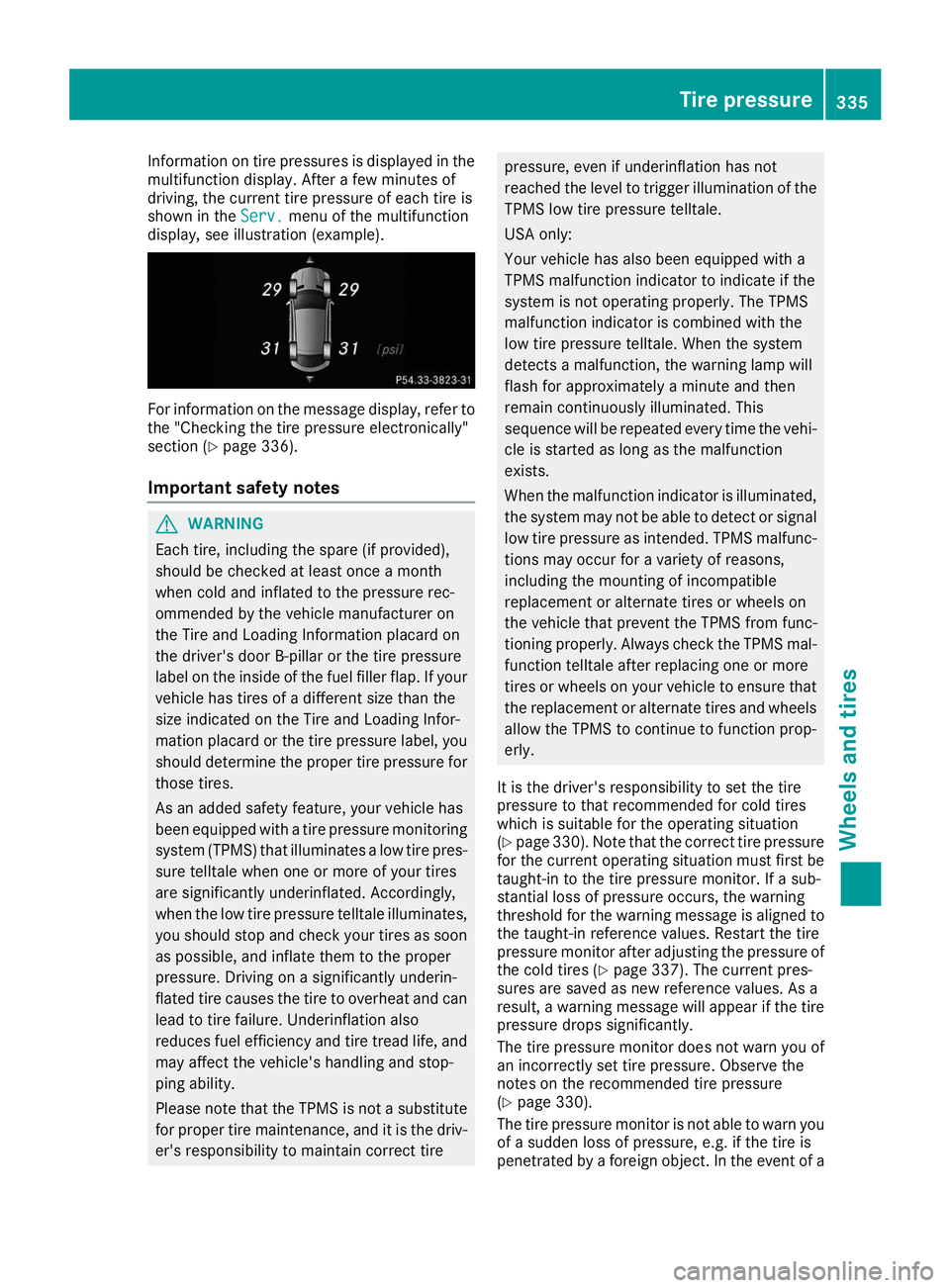
Information on tire pressures is displayed in the
multifunction display. After a few minutes of
driving, the current tire pressure of each tire is
shown in the Serv.
Serv. menu of the multifunction
display, see illustration (example). For information on the message display, refer to
the "Checking the tire pressure electronically"
section (Y page 336).
Important safety notes G
WARNING
Each tire, including the spare (if provided),
should be checked at least once a month
when cold and inflated to the pressure rec-
ommended by the vehicle manufacturer on
the Tire and Loading Information placard on
the driver's door B-pillar or the tire pressure
label on the inside of the fuel filler flap. If your vehicle has tires of a different size than the
size indicated on the Tire and Loading Infor-
mation placard or the tire pressure label, you should determine the proper tire pressure for
those tires.
As an added safety feature, your vehicle has
been equipped with a tire pressure monitoring system (TPMS) that illuminates a low tire pres-
sure telltale when one or more of your tires
are significantly underinflated. Accordingly,
when the low tire pressure telltale illuminates,
you should stop and check your tires as soon
as possible, and inflate them to the proper
pressure. Driving on a significantly underin-
flated tire causes the tire to overheat and can lead to tire failure. Underinflation also
reduces fuel efficiency and tire tread life, and may affect the vehicle's handling and stop-
ping ability.
Please note that the TPMS is not a substitute
for proper tire maintenance, and it is the driv-
er's responsibility to maintain correct tire pressure, even if underinflation has not
reached the level to trigger illumination of the
TPMS low tire pressure telltale.
USA only:
Your vehicle has also been equipped with a
TPMS malfunction indicator to indicate if the
system is not operating properly. The TPMS
malfunction indicator is combined with the
low tire pressure telltale. When the system
detects a malfunction, the warning lamp will
flash for approximately a minute and then
remain continuously illuminated. This
sequence will be repeated every time the vehi-
cle is started as long as the malfunction
exists.
When the malfunction indicator is illuminated,
the system may not be able to detect or signal low tire pressure as intended. TPMS malfunc-tions may occur for a variety of reasons,
including the mounting of incompatible
replacement or alternate tires or wheels on
the vehicle that prevent the TPMS from func-
tioning properly. Always check the TPMS mal-
function telltale after replacing one or more
tires or wheels on your vehicle to ensure that
the replacement or alternate tires and wheels
allow the TPMS to continue to function prop-
erly.
It is the driver's responsibility to set the tire
pressure to that recommended for cold tires
which is suitable for the operating situation
(Y page 330). Note that the correct tire pressure
for the current operating situation must first be
taught-in to the tire pressure monitor. If a sub-
stantial loss of pressure occurs, the warning
threshold for the warning message is aligned to the taught-in reference values. Restart the tire
pressure monitor after adjusting the pressure of
the cold tires (Y page 337). The current pres-
sures are saved as new reference values. As a
result, a warning message will appear if the tire
pressure drops significantly.
The tire pressure monitor does not warn you of
an incorrectly set tire pressure. Observe the
notes on the recommended tire pressure
(Y page 330).
The tire pressure monitor is not able to warn you of a sudden loss of pressure, e.g. if the tire is
penetrated by a foreign object. In the event of a Tire pressure
335Wheels and tires Z
Page 343 of 370
All about wheels and tires
Uniform Tire Quality Grading Stand-
ards
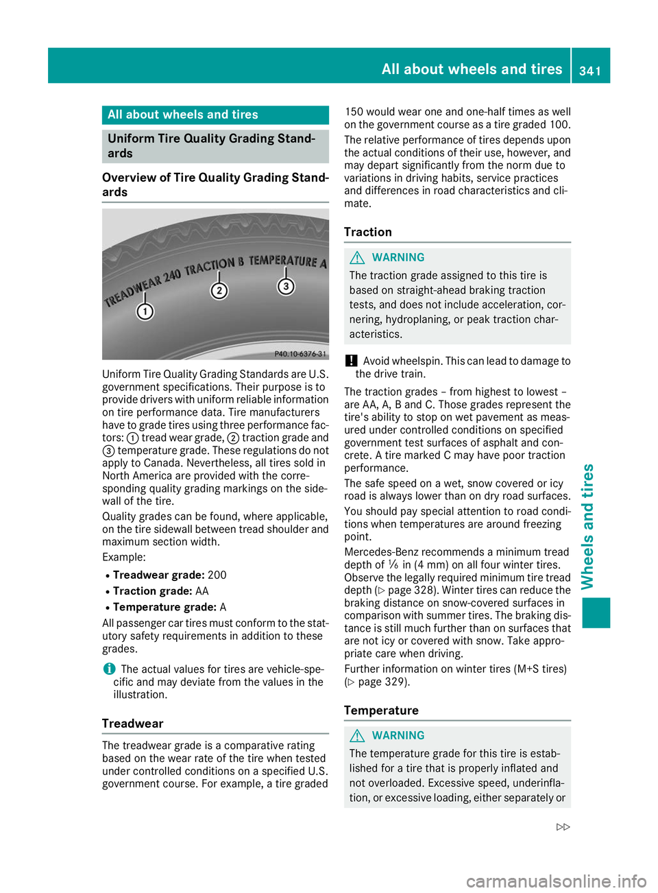
Overview of Tire Quality Grading Stand- ards Uniform Tire Quality Grading Standards are U.S.
government specifications. Their purpose is to
provide drivers with uniform reliable information on tire performance data. Tire manufacturers
have to grade tires using three performance fac-
tors: 0043tread wear grade, 0044traction grade and
0087 temperature grade. These regulations do not
apply to Canada. Nevertheless, all tires sold in
North America are provided with the corre-
sponding quality grading markings on the side-
wall of the tire.
Quality grades can be found, where applicable,
on the tire sidewall between tread shoulder and
maximum section width.
Example:
R Treadwear grade: 200
R Traction grade: AA
R Temperature grade: A
All passenger car tires must conform to the stat-
utory safety requirements in addition to these
grades.
i The actual values for tires are vehicle-spe-
cific and may deviate from the values in the
illustration.
Treadwear The treadwear grade is a comparative rating
based on the wear rate of the tire when tested
under controlled conditions on a specified U.S.
government course. For example, a tire graded 150 would wear one and one-half times as well
on the government course as a tire graded 100.
The relative performance of tires depends upon the actual conditions of their use, however, and
may depart significantly from the norm due to
variations in driving habits, service practices
and differences in road characteristics and cli-
mate.
Traction G
WARNING
The traction grade assigned to this tire is
based on straight-ahead braking traction
tests, and does not include acceleration, cor- nering, hydroplaning, or peak traction char-
acteristics.
! Avoid wheelspin. This can lead to damage to
the drive train.
The traction grades – from highest to lowest –
are AA, A, B and C. Those grades represent the
tire's ability to stop on wet pavement as meas-
ured under controlled conditions on specified
government test surfaces of asphalt and con-
crete. A tire marked C may have poor traction
performance.
The safe speed on a wet, snow covered or icy
road is always lower than on dry road surfaces.
You should pay special attention to road condi-
tions when temperatures are around freezing
point.
Mercedes-Benz recommends a minimum tread
depth of 00CFin (4 mm) on all four winter tires.
Observe the legally required minimum tire tread
depth (Y page 328). Winter tires can reduce the
braking distance on snow-covered surfaces in
comparison with summer tires. The braking dis-
tance is still much further than on surfaces that
are not icy or covered with snow. Take appro-
priate care when driving.
Further information on winter tires (M+S tires)
(Y page 329).
Temperature G
WARNING
The temperature grade for this tire is estab-
lished for a tire that is properly inflated and
not overloaded. Excessive speed, underinfla-
tion, or excessive loading, either separately or All about wheels and tires
341Wheels and tires
Z
Page 349 of 370
PSI (pounds per square inch)
A standard unit of measure for tire pressure.
Aspect ratio
Relationship between tire height and tire width
in percent.
Tire pressure
This is pressure inside the tire applying an out-
ward force to each square inch of the tire's sur-
face. The tire pressure is specified in pounds per
square inch (psi), in kilopascal (kPa) or in bar.
The tire pressure should only be corrected when
the tires are cold.
Cold tire pressure
The tires are cold:
R if the vehicle has been parked with the tires
out of direct sunlight for at least three hours
and
R if the vehicle has not been driven further than
1 mile (1.6 km)
Tread
The part of the tire that comes into contact with
the road.
BeadThe tire bead ensures that the tire sits securely
on the wheel. There are several steel wires in the
bead to prevent the tire from coming loose from the wheel rim.
Sidewall
The part of the tire between the tread and the
bead.
Weight of optional extras The combined weight of those optional extras
that weigh more than the replaced standard
parts and more than 2.3 kg (5 lbs). These
optional extras, such as high-performance
brakes, level control, a roof rack or a high-per-
formance battery, are not included in the curb
weight and the weight of the accessories.
TIN (Tire Identification Number) This is a unique identifier which can be used by
a tire manufacturer to identify tires, for example for a product recall, and thus identify the pur-
chasers. The TIN is made up of the manufactur-
er's identity code, tire size, tire type code and
the manufacturing date. Load bearing index
The load bearing index (also load index) is a code that contains the maximum load bearing capa-
city of a tire.
Traction
Traction is the result of friction between the tires and the road surface.
TWR (Tongue Weight Rating)
The TWR specifies the maximum permissible
weight that the ball coupling of the trailer tow
hitch can support.
Treadwear indicators Narrow bars (tread wear bars) that are distrib-
uted over the tire tread. If the tire tread is level
with the bars, the wear limit of 00CDin (1.6 mm)
has been reached.
Occupant distribution
The distribution of occupants in a vehicle at their designated seating positions.
Total load limit Nominal load and luggage load plus 68 kg
(150 lbs) multiplied by the number of seats in
the vehicle. Changing a wheel
Flat tire
The "Breakdown assistance" section
(Y page 310) contains information and notes on
how to deal with a flat tire. Information on driv-
ing with MOExtended tires in the event of a flat
tire can be found under "MOExtended tires (tires with run-flat characteristics" (Y page 311).
Vehicles with an emergency spare wheel: in
the event of a flat tire, mount the emergency
spare wheel according to the description under "Mounting a wheel" (Y page 348). Rotating the wheels
G
WARNING
Rotating the front and rear wheels if the
wheels or tires have different dimensions may severely impair the driving characteristics.
The service brake or wheel suspension com- Changing a wheel
347Wheels and tires
Z
Page 350 of 370
ponents may also be damaged. There is a risk
of an accident.
Rotate front and rear wheels only if the wheels
and tires are of the same dimensions.
! On vehicles equipped with a tire pressure
monitor, electronic components are located
in the wheel.
Tire-mounting tools should not be used near
the valve. This could damage the electronic
components.
Only have tires changed at a qualified spe-
cialist workshop.
Always observe the instructions and safety
notes in the "Mounting a wheel" section
(Y page 348).
The wear patterns on the front and rear tires
differ, depending on the operating conditions.
Rotate the wheels before a clear wear pattern
has formed on the tires. Front tires typically
wear more on the shoulders and the rear tires in
the center.
On vehicles that have the same size front and
rear wheels, you can rotate the wheels accord-
ing to the intervals in the tire manufacturer's
warranty book in your vehicle documents. If no
warranty book is available, the tires should be
rotated every 3,000 to 6,000 miles (5,000 to
10,000 km). Depending on tire wear, this may
be required earlier. Do not change the direction
of wheel rotation.
Clean the contact surfaces of the wheel and the brake disc thoroughly every time a wheel is rota-
ted. Check the tire pressure and, if necessary,
restart the tire pressure loss warning system or
the tire pressure monitor (Y page 334).Direction of rotation
Tires with a specified direction of rotation have
additional benefits, e.g. if there is a risk of hydro-
planing. These advantages can only be gained if the tires are installed corresponding to the
direction of rotation.
An arrow on the sidewall of the tire indicates its
correct direction of rotation. Storing wheels
Store wheels that are not being used in a cool,
dry and preferably dark place. Protect the tires
from oil, grease, gasoline and diesel. Mounting a wheel
Preparing the vehicle X
Vehicle with emergency spare wheel:
when mounting the emergency spare wheel in
the event of a flat tire, follow the additional
notes on vehicle preparation under "Flat tire" (Y page 310).
X Stop the vehicle on solid, non-slippery and
level ground.
X Apply the electric parking brake manually.
X Bring the front wheels into the straight-ahead
position.
X Vehicles with automatic transmission:
shift the transmission to position
005D.
X Vehicles with the AIRMATIC package:
make sure that the normal vehicle level is
selected (Y page 170).
X Switch off the engine.
X Vehicles without KEYLESS-GO: remove the
SmartKey from the ignition lock.
X Vehicles with KEYLESS-GO: open the driv-
er's door.
The vehicle electronics are now in position
0092. This means no SmartKey is in the ignition lock.
X Vehicles with KEYLESS-GO: remove the
Start/Stop button from the ignition lock
(Y page 127).
X Make sure that the engine cannot be started
via your smartphone (Y page 129).
X If included in the vehicle equipment, remove
the tire-change tool kit from the vehicle.
X Safeguard the vehicle against rolling away.
i Apart from certain country-specific varia-
tions, vehicles are not equipped with a tire-
change tool kit. For more information on
which tools are required to perform a wheel
change on your vehicle, consult a qualified
specialist workshop. 348
Changing a wheelWheels and tires
Page 351 of 370
Necessary tire-changing tools can include, for
example:
R Jack
R Wheel chock
R Lug wrench
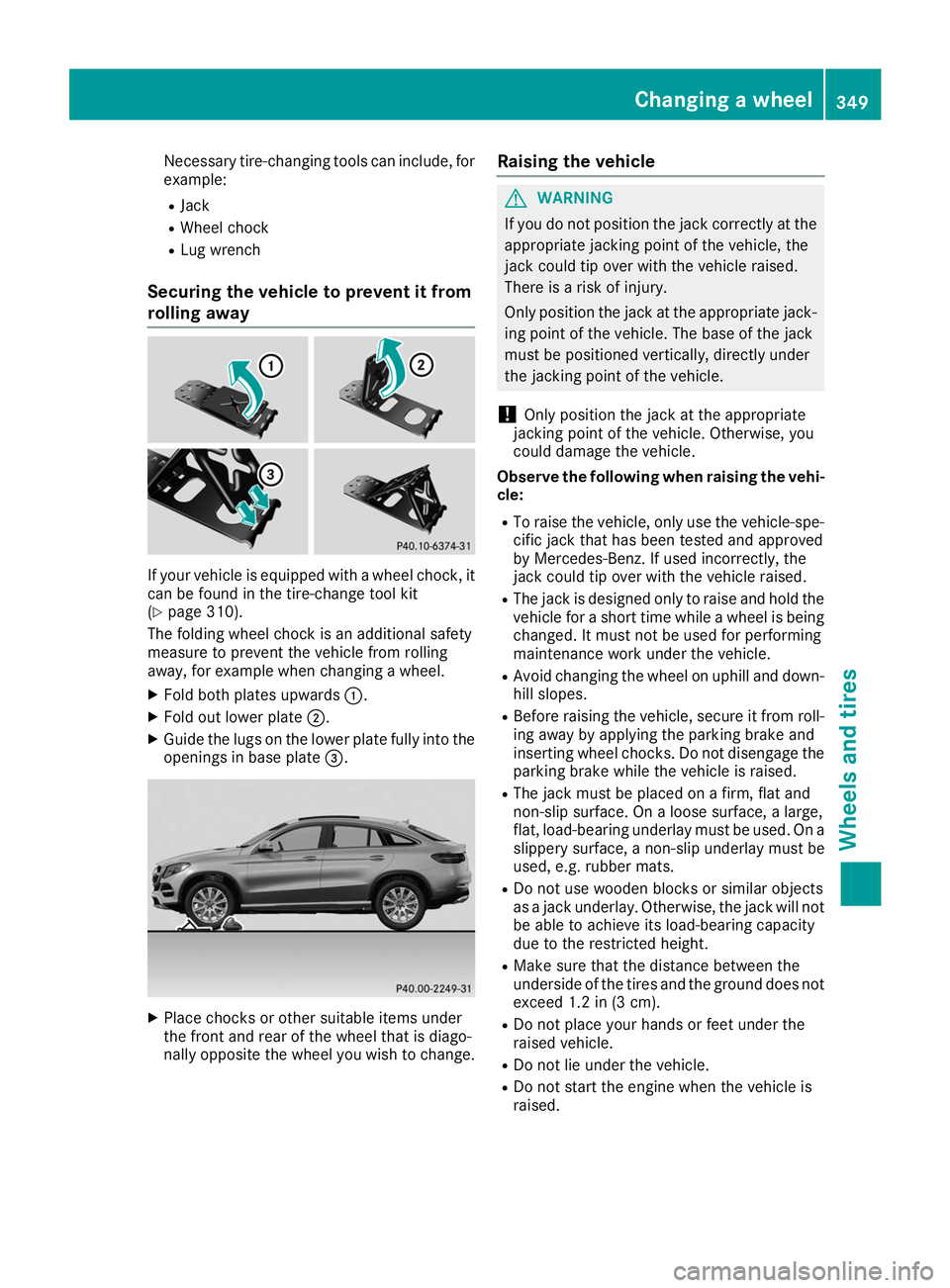
Securing the vehicle to prevent it from
rolling away If your vehicle is equipped with a wheel chock, it
can be found in the tire-change tool kit
(Y page 310).
The folding wheel chock is an additional safety
measure to prevent the vehicle from rolling
away, for example when changing a wheel.
X Fold both plates upwards 0043.
X Fold out lower plate 0044.
X Guide the lugs on the lower plate fully into the
openings in base plate 0087.X
Place chocks or other suitable items under
the front and rear of the wheel that is diago-
nally opposite the wheel you wish to change. Raising the vehicle G
WARNING
If you do not position the jack correctly at the appropriate jacking point of the vehicle, the
jack could tip over with the vehicle raised.
There is a risk of injury.
Only position the jack at the appropriate jack-
ing point of the vehicle. The base of the jack
must be positioned vertically, directly under
the jacking point of the vehicle.
! Only position the jack at the appropriate
jacking point of the vehicle. Otherwise, you
could damage the vehicle.
Observe the following when raising the vehi- cle:
R To raise the vehicle, only use the vehicle-spe-
cific jack that has been tested and approved
by Mercedes-Benz. If used incorrectly, the
jack could tip over with the vehicle raised.
R The jack is designed only to raise and hold the
vehicle for a short time while a wheel is being
changed. It must not be used for performing
maintenance work under the vehicle.
R Avoid changing the wheel on uphill and down-
hill slopes.
R Before raising the vehicle, secure it from roll-
ing away by applying the parking brake and
inserting wheel chocks. Do not disengage the parking brake while the vehicle is raised.
R The jack must be placed on a firm, flat and
non-slip surface. On a loose surface, a large,
flat, load-bearing underlay must be used. On a
slippery surface, a non-slip underlay must be
used, e.g. rubber mats.
R Do not use wooden blocks or similar objects
as a jack underlay. Otherwise, the jack will not be able to achieve its load-bearing capacity
due to the restricted height.
R Make sure that the distance between the
underside of the tires and the ground does not
exceed 1.2 in (3 cm).
R Do not place your hands or feet under the
raised vehicle.
R Do not lie under the vehicle.
R Do not start the engine when the vehicle is
raised. Changing a wheel
349Wheels and tires Z
Page 353 of 370
Mounting a new wheel
G
WARNING
Oiled or greased wheel bolts or damaged
wheel bolts/hub threads can cause the wheel bolts to come loose. As a result, you could
lose a wheel while driving. There is a risk of
accident.
Never oil or grease wheel bolts. In the event ofdamage to the threads, contact a qualified
specialist workshop immediately. Have the
damaged wheel bolts or hub threads
replaced/renewed. Do not continue driving. G
WARNING
If you tighten the wheel bolts or wheel nuts
when the vehicle is raised, the jack could tip
over. There is a risk of injury.
Only tighten the wheel bolts or wheel nuts
when the vehicle is on the ground.
! To prevent damage to the paintwork, hold
the wheel securely against the wheel hub
while screwing in the first wheel bolt.
Always pay attention to the instructions and
safety notes in the "Changing a wheel" section
(Y page 347).
Only use wheel bolts that have been designed
for the wheel and the vehicle. For safety rea-
sons, Mercedes-Benz recommends that you
only use wheel bolts which have been approved
for Mercedes-Benz vehicles and the respective
wheel.
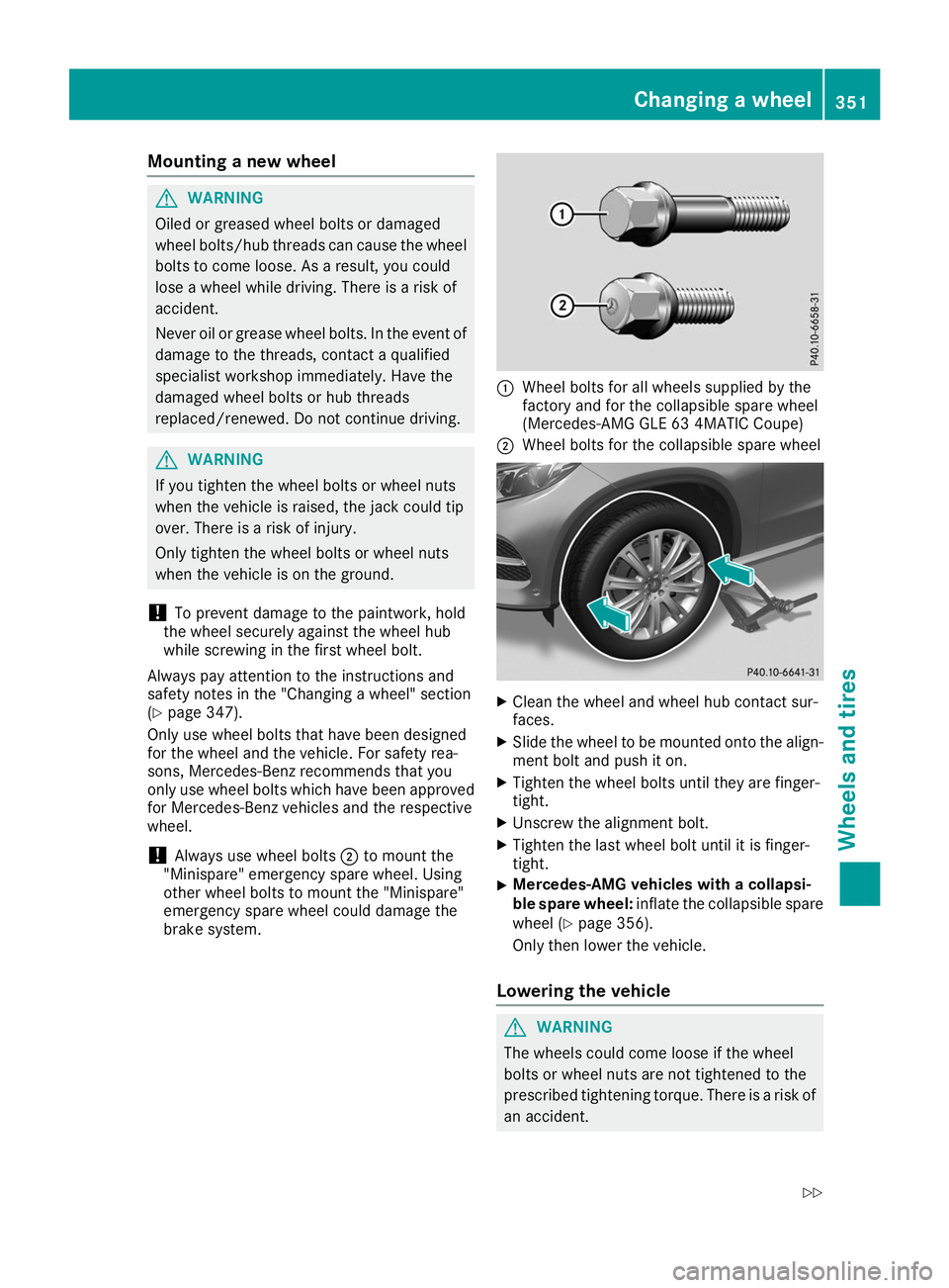
! Always use wheel bolts
0044to mount the
"Minispare" emergency spare wheel. Using
other wheel bolts to mount the "Minispare"
emergency spare wheel could damage the
brake system. 0043
Wheel bolts for all wheels supplied by the
factory and for the collapsible spare wheel
(Mercedes-AMG GLE 63 4MATIC Coupe)
0044 Wheel bolts for the collapsible spare wheel X
Clean the wheel and wheel hub contact sur-
faces.
X Slide the wheel to be mounted onto the align-
ment bolt and push it on.
X Tighten the wheel bolts until they are finger-
tight.
X Unscrew the alignment bolt.
X Tighten the last wheel bolt until it is finger-
tight.
X Mercedes-AMG vehicles with a collapsi-
ble spare wheel:
inflate the collapsible spare
wheel (Y page 356).
Only then lower the vehicle.
Lowering the vehicle G
WARNING
The wheels could come loose if the wheel
bolts or wheel nuts are not tightened to the
prescribed tightening torque. There is a risk of an accident. Changing a wheel
351Wheels and tires
Z