2019 MERCEDES-BENZ GLE COUPE oil
[x] Cancel search: oilPage 302 of 370
Further information on windshield washer fluid
(Y page 363). ASSYST PLUS
Service message
i If the scheduled service intervals are excee-
ded, this may result in damage to the vehicle.
You can obtain up-to-date information concern-
ing the servicing of your vehicle from a qualified specialist workshop, e.g. an authorized
Mercedes-Benz Center or at
http://www.mbusa.com (USA only).
i The ASSYST PLUS service interval display
does not show any information on the engine
oil level. Observe the notes on the engine oil
level (Y page 297).
The multifunction display shows a service mes-
sage for several seconds, e.g.:
R Service A in .. Days Service A in .. Days
R Service A Due
Service A Due
R Service A Exceeded by .. Days
Service A Exceeded by .. Days
Depending on the operating conditions of the
vehicle, the remaining time or distance until the next service due date is displayed.
The letter A Aor B
B, possibly in connection with a
number or another letter, shows the type of ser-
vice. A
A stands for a minor service and B
Bfor a
major service.
Further information can be obtained at a quali-
fied specialist workshop.
The ASSYST PLUS service interval display does
not take into account any periods of time during
which the battery is disconnected.
Maintaining the time-dependent service sched-
ule:
X Note down the service due date displayed in
the multifunction display before disconnect-
ing the battery.
or
X After reconnecting the battery, subtract the
battery disconnection periods from the ser-
vice date shown on the display. Hiding a service message
X Press the 0038or0076 button on the steering
wheel. Displaying service messages
X Switch on the ignition.
X Press the 0059or0065 button on the steering
wheel to select the Serv. Serv.menu.
X Press the 0063or0064 button to select the
ASSYST
ASSYST PLUS
PLUSsubmenu and confirm by press-
ing the 0076button.
The service due date appears in the multi-
function display. Information about Service
Resetting the ASSYST PLUS service
interval display !
If the ASSYST PLUS service interval display
has been inadvertently reset, this setting can
be corrected at a qualified specialist work-
shop.
Have service work carried out as described in the Maintenance Booklet. This may otherwise
lead to increased wear and damage to the
major assemblies or the vehicle.
A qualified specialist workshop will reset the
ASSYST PLUS service interval display after the
service work has been carried out. You can also obtain further information on maintenance
work, for example.
Special service requirements The specified maintenance interval takes only
the normal operation of the vehicle into
account. Under increased load on the vehicle,
maintenance work must be carried out more
frequently, for example:
R Regular city driving with frequent intermedi-
ate stops
R If the vehicle is primarily used to travel short
distances
R Use in mountainous terrain or on poor road
surfaces
R If the engine is often left idling for long periods
Under these or similar conditions, have, for
example, the air filter, engine oil and oil filter
replaced or changed more frequently. Under
arduous operating conditions, the tires must be checked more often. Further information can be
obtained at a qualified specialist workshop. 300
ASSYST PLUSMaintenance and care
Page 305 of 370
Information about the correct distance is
available from the equipment manufacturer.
Move the power washer nozzle around when
cleaning your vehicle.
The water temperature of the power washer
must not exceed 140 ‡ (60 †).
Cleaning the paintwork !
Do not affix:
R stickers
R films
R magnetic plates or similar items
to painted surfaces. You could otherwise
damage the paintwork.
Scratches, corrosive deposits, areas affected by
corrosion and damage caused by inadequate
care cannot always be completely repaired. In
such cases, visit a qualified specialist workshop.
X Remove dirt immediately, where possible,
while avoiding rubbing too hard.
X Soak insect remains with insect remover and
rinse off the treated areas afterwards.
X Soak bird droppings with water and rinse off
the treated areas afterwards.
X Remove tree resin, oils, fuels and greases by
rubbing gently with a cloth soaked in petro-
leum ether or lighter fluid
X Remove coolant and brake fluid with a moist
cloth and clear water.
X Use tar remover to remove tar stains.
X Use silicone remover to remove wax.
If water no longer forms "beads" on the paint
surface, use the paint care products recommen- ded and approved by Mercedes-Benz. This is the
case approximately every three to five months,
depending on the climate conditions and the
care product used.
If dirt has penetrated the paint surface or if the
paint has become dull, the paint cleaner recom-
mended and approved by Mercedes-Benz
should be used.
Do not use these care products in the sun or on the hood while the hood is hot.
X Use a suitable touch-up stick, e.g. MB Touch-
Up Stick, to repair slight damage to the paint- work quickly and provisionally. Matte finish care !
Never polish the vehicle or the light alloy
wheels. Polishing causes the finish to shine.
! The following can give the paint a glossy
appearance and thus reduce the matt effect:
R Rubbing hard with unsuitable agents
R Washing the vehicle in direct sunlight
! Never use paint cleaner, buffing or polishing
products, or gloss preserver, e.g. wax, for the purpose of paintwork care. These products
are only suitable for high-gloss surfaces. Their
use on vehicles with matte paintwork leads to
considerable surface damage or, more spe-
cifically, to shiny, spotted areas.
Always have paintwork repairs carried out at a
qualified specialist workshop.
! Only use automatic car washes which cor-
respond to the latest technological stand-
ards. Never use wash programs which finish
by treating the vehicle with hot wax.
Observe these notes if your vehicle has a clear
matte finish. This will help you to avoid damage
to the paintwork due to incorrect treatment.
These notes also apply to light alloy wheels with
a clear matte finish.
i Use only insect remover and car shampoo
from the range of recommended and
approved Mercedes-Benz care products.
Cleaning the decorative film !
The following may have an effect on the ser-
vice life and color of decorative film:
R sunlight
R temperature, e.g. hot-air fan
R weather conditions
R stone impacts and dirt
R chemical cleaning agents
R greasy substances
! Do not use any types of polish on matt dec-
orative film. Polishing surfaces covered with
film gives it a shiny finish.
! Do not treat matt or structured decorative
film with wax. This may lead to marks that
cannot be removed.
Observe the notes in the matte finish paintwork
care and treatment chapter (Y page 303). Care
303Maintenance and care Z
Page 308 of 370
X
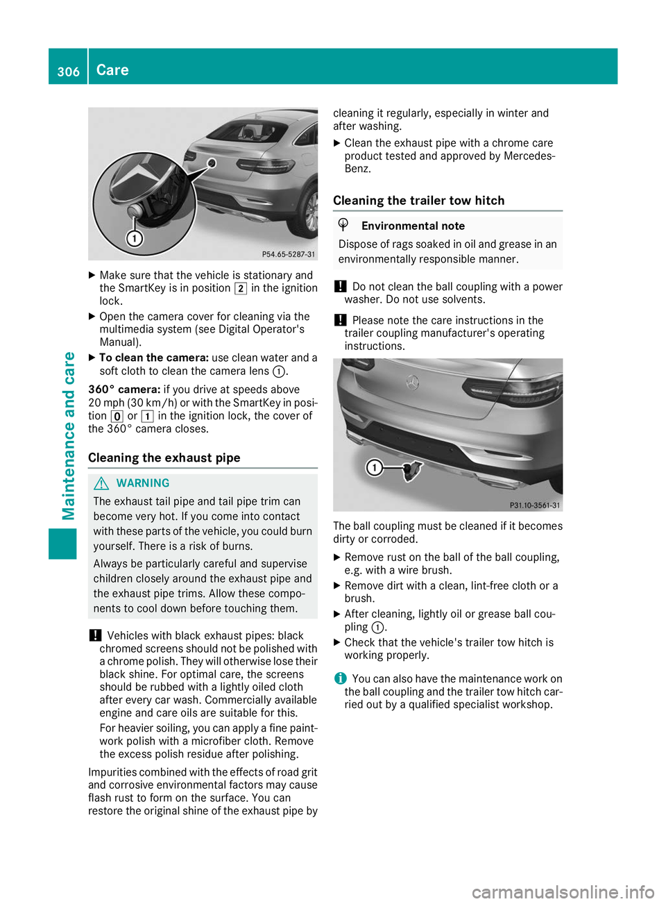
Make sure that the vehicle is stationary and
the SmartKey is in position 0048in the ignition
lock.
X Open the camera cover for cleaning via the
multimedia system (see Digital Operator's
Manual).
X To clean the camera: use clean water and a
soft cloth to clean the camera lens 0043.
360° camera: if you drive at speeds above
20 mph (30 km/h) or with the SmartKey in posi- tion 0092or0047 in the ignition lock, the cover of
the 360° camera closes.
Cleaning the exhaust pipe G
WARNING
The exhaust tail pipe and tail pipe trim can
become very hot. If you come into contact
with these parts of the vehicle, you could burn
yourself. There is a risk of burns.
Always be particularly careful and supervise
children closely around the exhaust pipe and
the exhaust pipe trims. Allow these compo-
nents to cool down before touching them.
! Vehicles with black exhaust pipes: black
chromed screens should not be polished with a chrome polish. They will otherwise lose their
black shine. For optimal care, the screens
should be rubbed with a lightly oiled cloth
after every car wash. Commercially available
engine and care oils are suitable for this.
For heavier soiling, you can apply a fine paint- work polish with a microfiber cloth. Remove
the excess polish residue after polishing.
Impurities combined with the effects of road grit
and corrosive environmental factors may cause flash rust to form on the surface. You can
restore the original shine of the exhaust pipe by cleaning it regularly, especially in winter and
after washing.
X Clean the exhaust pipe with a chrome care
product tested and approved by Mercedes-
Benz.
Cleaning the trailer tow hitch H
Environmental note
Dispose of rags soaked in oil and grease in an environmentally responsible manner.
! Do not clean the ball coupling with a power
washer. Do not use solvents.
! Please note the care instructions in the
trailer coupling manufacturer's operating
instructions. The ball coupling must be cleaned if it becomes
dirty or corroded.
X Remove rust on the ball of the ball coupling,
e.g. with a wire brush.
X Remove dirt with a clean, lint-free cloth or a
brush.
X After cleaning, lightly oil or grease ball cou-
pling 0043.
X Check that the vehicle's trailer tow hitch is
working properly.
i You can also have the maintenance work on
the ball coupling and the trailer tow hitch car-
ried out by a qualified specialist workshop. 306
CareMaintenance and care
Page 309 of 370
Interior care
Cleaning the display !
For cleaning, do not use any of the following:
R alcohol-based thinner or gasoline
R abrasive cleaning agents
R commercially-available household cleaning
agents
These may damage the display surface. Do
not put pressure on the display surface when cleaning. This could lead to irreparable dam-
age to the display.
X Before cleaning the display, make sure that it
is switched off and has cooled down.
X Clean the display surface using a commer-
cially available microfiber cloth and TFT/LCD
display cleaner.
X Dry the display surface using a dry microfiber
cloth.
Cleaning the plastic trim G
WARNING
Care products and cleaning agents containing solvents cause surfaces in the cockpit to
become porous. As a result, plastic parts may
come loose in the event of air bag deploy-
ment. There is a risk of injury.
Do not use any care products and cleaning
agents to clean the cockpit.
! Never attach the following to plastic surfa-
ces:
R stickers
R films
R perfume oil container or similar
You could otherwise damage the plastic.
! Do not allow cosmetics, insect repellent or
sunscreen to come into contact with the plas-
tic trim. This maintains the high-quality look of the surfaces.
X Wipe the plastic trim with a damp, lint-free
cloth, e.g. a microfiber cloth.
X Heavy soiling: use care and cleaning prod-
ucts recommended and approved by
Mercedes-Benz.
The surface may change color temporarily.
Wait until the surface is dry again. Cleaning the steering wheel and gear or
selector lever X
Thoroughly wipe with a damp cloth or use
leather care agents that have been recom-
mended and approved by Mercedes-Benz.
Cleaning genuine wood and trim ele-
ments !
Do not use solvent-based cleaning agents
such as tar remover, wheel cleaners, polishes
or waxes. There is otherwise a risk of damag- ing the surface.
! Do not use chrome polish on trim pieces.
The trim pieces have a chrome look but are
mostly made of anodized aluminum and can
lose their shine if chrome polish is used. Use
a damp, lint-free cloth instead when cleaning the trim pieces.
If the chrome-plated trim pieces are very
dirty, you can use a chrome polish. If you are
unsure as to whether the trim pieces are
chrome-plated or not, consult an authorized
Mercedes-Benz Center.
X Wipe the wooden trim and trim pieces with a
damp, lint-free cloth, e.g. a microfiber cloth.
X Heavy soiling: use car care and cleaning
products recommended and approved by
Mercedes-Benz.
Cleaning the seat covers General notes
! Do not use a microfiber cloth to clean covers
made out of real leather, artificial leather or
DINAMICA. If used often, these can damage
the cover.
i Note that regular care is essential to ensure
that the appearance and comfort of the cov-
ers is retained over time. Care
307Maintenance and care Z
Page 311 of 370
Where will I find...?
Reflective safety jacket
Removing/replacing the reflective
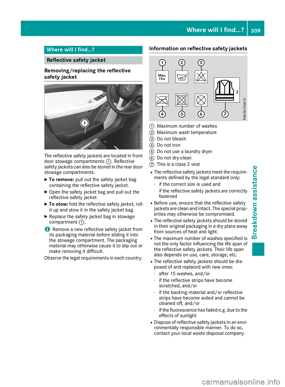
safety jacket The reflective safety jackets are located in front
door stowage compartments 0043. Reflective
safety jackets can also be stored in the rear door stowage compartments.
X To remove: pull out the safety jacket bag
containing the reflective safety jacket.
X Open the safety jacket bag and pull out the
reflective safety jacket.
X To stow: fold the reflective safety jacket, roll
it up and stow it in the safety jacket bag.
X Replace the safety jacket bag in stowage
compartment 0043.
i Remove a new reflective safety jacket from
its packaging material before sliding it into
the stowage compartment. The packaging
material may otherwise cause it to slip out or
make removing it difficult.
Observe the legal requirements in each country. Information on reflective safety jackets 0043
Maximum number of washes
0044 Maximum wash temperature
0087 Do not bleach
0085 Do not iron
0083 Do not use a laundry dryer
0084 Do not dry-clean
006B This is a class 2 vest
R The reflective safety jackets meet the require-
ments defined by the legal standard only:
- if the correct size is used and
- if the reflective safety jackets are correctly
fastened
R Before use, ensure that the reflective safety
jackets are clean and intact. The special prop-
erties may otherwise be compromised.
R The reflective safety jackets should be stored
in their original packaging in a dry place away
from sources of heat and light.
R The maximum number of washes specified is
not the only factor influencing the life span of
the reflective safety jackets. Their life span
also depends on use, care, storage, etc.
R The reflective safety jackets should be dis-
posed of and replaced with new ones:
- after 15 washes, and/or
- if the reflective strips have become
scratched, and/or
- if the backing material and/or reflective
strips have become soiled and cannot be
cleaned off, and/or
- if the fluorescence has faded e.g. due to the
effects of sunlight
R Dispose of reflective safety jackets in an envi-
ronmentally responsible manner. To do so,
contact your local waste disposal company. Where will I find...?
309Breakdown assistance
Page 315 of 370
X
Do not remove any foreign objects which have
penetrated the tire, e.g. screws or nails.
X Remove the tire sealant bottle, the accompa-
nying TIREFIT sticker and the tire inflation
compressor from the stowage well under-
neath the cargo compartment floor
(Y page 310).
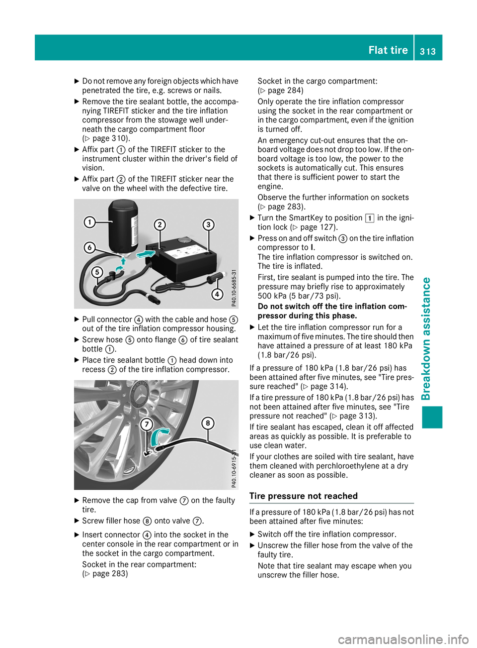
X Affix part 0043of the TIREFIT sticker to the
instrument cluster within the driver's field of
vision.
X Affix part 0044of the TIREFIT sticker near the
valve on the wheel with the defective tire. X
Pull connector 0085with the cable and hose 0083
out of the tire inflation compressor housing.
X Screw hose 0083onto flange 0084of tire sealant
bottle 0043.
X Place tire sealant bottle 0043head down into
recess 0044of the tire inflation compressor. X
Remove the cap from valve 006Bon the faulty
tire.
X Screw filler hose 006Conto valve 006B.
X Insert connector 0085into the socket in the
center console in the rear compartment or in
the socket in the cargo compartment.
Socket in the rear compartment:
(Y page 283) Socket in the cargo compartment:
(Y page 284)
Only operate the tire inflation compressor
using the socket in the rear compartment or
in the cargo compartment, even if the ignition
is turned off.
An emergency cut-out ensures that the on-
board voltage does not drop too low. If the on-
board voltage is too low, the power to the
sockets is automatically cut. This ensures
that there is sufficient power to start the
engine.
Observe the further information on sockets
(Y page 283).
X Turn the SmartKey to position 0047in the igni-
tion lock (Y page 127).
X Press on and off switch 0087on the tire inflation
compressor to I.
The tire inflation compressor is switched on.
The tire is inflated.
First, tire sealant is pumped into the tire. The
pressure may briefly rise to approximately
500 kPa (5 bar/73 psi).
Do not switch off the tire inflation com-
pressor during this phase.
X Let the tire inflation compressor run for a
maximum of five minutes. The tire should then have attained a pressure of at least 180 kPa
(1.8 bar/26 psi).
If a pressure of 180 kPa (1.8 ba r/26 psi) has
been at tained after five minutes, see "Tire pres-
sure reached" (Y page 314).
If a tire pressure of 180 kPa (1.8 bar/26 psi) has not been attained after five minutes, see "Tire
pressure not reached" (Y page 313).
If tire sealant has escaped, clean it off affected
areas as quickly as possible. It is preferable to
use clean water.
If your clothes are soiled with tire sealant, have them cleaned with perchloroethylene at a dry
cleaner as soon as possible.
Tire pressure not reached If a pressure of 180 kPa (1.8 bar/26 psi) has not
been attained after five minutes:
X Switch off the tire inflation compressor.
X Unscrew the filler hose from the valve of the
faulty tire.
Note that tire sealant may escape when you
unscrew the filler hose. Flat tire
313Breakdown assistance Z
Page 348 of 370
Recommended tire pressures
The recommended tire pressure applies to the
tires mounted at the factory.
The Tire and Loading Information placard con-
tains the recommended tire pressures for cold
tires on a fully loaded vehicle and for the maxi-
mum permissible vehicle speed.
The tire pressure table contains the recommen- ded pressures for cold tires for various operat-
ing conditions, i.e. differing load and speed con- ditions.
Increased vehicle weight due to optional
equipment
The combined weight of all standard and
optional equipment available for the vehicle,
regardless of whether it is actually installed on
the vehicle or not.
Rim This is the part of the wheel on which the tire is
mounted.
GAWR (Gross Axle Weight Rating)
The GAWR is the maximum gross axle weight
rating. The actual load on an axle must never
exceed the gross axle weight rating. The gross
axle weight rating can be found on the vehicle
identification plate on the B-pillar on the driver's side.
Speed rating
The speed rating is part of the tire identification. It specifies the speed range for which the tire isapproved.
GTW (Gross Trailer Weight)
The GTW is the weight of a trailer including the
weight of the load, luggage, accessories etc. on the trailer.
GVW (Gross Vehicle Weight) The gross vehicle weight includes the weight of
the vehicle including fuel, tools, the spare wheel, accessories installed, occupants, luggage and
the drawbar noseweight, if applicable. The gross vehicle weight must not exceed the gross vehi-
cle weight rating GVWR as specified on the vehi-
cle identification plate on the B-pillar on the
driver's side. GVWR (Gross Vehicle Weight Rating)
The GVWR is the maximum permissible gross
weight of a fully loaded vehicle (the weight of the
vehicle including all accessories, occupants,
fuel, luggage and the drawbar noseweight, if
applicable). The gross vehicle weight rating is
specified on the vehicle identification plate on
the B-pillar on the driver's side.
Maximum loaded vehicle weight
The maximum weight is the sum of:
R the curb weight of the vehicle
R the weight of the accessories
R the load limit
R the weight of the factory installed optional
equipment
Kilopascal (kPa) Metric unit for tire pressure. 6.9 kPa corre-
sponds to 1 psi. Another unit for tire pressure is
bar. 100 kilopascals (kPa) are the equivalent of
1 bar.
Load index
In addition to the load-bearing index, the load
index may also be imprinted on the sidewall of
the tire. This specifies the load-bearing capacity more precisely.
Curb weight
The weight of a vehicle with standard equipment
including the maximum capacity of fuel, oil and
coolant. It also includes the air-conditioning sys- tem and optional equipment if these are instal-
led in the vehicle, but does not include passen-
gers or luggage.
Maximum load rating
The maximum tire load is the maximum permis- sible weight in kilograms or lbs for which a tire is
approved.
Maximum permissible tire pressure
Maximum permissible tire pressure for one tire.
Maximum load on one tire
Maximum load on one tire. This is calculated by
dividing the maximum axle load of one axle by
two. 346
All about wheels and tiresWheels and tires
Page 350 of 370
ponents may also be damaged. There is a risk
of an accident.
Rotate front and rear wheels only if the wheels
and tires are of the same dimensions.
! On vehicles equipped with a tire pressure
monitor, electronic components are located
in the wheel.
Tire-mounting tools should not be used near
the valve. This could damage the electronic
components.
Only have tires changed at a qualified spe-
cialist workshop.
Always observe the instructions and safety
notes in the "Mounting a wheel" section
(Y page 348).
The wear patterns on the front and rear tires
differ, depending on the operating conditions.
Rotate the wheels before a clear wear pattern
has formed on the tires. Front tires typically
wear more on the shoulders and the rear tires in
the center.
On vehicles that have the same size front and
rear wheels, you can rotate the wheels accord-
ing to the intervals in the tire manufacturer's
warranty book in your vehicle documents. If no
warranty book is available, the tires should be
rotated every 3,000 to 6,000 miles (5,000 to
10,000 km). Depending on tire wear, this may
be required earlier. Do not change the direction
of wheel rotation.
Clean the contact surfaces of the wheel and the brake disc thoroughly every time a wheel is rota-
ted. Check the tire pressure and, if necessary,
restart the tire pressure loss warning system or
the tire pressure monitor (Y page 334).Direction of rotation
Tires with a specified direction of rotation have
additional benefits, e.g. if there is a risk of hydro-
planing. These advantages can only be gained if the tires are installed corresponding to the
direction of rotation.
An arrow on the sidewall of the tire indicates its
correct direction of rotation. Storing wheels
Store wheels that are not being used in a cool,
dry and preferably dark place. Protect the tires
from oil, grease, gasoline and diesel. Mounting a wheel
Preparing the vehicle X
Vehicle with emergency spare wheel:
when mounting the emergency spare wheel in
the event of a flat tire, follow the additional
notes on vehicle preparation under "Flat tire" (Y page 310).
X Stop the vehicle on solid, non-slippery and
level ground.
X Apply the electric parking brake manually.
X Bring the front wheels into the straight-ahead
position.
X Vehicles with automatic transmission:
shift the transmission to position
005D.
X Vehicles with the AIRMATIC package:
make sure that the normal vehicle level is
selected (Y page 170).
X Switch off the engine.
X Vehicles without KEYLESS-GO: remove the
SmartKey from the ignition lock.
X Vehicles with KEYLESS-GO: open the driv-
er's door.
The vehicle electronics are now in position
0092. This means no SmartKey is in the ignition lock.
X Vehicles with KEYLESS-GO: remove the
Start/Stop button from the ignition lock
(Y page 127).
X Make sure that the engine cannot be started
via your smartphone (Y page 129).
X If included in the vehicle equipment, remove
the tire-change tool kit from the vehicle.
X Safeguard the vehicle against rolling away.
i Apart from certain country-specific varia-
tions, vehicles are not equipped with a tire-
change tool kit. For more information on
which tools are required to perform a wheel
change on your vehicle, consult a qualified
specialist workshop. 348
Changing a wheelWheels and tires